

Page 1

TROLL Link 101 and 201 Setup
The TROLL Link 101 and 201 systems connect to the InSitu Data Center, and arrive pre-configured to your
settings. Access the Data Center to view your site.
To change settings or learn more about the Data Center,
see the In-Situ Data Center section.
You must change Win-Situ Software
communication settings to match the device
address next time you connect the
instrument.
Field Installation
3. Connect the up-hole end of the cable to the bulkhead
connector of the enclosure.
4. Install the instrument in its deployment location. Refer to
the instrument Operator's Manual for any questions
regarding proper connection or deployment.
5. Ensure the cable does not apply excessive weight on the
enclosure by securing the cable grip.
Trim the solar panel wire before inserting it
into an enclosure.
Do not cut through the entire solar panel wire.
The blade creates a current loop when in
contact with both leads and shorts the solar
panel.
Changing the Device Address
When networking multiple Level TROLL, Aqua TROLL,
Rugged TROLL, or RDO PRO Instruments, each device
requires a unique device address.
Complete the following steps with the instrument
connected to the software.
1. Click the Device Setup tab.
2. Click the Modbus Setup... button.
3. Select the Device Address box and change the
number to the desired value, making sure to not
duplicate an address within the network.
4. Click the check mark to save changes. Click Yes when
asked to proceed.
5. Click No when prompted to save the changes as the
new default settings.
Connecting the Antenna - TROLL Link 101 Only
1. Screw the antenna and gasket onto the antenna
connector, located on the top of the enclosure mounting
bracket.
Connecting and Deploying Instruments
Ensure data-logging capable instruments have been
programmed with a data log before completing the
following steps. Refer to the instrument manual for
instructions on programming a data log. Ensure alarm
conditions have been programmed (if applicable).
Ensure all instruments have been properly, uniquely
addressed in Win-Situ Software with the correct Modbus
settings.
Perform the following steps for each instrument.
Ensure you are installing the instrument in its
proper location.
1. Connect the instrument to the RuggedCable using the
twist-lock connector. The twist-lock connector clicks
when the connection is tight.
2. Remove the red dust cap from the bulkhead connector
of the enclosure.
Installing the TROLL Link Telemetry System
To mount the enclosure, you may obtain a mounting tripod
or install your own pole. Install the pole before proceeding.
1. Hold the enclosure to the pole at the desired height (be
sure to leave room at the top of the pole for the solar
panel).
2. Place a hose clamp or U-bolt into the two cutouts of the
top bracket of the enclosure and around the pole.
3. For
4. Remove the two yellow caps from the vent tube inside
hose clamps tighten the clamp until the enclosure
does not move. Attach the second hose clamp to the
bottom of the enclosure.
U-bolts Place the smaller bracket over the open
For
ends of the bolt. Use split-lock washers and nuts to
tighten the assembly to the pole.
Repeat for any remaining open brackets.
the enclosure. Attach the desiccant tube to the vent
tube.
Installing a 1 W Solar Panel
A solar panel must be installed with the communication
system. It can be installed on the same pole.
1. Hold the solar panel near the top of the pole. Point the
panel towards the equator. Adjust the panel angle for
optimum sunlight reception.
2. Thread the U-bolt through the solar panel bracket. Place
the smaller bracket over the open ends of the bolt. Use
the split-lock washers and nuts to tighten the assembly
to the pole. Repeat for any remaining open brackets.
Instead, trim off the insulation, then cut one
wire at a time.
Connect a solar panel.
1. Cover the solar panel so it will not receive any sunlight.
2. Remove one of the dome connector caps on the outside
of the enclosure.Remove the port plug. Save the plug
for later use (you can store the plug inside the
enclosure).
3. Insert the solar panel cable into the dome connector cap,
and then through the enclosure.
4. Strip the cable ends to 1.3 cm (0.5 inches).
5. Connect the black lead (negative) from the solar panel to
open screw terminal SOL-. Tighten the screw terminal.
6. Connect the white lead (positive) from the solar panel to
open screw terminal SOL+. Tighten the screw terminal.
7. Tighten the dome connector cap so the port with the
cable will be watertight.
0058332 | Rev. 000* | 12/2012
Page 2
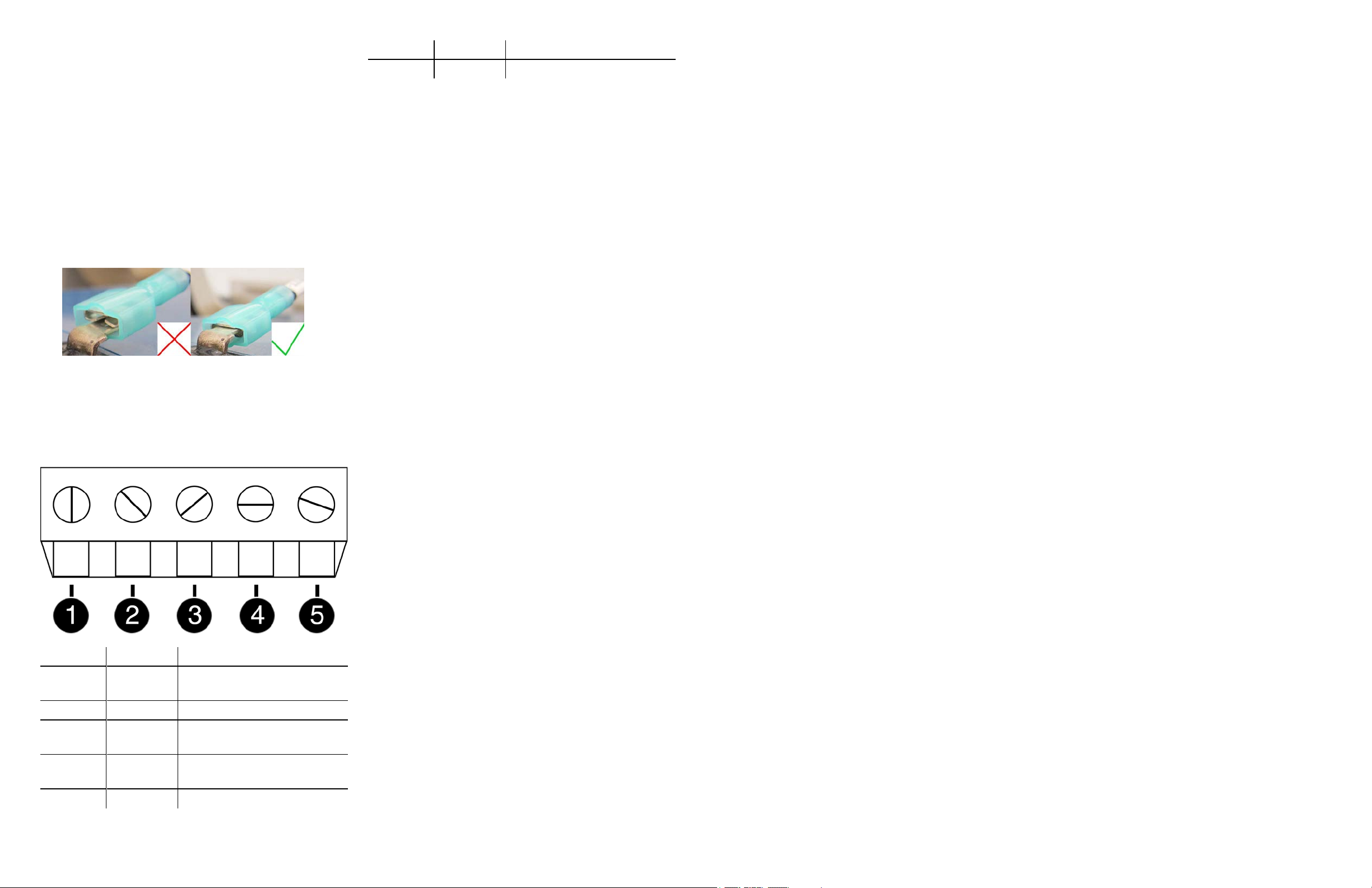
Installing a 10 or 20 W Solar Panel and External
Battery Kit
Please refer to the TROLL Link Manual for instructions on
installing a 10 or 20 W Solar Panel and External Battery
Kit.
Installing a Battery
1. Install batteries with the terminals oriented toward the
top of the enclosure.
2. Plug the black (negative) leads into the black terminals of
the batteries first. Ensure that the terminal does not sit
between the lead clip and the plastic sheath, but that the
lead clip encompasses the battery terminal.
Number Function Wire
wire
Accessing the Data Center
Note that it may take up to an hour for data to be
transmitted to the Data Center, depending on the data
service package you have.
1. Open a Web browser.
2. Enter the URL:
http://www.isi-data.com
3. Enter your User ID and Password supplied by In-Situ.
Click Login.
Enclosure Desiccant
It is extremely important to use a properly-sized
desiccant for your deployment, and to change desiccant
before the entire volume has turned pink. Use
enough desiccant to effectively keep electronics dry until
your next scheduled maintenance. Desiccant life span is
dependent on site conditions.
The enclosure contains one tube of desiccant that absorbs
moisture as it enters the enclosure through the vent tube.
Keep the vent tube clear of obstructions. Replace as
needed. An additional desiccant pack may be located at
the top of the enclosure. Replace or dry as needed.
Cleaning
3. Plug the red (positive) leads into the red battery
terminals. Ensure that the terminal does not sit between
the lead clip and the plastic sheath, but that the lead clip
encompasses the battery terminal.
TROLL Link 101 and 201 Wiring Diagram
4. The Site Index appears. The Site Index displays the site
name, most recent message received date, number of
devices at the site, and the alarm status.
5. Click a site name to view more data from that site.
6. Select a Device to view more data from that device.
If the next transmission interval has not occurred,
you should confirm that communication from all
devices in the network has been successful.
1. Ensure all components of the TROLL Link Telemetry
System have power applied.
2. From the Site Index, click the site name.
3. Click the first device listed.
4. Select Manage Device under the Site Management
heading in the left navigation bar.
5. Select View Config Messages under the Device
Config heading in the left navigation bar.
If data does not refresh at the expected rate or the site
does not display the network, contact technical support.
Clean the outside of the enclosure with a soft, damp cloth.
Do not use ammonia or other harsh chemicals.
Maintenance
Number Function Wire
1
2 RS485 (-) Bulkhead green wire
3
4
5 DC (+)
Inf ormation s ubjec t to change without notice. In-S itu, I n-S itu logo, BaroMerge, BaroTROLL, HERMIT, iS itu, Poc ket -S it u, RDO, R uggedCable, RuggedReader, T RO LL, and Win-Situ are trademark s or regist ered t rademarks of I n-Situ Inc .©2013. A ll right s reserv ed.
DC Com
(-)
RS485
ground
RS485
(+)
Bulkhead black wire; solar
panel black wire
Bulkhead blue wire
Bulkhead red wire; fuse blue
Fuse Replacement
Two fuses are located on the left edge inside of the
enclosure. The left fuse connects to the internal battery,
the right fuse connects to the charger/external power. The
fuses are 2 amp, time-delay, speed-type fuses rated for
250 VAC. Replace as needed.
 Loading...