

Page 1
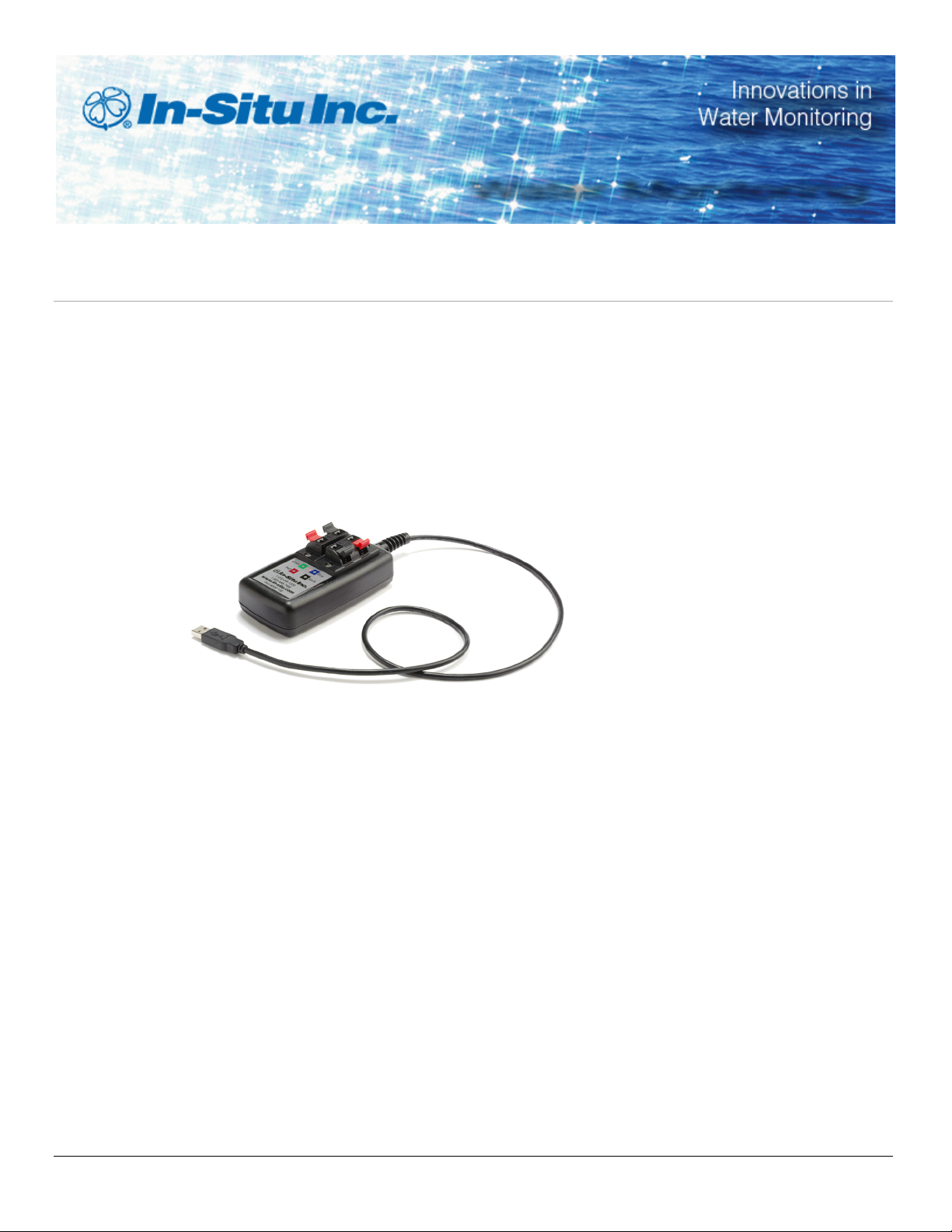
Communication Device Kit
Part number 0081100
Kit Contents
l Communication device
l Software CD
l 9 V battery
l You can also purchase a calibration kit for the instrument, which includes a
calibration chamber and a bottle of sodium sulfite solution.
Instruction Sheet
Install and Open the Software
1. Place the CD in your computer and double-click Run ShelExec.exe.
2. Select the Comm Kit Software link. Follow the prompts to install the software.
3. Ensure that you select the option to install USB drivers.
4. Double-click the Comm Kit Software desktop icon, or open the software from
Start/All Programs/In-Situ Inc.
Connect the Instrument to a Computer
The Communication Device connects a stripped-and-tinned RDO PRO-X Probe, RDO
Titan, or Aqua TROLL 400 Instrument to a computer via USB connection.
1. The communication device includes an electrical connection diagram label. To
attach the sensor to the Communication Device, depress a lever and insert the
Informationsubject to changewithout notice. In-Situ, In-Situ logo, BaroMerge, BaroTROLL, HERMIT, iSitu, Pocket-Situ, RDO,
RuggedCable, RuggedReader, TROLL, and Win-Situ are trademarks or registered trademarks of In-Situ Inc.©2013. All rights reserved.
0081102 | Rev. 003 | 11/2013
Page 2
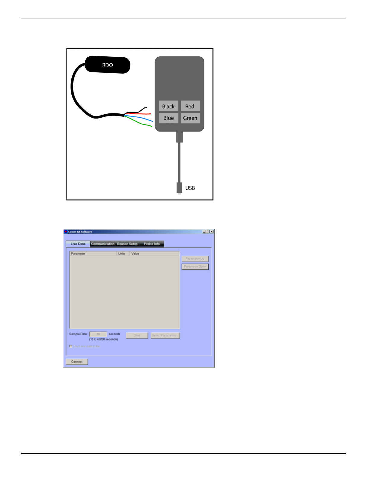
appropriate wire in the location specified by the diagram.
2. Attach the USB connector to a USB port on the computer.
3. Wait a minute for the computer to recognize the USB device then click the Connect
button.
4. If the software does not connect to the software, you can find the COM port that your
computer has assigned in Windows®Device Manager/Ports.
800-446-7488 2 www.in-situ.com
Page 3
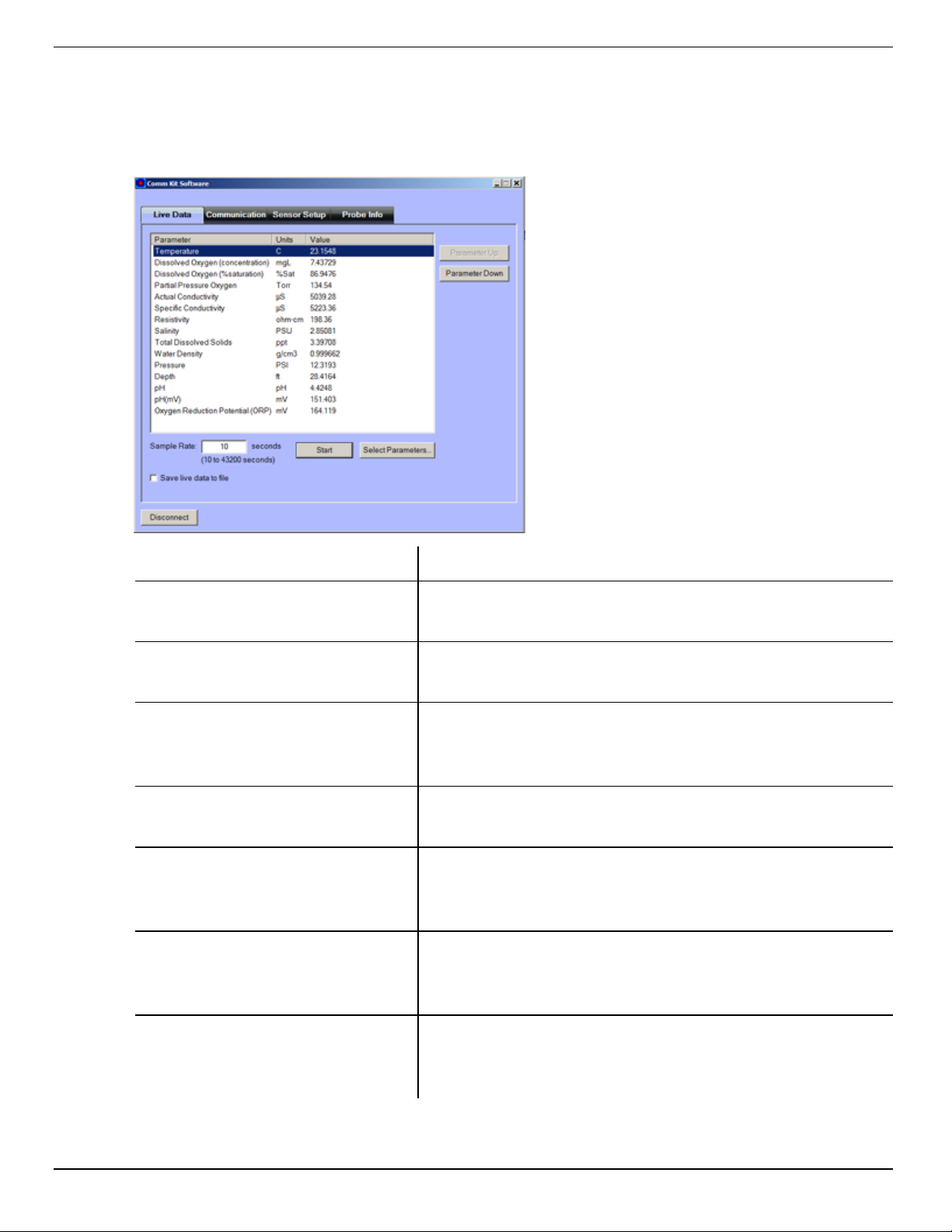
View Live Readings
When the instrument is connected to the software, a snap shot of data appears on
screen. If you want live readings to continue, click the Start button.
Screen Element Purpose
Connect/Disconnect
(button)
Sample Rate
(text field)
Save live data to file
(checkbox)
Start/Stop
(button)
Select Parameters
(button)
Parameter Up
(button)
Establishes connection and disconnection between the
instrument and the software.
Allows you to enter the rate at which the instrument will
report measurements.
Saves data to a .csv file on your computer. Once the
checkbox is selected, click Start to begin saving data to
a location of your choice on your computer.
Starts and stops data polling.
Allows you to enable and disable parameters. Click the
Select Parameters button and click the checkboxes to
select or clear parameters.
Allows you to move a parameter higher in the list. Click
the parameter and then click the Parameter Up button
until the desired location is reached.
Parameter Down
(button)
800-446-7488 3 www.in-situ.com
Allows you to move a parameter lower in the list. Click
the parameter and then click the Parameter Down
button until the desired location is reached.
Page 4
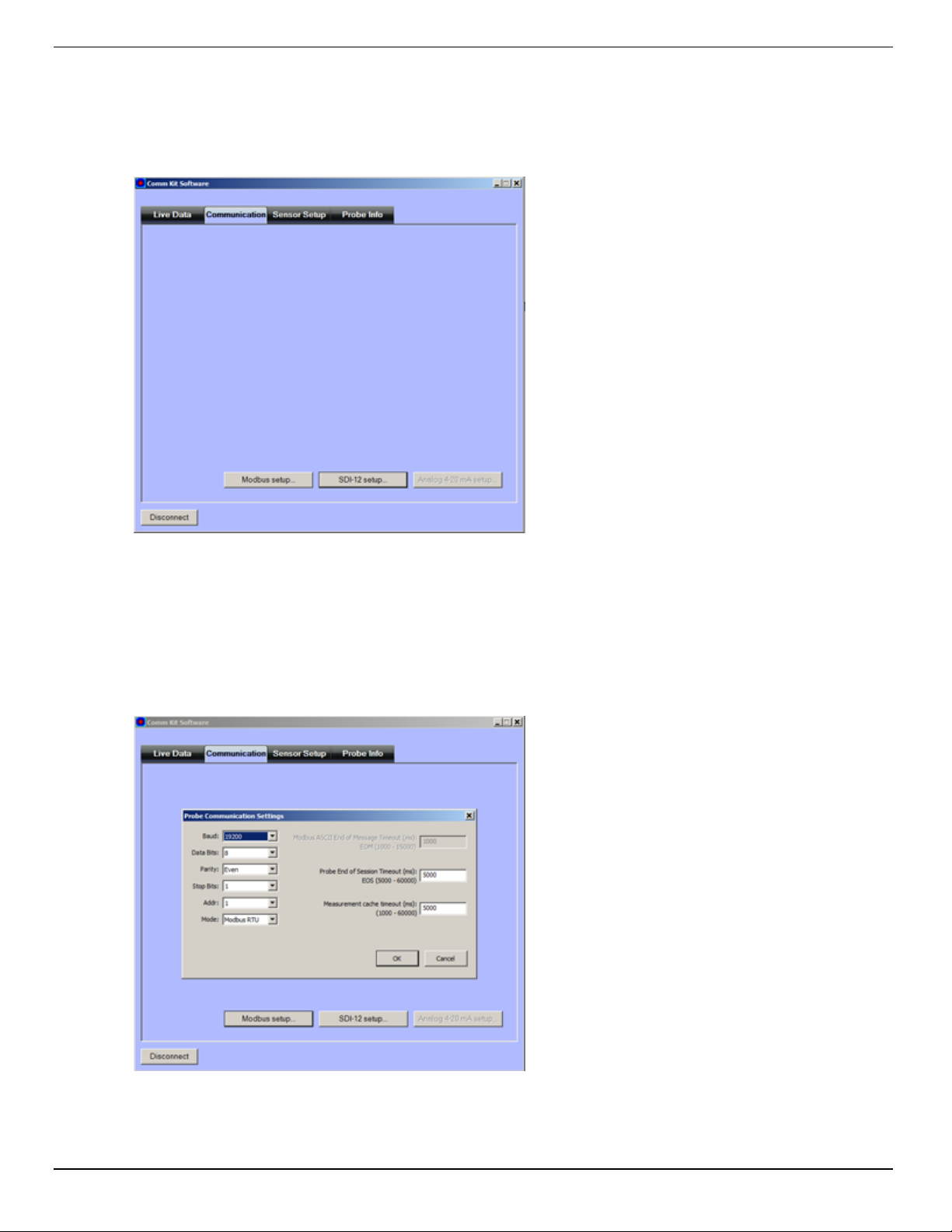
Adjust Communications Outputs
The Communication Tab allows you to configure your instrument to communicate via
Modbus or SDI-12 protocols. The instrument can use only one of the protocols at a time.
Modbus Setup
Click the Modbus setup button and assign instrument settings according to the
requirements of your controller. For instrument Modbus registers, see the Aqua
TROLL®400 Modbus and SDI-12 Reference Guide.
800-446-7488 4 www.in-situ.com
Page 5
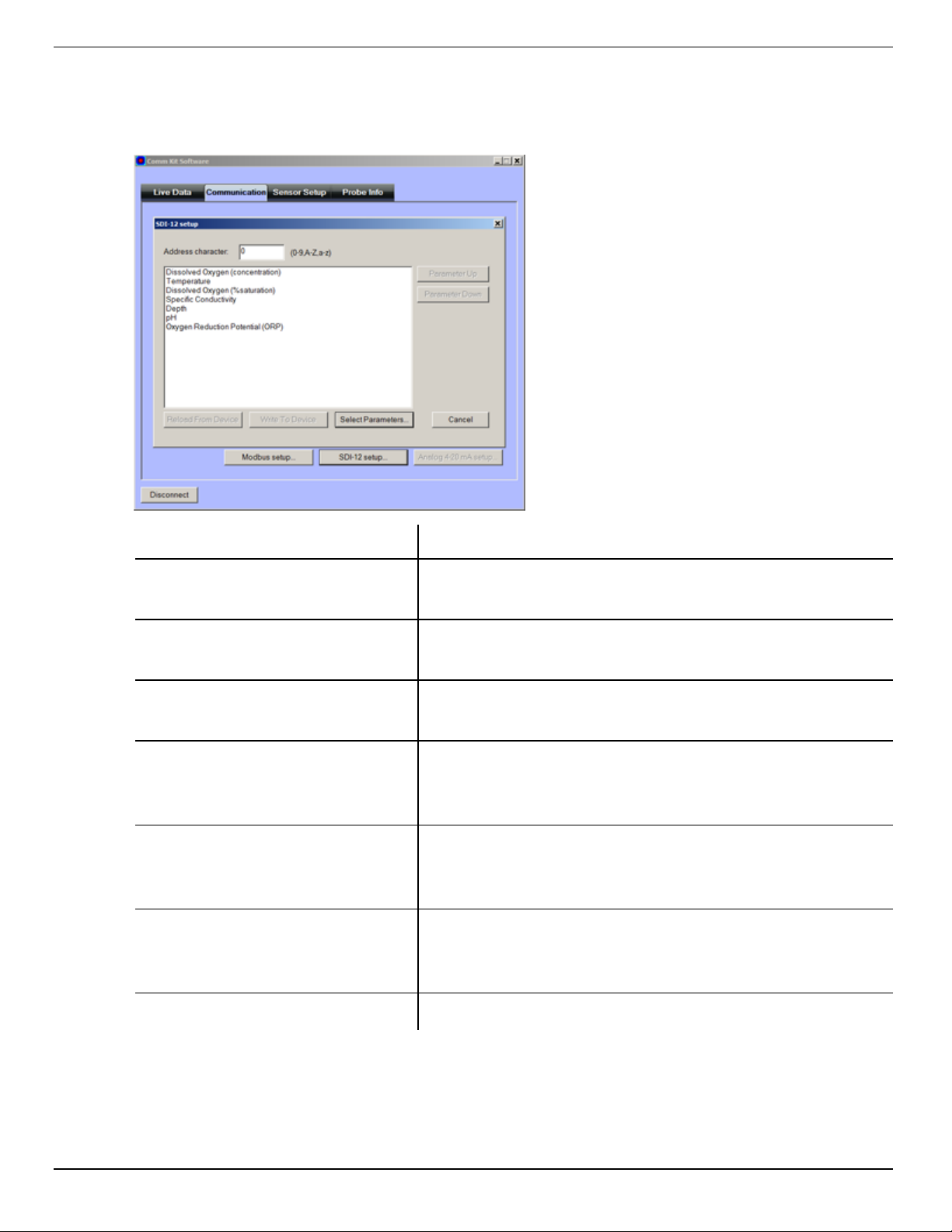
SDI-12 Setup
SDI-12 setup allows you to set the instrument address, select the parameters you
intend to log, and select the order in which the parameters will appear in the log file.
Screen Element Purpose
Address character
(text field)
Reload from Device
(button)
Write to Device
(button)
Select Parameters
(button)
Parameter Up
(button)
Parameter Down
(button)
Allows you to assign a unique SDI-12 address to the
instrument. Use 0-9, A-Z, or a-z.
Restores the settings that were last written to the
instrument.
Writes the parameters and the address to the
instrument.
Allows you to enable and disable parameters. Click the
Select Parameters button and click the checkboxes to
select or clear parameters.
Allows you to move a parameter higher in the list. Click
the parameter and then click the Parameter Up button
until the desired location is reached.
Allows you to move a parameter lower in the list. Click
the parameter and then click the Parameter Down
button until the desired location is reached.
Cancel Returns you to the Communications tab without saving.
800-446-7488 5 www.in-situ.com
Page 6
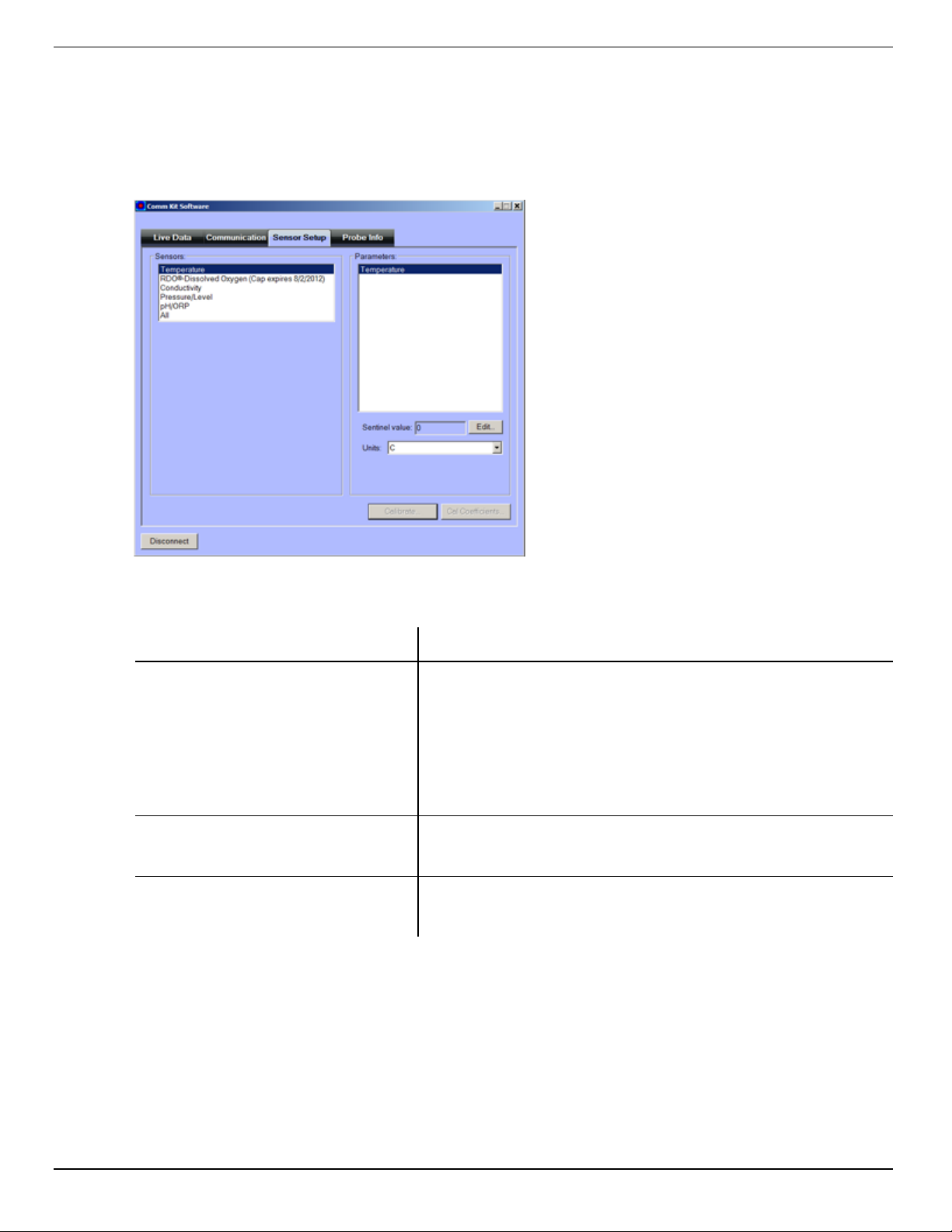
Sensor Setup Tab
The Sensor Setup Tab allows you to configure and calibrate sensors, assign the
sentinel value, and set units for parameters. When a sensor is selected, configuration
options specific to that sensor appear on screen.
Temperature Sensor
Screen Element Purpose
Sentinel value
(text field)
Edit
(button)
Units
(list)
Displays the current sentinel value. The sentinel value
is the number that will display when there is a
communication problem with the sensor. It is important
to set the sentinel value to a number that would be an
unlikely reading for the parameter under regular
operating conditions.
Allows you to edit the sentinel value for the selected
parameter.
Allows you to assign the unit for the selected
parameter.
800-446-7488 6 www.in-situ.com
Page 7
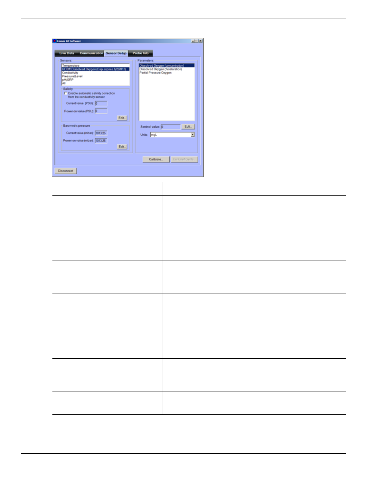
RDO Sensor
Screen Element Purpose
Enable automatic salinity
correction from the conductivity
sensor (checkbox)
Current value (PSU) (text field)
Default (PSU)
text field
Edit
(button)
Current value (mbar) (text field)
Default (baro)
Select the checkbox to use the reading from the
integrated conductivity sensor. Clear the checkbox if
you want to enter a fixed PSU value, and then click
Edit.
Displays the value that is currently used for salinity
correction.
Displays the value that will be used for salinity
correction by default when you apply power to the
instrument.
Allows you to change the Default (PSU) text field.
Displays the value that is currently used for barometric
pressure correction. Note: If your controller reads
barometric pressure, it can be read into the current
value.
Displays the value that will be used for barometric
correction by default when you apply power to the
instrument.
Edit
(button)
800-446-7488 7 www.in-situ.com
Allows you to change the Default (mbar) text field.
Page 8
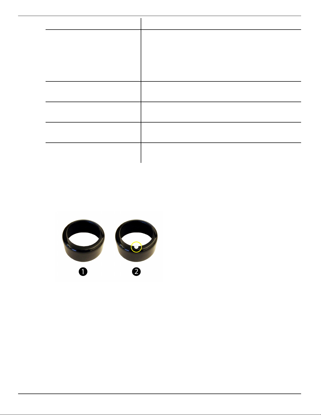
Screen Element Purpose
Displays the current sentinel value. The sentinel value
is the number that will display when there is a
Sentinel value
(text field)
communication problem with the sensor. It is important
to set the sentinel value to a number that would be an
unlikely reading for the sensor under regular operating
conditions.
Edit
(button)
Units
(list)
Calibrate
(button)
Cal Coefficients (button)
RDO Sensor Calibration
Calibrate 100% Oxygen Saturation
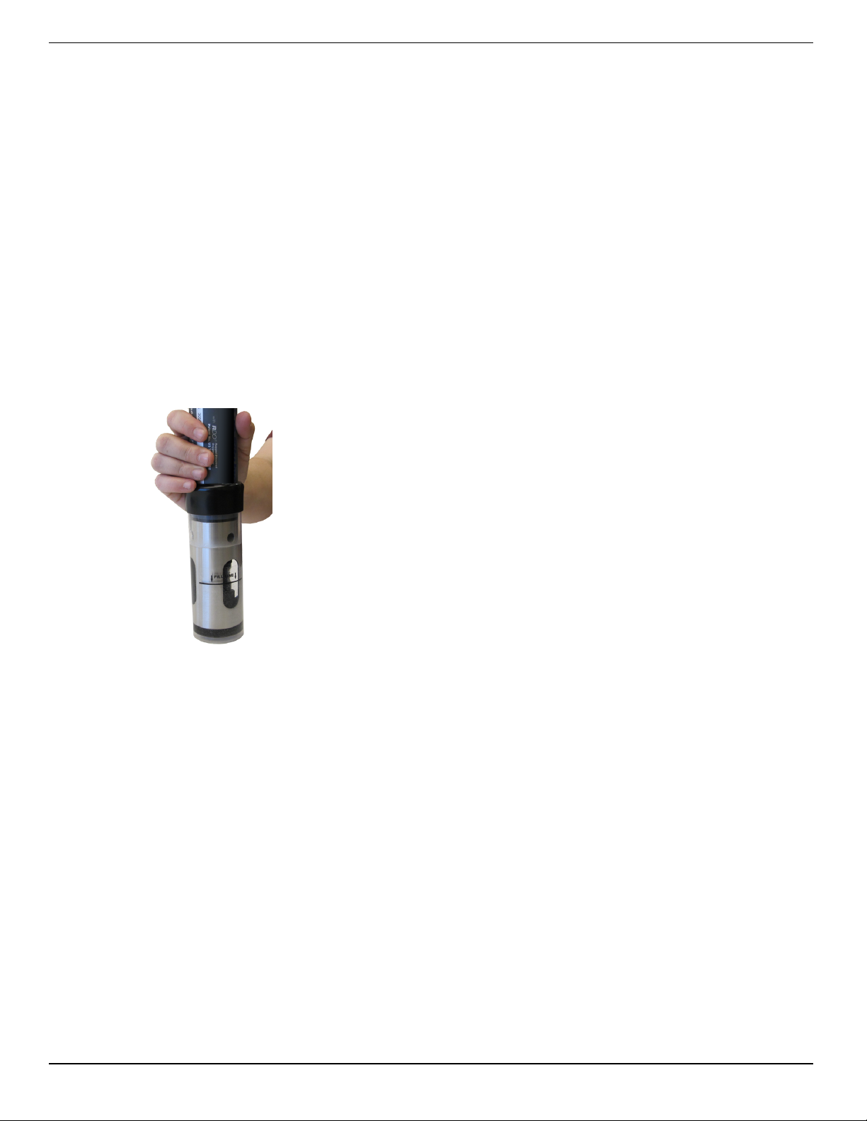
1. Place the calibration cap, with the vent hole, on the top of the calibration chamber.
Allows you to edit the sentinel value for the selected
parameter.
Allows you to assign the unit for the selected
parameter.
Starts the Calibration Wizard.
Allows you to view the most recent calibration
coefficients stored on the instrument.
2. Place the sponge wafer in the bottom of the calibration cup and saturate the sponge
wafer with approximately 10 mL clean water.
3. Gently dry the probe and sensing material with a paper towel. Ensure that the probe
and the sensing surface are free of water and fouling.
4. Place the instrument into the calibration chamber.
800-446-7488 8 www.in-situ.com
Page 9
5. Wait 5 to 10 minutes for temperature stabilization prior to calibration.
Note: Do not leave the instrument in the calibration cup for more
than 30 minutes. This can cause condensation to form on the
sensing material, providing false low readings after calibration.
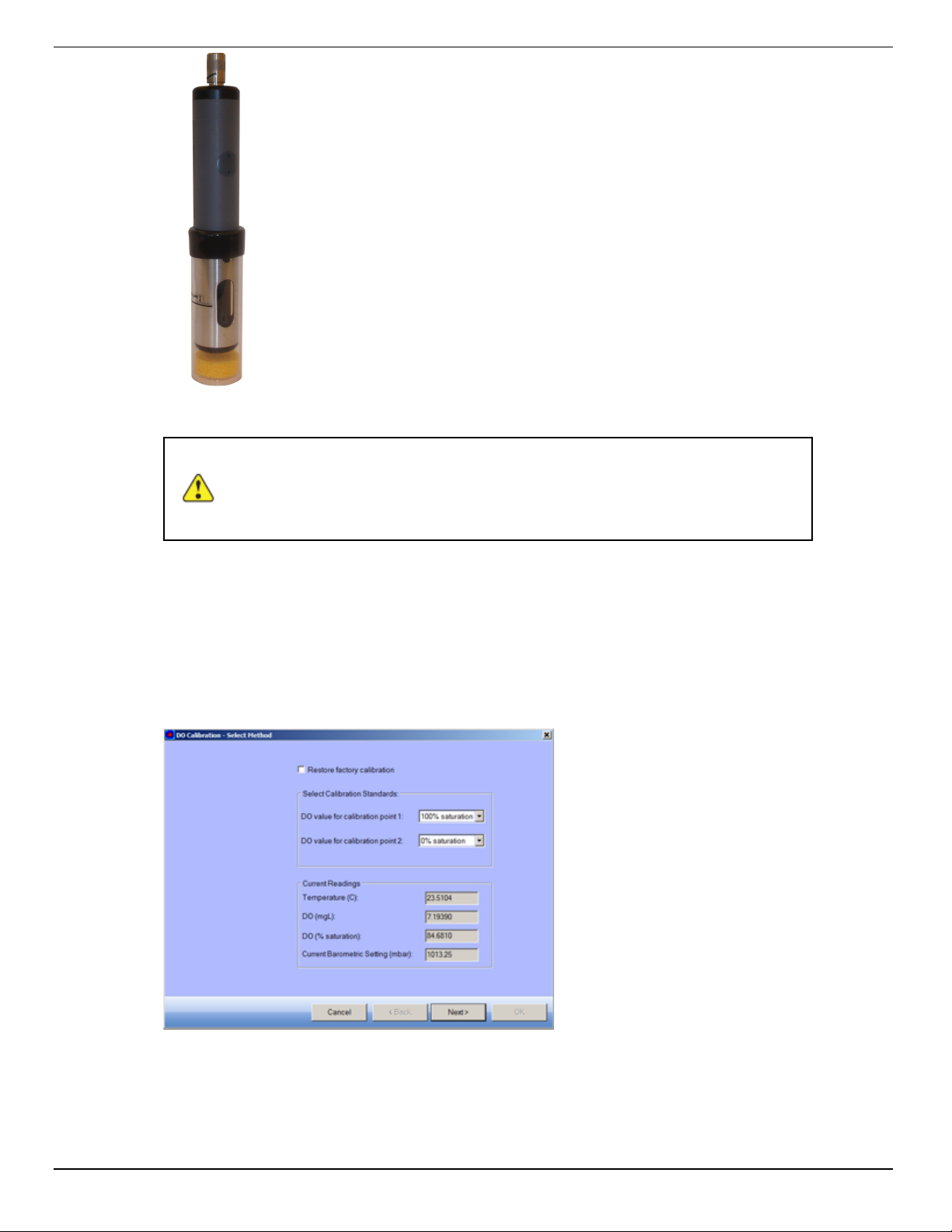
6. In the Comm Kit Software, select the Sensor Setup tab.
7. Select the RDO Dissolved Oxygen parameter.
8. Click Calibrate.
9. By default, 100% saturation is selected for the first point of the calibration. If you
intend to perform a 2-point calibration, also select 0% saturation from the drop-down
list. Otherwise, leave as “None.”
10. Click Next.
800-446-7488 9 www.in-situ.com
Page 10
11. Enter the barometric pressure or elevation at which the instrument will be deployed,
if necessary.
12. Click Next.
13. Click OK to start the calibration.
14. When the screen indicates that the calibration has reached stability, click Accept to
complete the calibration, or click to Cancel to return to the previous calibration
values.
Calibrate 0% Oxygen Saturation
1. If you selected to perform a 2-point calibration, you are prompted to set up the
solution for the second point of the calibration.
2. Remove the wet sponge from the cup.
3. Fill the calibration cup to the fill line with approximately 130 mL of fresh sodium
sulfite solution.
4. Completely submerge the RDO Sensor into the solution.
5. Click OK to start the calibration.
6. When the screen indicates that the calibration has reached stability, click Accept to
complete the calibration, or click Cancel to return to the previous calibration.
7. You can save or print the calibration report.
8. Click OK to complete the calibration.
9. Once calibration is complete, remove the instrument from the calibration cup and
rinse both thoroughly with clean water.
Conductivity Sensor Calibration
The conductivity sensor is calibrated with NIST®-traceable standards at the factory,
which provides a high degree of linearity across the entire operating range of 5 to
100,000 µS/cm. This sensor is capable of meeting its published specifications without
requiring additional calibration by the user. Most commercially available standards can
introduce a larger potential measurement error than the sensor’s initial factory
800-446-7488 10 www.in-situ.com
Page 11
calibration. User calibration is recommended only if you must conform to a standard
operating procedure or if the conductivity cell has undergone physical change (e.g.,
deposits on conductivity cell walls that cannot be removed or physical damage to the
conductivity cell walls).
1. Fill the calibration cup to the fill line with approximately 130 mL of the desired
calibration solution.
2. Place the calibration cap on the instrument slightly above the restrictor, and
carefully place the instrument in the solution taking care to not force the solution out
the top of the calibration cup.
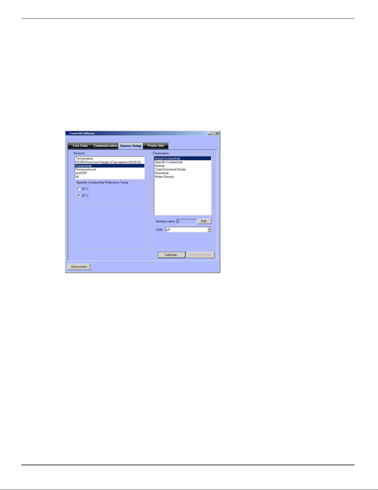
3. In the Comm Kit Software, select the Sensor Setup tab.
4. Select the Conductivity parameter.
5. Select either 20° C or 25° C as the reference temperature, as indicated by the
reference solution.
6. Click Calibrate.
800-446-7488 11 www.in-situ.com
Page 12
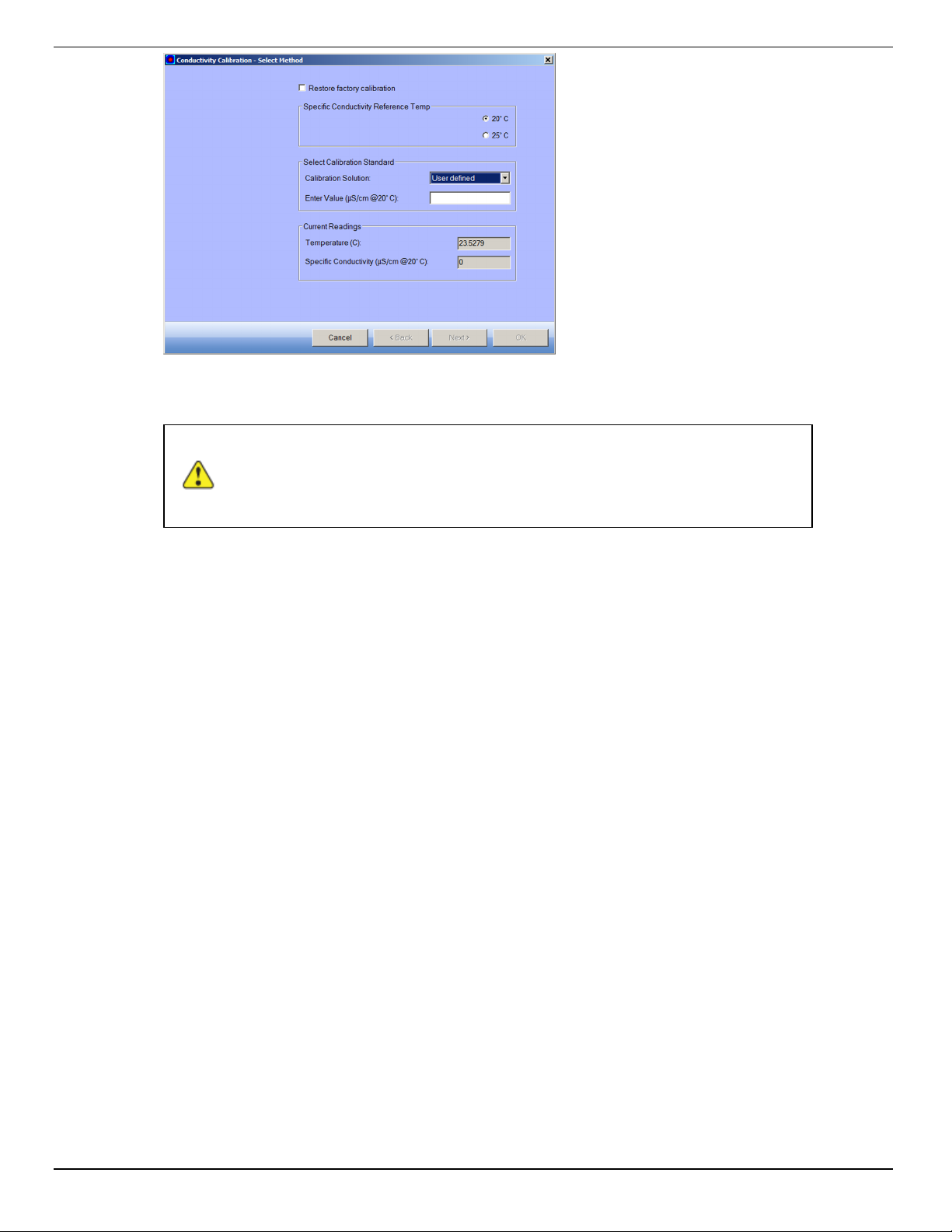
7. Select the appropriate calibration standard from the drop-down list. If you select
“User Defined,” enter the value of the solution.
Note: If you select 20° C as the reference temperature, you must
also select “User defined” and enter the value of the your
calibration standard.
8. Click Next.
9. Place the instrument into the calibration cup and allow time for the temperature to
stabilize.
10. Gently tap the sides of the calibration cup against the palm of your hand to remove
any bubbles in the conductivity cell. Visually inspect to ensure that all bubbles are
removed.
11. Click OK to start the calibration.
12. When the screen indicates that the calibration has reached stability, click Accept to
complete the calibration, or click Cancel to return to the previous calibration.
13. You can save or print the calibration report.
14. Click OK to complete the calibration.
15. Once calibration is complete, remove the instrument from the calibration cup and
rinse both thoroughly with clean water.
Pressure/Level
The pressure sensor has been factory calibrated with NIST standards to a greater
degree of accuracy than can be achieved in nearly any alternative setting. Therefore,
user calibration is not necessary for the pressure sensor.
800-446-7488 12 www.in-situ.com
Page 13
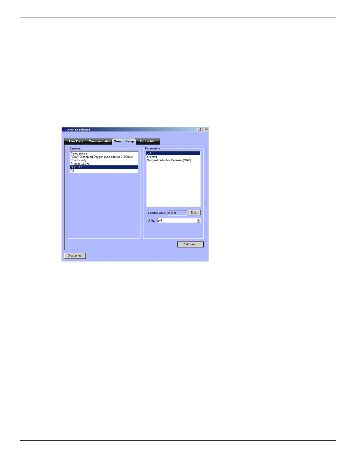
pH/ORP Sensor Calibration
Fill the calibration cup to the fill line with approximately 130 mL of the desired pH or
ORP calibration solution.
Place the calibration cap on the instrument slightly above the restrictor, and place the
instrument in the solution taking care to not force the solution out the top of the
calibration cup.
1. In the Comm Kit Software, select the Sensor Setup tab.
2. Select the pH/ORP parameter.
3. Click Calibrate.
4. Select Calibrate pH, or Calibrate ORP.
5. Click Next.
6. Select a value for the first calibration point. If you intend to perform a 2-point or 3point calibration, select the appropriate values as indicated on the label of the
calibration standard.
7. Click Next.
8. Place the instrument into the calibration cup and allow time for the temperature to
stabilize.
9. Click OK, to start the calibration.
10. When the screen indicates that the calibration has reached stability, click Accept to
complete the calibration for that calibration point, or click Cancel to return to the
previous calibration.
11. Follow the Wizard to continue through the remaining calibration points.
12. You can save or print the calibration report.
13. Click OK to complete the calibration.
800-446-7488 13 www.in-situ.com
Page 14

14. Once calibration is complete, remove the instrument from the calibration cup and
rinse both thoroughly with clean water.
15. Diagnostics and Factory Reset
16. The Probe Info Tab displays the software application version, probe type, and probe
serial number. This tab also allows contains access to Diagnostics and Factory
Reset options.
800-446-7488 14 www.in-situ.com
Page 15
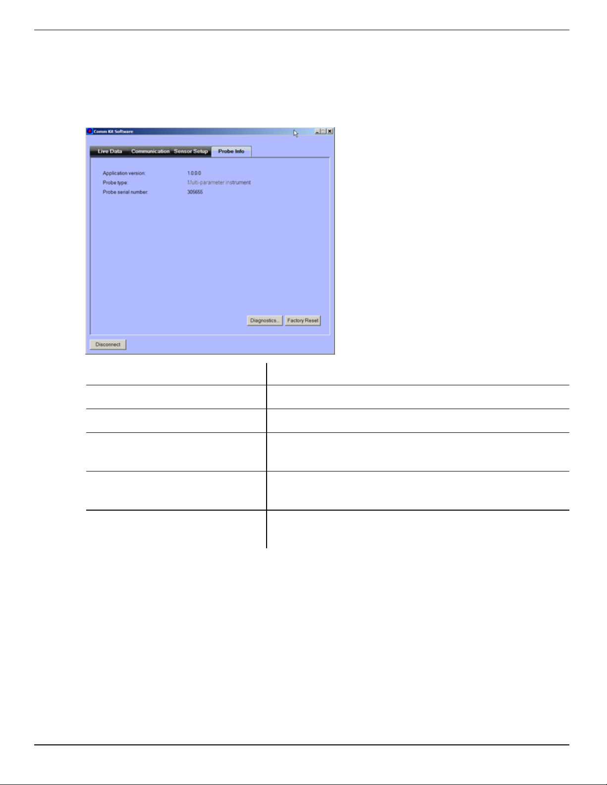
Diagnostics and Factory Reset
The Probe Info Tab displays the software application version, probe type, and probe
serial number. This tab also allows contains access to Diagnostics and Factory Reset
options.
Screen Element Purpose
Application version Comm Kit Software version
Probe type Instrument description
Probe serial number
Diagnostics
(button)
Factory Reset
(button)
Unique number engraved on the instrument at the
factory
Allows you to view the sensor calibration coefficients
and data regarding messages sent and received.
Enables you to reset the instrument to original factory
settings.
800-446-7488 15 www.in-situ.com
 Loading...