

Page 1
SERVICE MANUAL
Commercial Disposers
SS-50
SS-75
SS-100
SS-125
SS-150
SS-200
SS-300
SS-500
SS-750
SS-1000
Part No. F376-09L-76-02 © 2009
Page 2

Commercial Disposers
TABLE OF CONTENTS
GENERAL INFORMATION .................................................................................................................................... 3
SAFETY SIGNALS ....................................................................................................................................................... 3
COMMERCIAL DISPOSERS ....................................................................................................................................... 3
PRIOR TO SERVICE CALL ......................................................................................................................................... 3
AFTER COMPLETING SERVICE ................................................................................................................................ 3
COMMERCIAL DISPOSER
PARTS LIMITED WARRANTY ..................................................................................................................................... 4
SERIAL NUMBER DATE CODE .................................................................................................................................. 4
SPECIFICATIONS ..................................................................................................................................................... 5
COLD WATER FLOW & DRAIN LINE DIAMETER ...................................................................................................... 5
DIMENSIONS .............................................................................................................................................................. 5
ELECTRICAL REQUIREMENTS ................................................................................................................................. 7
RECOMMENDED INSTALLATION .............................................................................................................................. 8
REMOVING DISPOSER .............................................................................................................................................. 9
INSTALLING DISPOSER ............................................................................................................................................. 9
PREPARATION FOR REPAIR .............................................................................................................................. 9
COMMON REPAIR AREAS ....................................................................................................................................... 10
TERMINAL BOX & TRIM BAND .................................................................................................................................11
GRINDING CHAMBER .......................................................................................................................................... 12
REPLACING WATER INLET ...................................................................................................................................... 12
REPLACING SHREDDER GASKET ......................................................................................................................... 12
REPLACING STATIONARY SHREDDER .................................................................................................................. 13
REPLACING ROTATING SHREDDER ...................................................................................................................... 14
REPAIRING UPPER END BELL ASSEMBLY ........................................................................................................... 15
UPPER END BELL (UEB) .................................................................................................................................... 15
ELECTRICAL REPAIRS ....................................................................................................................................... 18
OVERLOAD PROTECTOR ........................................................................................................................................ 18
CAPACITOR .............................................................................................................................................................. 19
BOTTOM COVER AND FAN ...................................................................................................................................... 20
LOWER END FRAME (LEF) ...................................................................................................................................... 21
REPLACING START SWITCH
(1 PHASE MODELS) ................................................................................................................................................. 21
STATOR ..................................................................................................................................................................... 22
MOTOR LEADS CONNECTIONS .............................................................................................................................. 23
WIRING DIAGRAMS .............................................................................................................................................. 24
TROUBLESHOOTING ........................................................................................................................................... 27
EXPLODED VIEWS & PARTS LISTS .............................................................................................................. 32
Service Manual i
Page 3

Commercial Disposers
NOTES
_________________________________________________________________________________________________________
_________________________________________________________________________________________________________
_________________________________________________________________________________________________________
_________________________________________________________________________________________________________
_________________________________________________________________________________________________________
_________________________________________________________________________________________________________
_________________________________________________________________________________________________________
_________________________________________________________________________________________________________
_________________________________________________________________________________________________________
_________________________________________________________________________________________________________
_________________________________________________________________________________________________________
_________________________________________________________________________________________________________
_________________________________________________________________________________________________________
_________________________________________________________________________________________________________
_________________________________________________________________________________________________________
_________________________________________________________________________________________________________
_________________________________________________________________________________________________________
_________________________________________________________________________________________________________
_________________________________________________________________________________________________________
_________________________________________________________________________________________________________
_________________________________________________________________________________________________________
_________________________________________________________________________________________________________
_________________________________________________________________________________________________________
_________________________________________________________________________________________________________
_________________________________________________________________________________________________________
_________________________________________________________________________________________________________
_________________________________________________________________________________________________________
_________________________________________________________________________________________________________
_________________________________________________________________________________________________________
_________________________________________________________________________________________________________
_________________________________________________________________________________________________________
_________________________________________________________________________________________________________
_________________________________________________________________________________________________________
_________________________________________________________________________________________________________
_________________________________________________________________________________________________________
_________________________________________________________________________________________________________
_________________________________________________________________________________________________________
_________________________________________________________________________________________________________
_________________________________________________________________________________________________________
ii
Service Manual
Page 4
Safety Signals
This symbol indicates potential personal injury hazards.
Obey all safety messages accompanying this symbol to
avoid possible injury or death.
Commercial Disposers
GENERAL INFORMATION
DANGER
CAUTION indicates a potentially hazardous
DANGER indicates an imminently hazardous
situation which, if not avoided, will result in
death or serious injury.
WARNING indicates a potentially hazardous
situation which, if not avoided, could result in
death or serious injury.
situation which, if not avoided, may result in
minor or moderate injury.
Commercial Disposers
InSinkErator® manufactures commercial food waste disposers
with motors ranging from 1/2 horsepower through 10 horsepower.
The basic assembly of all SS Series commercial disposers is identical. However, electrical connections vary depending upon the
disposer specications, power supply, and electrical controls.
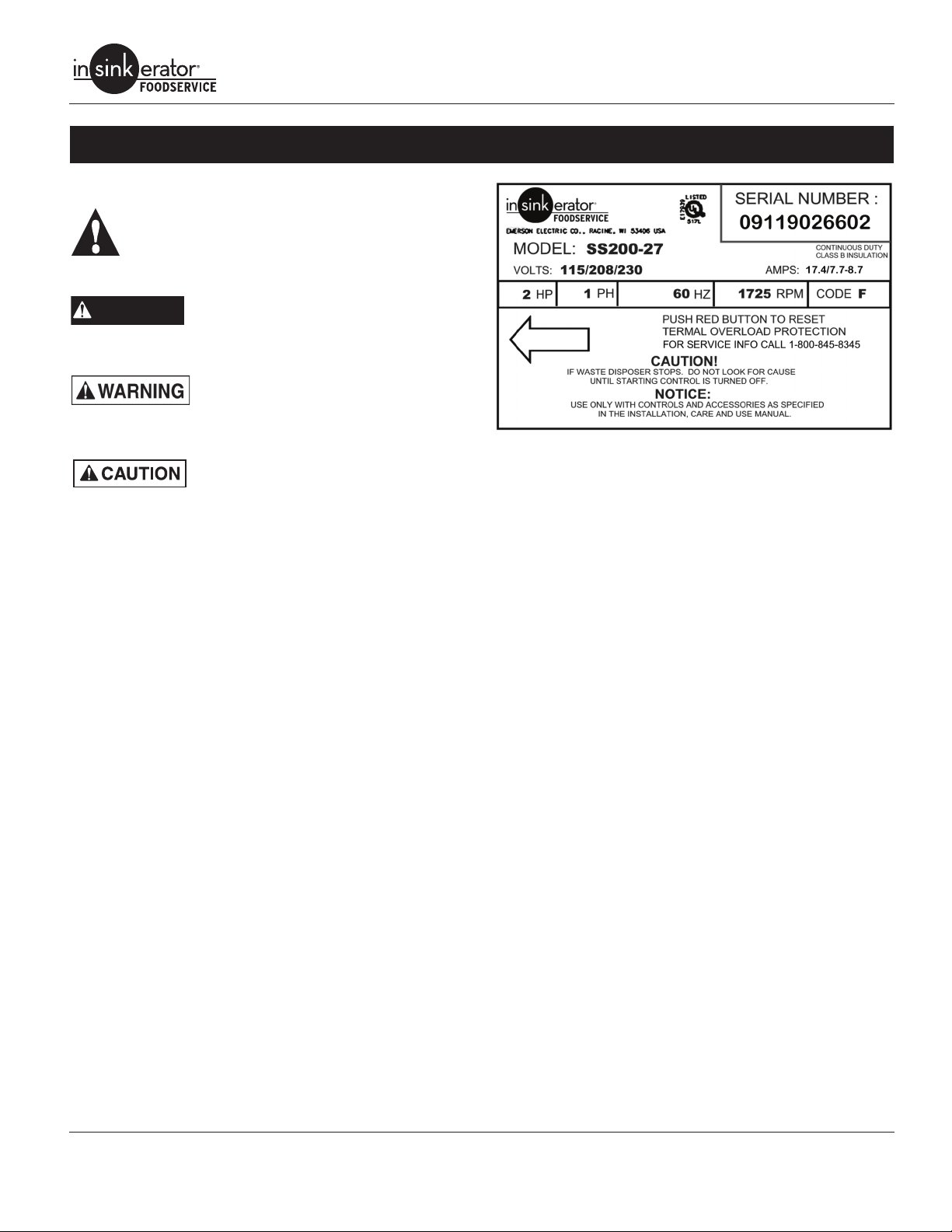
Specication Decal
The specication decal (Figure 1) located on the motor trim cover
indicates
• complete model number (example - SS150-24)
• serial number (includes manufactured date)
• amperage
• voltage
• phase
• horsepower.
NOTE: The correct part sheet (as designated by the complete
model number) must be referenced to order replacement parts.
Figure 1. Specication Decal
Prior to Service Call
• Obtain the model number, serial number, voltage and phase
from the customer to prepare for the service call.
• Date of installation.
• Obtain the service history of the disposer.
• Make sure the customer has tried resetting the overload protector and has checked for foreign objects jammed in the
grind chamber (see “Troubleshooting” on page 25).
• Before troubleshooting for mechanical problems, determine if
the problem is electrical:
• To determine if the problem is in the switch or the dispos-
er, bypass all electrical starting and/or electrical controls
and run the disposer direct.
• Make sure the disposer electrical specications match
the electric power supply.
• Make sure the motor lead connections are correct for the
corresponding power supply and starting controls.
• Determine if there are electrical problems with other
kitchen appliances. This may indicate a problem in the
building’s electrical circuitry.
After Completing Service
Test the disposer for proper operation and ensure that the ttings
are secure and do not leak.
Service Manual 1
Page 5
Commercial Disposers
Commercial Disposer
Limited Warranty
InSinkErator® commercial disposers are warranted against defects
in material and workmanship for one year from the date of installation. The warranty includes parts and labor, provided the service is
performed by an InSinkErator Factory Authorized Service Center.
This warranty does not apply if failure is due to :
• Faulty or improper electrical installation
• Faulty or improper plumbing installation
• Product abuse or misuse
• Accidental damage
• Grinding elements jammed by foreign objects
• Clogged drain lines
• Unit improperly sized or improper water ow (as specied in
the Disposer Sizing Chart and Recommended Cold Water
Flow Chart in this manual..
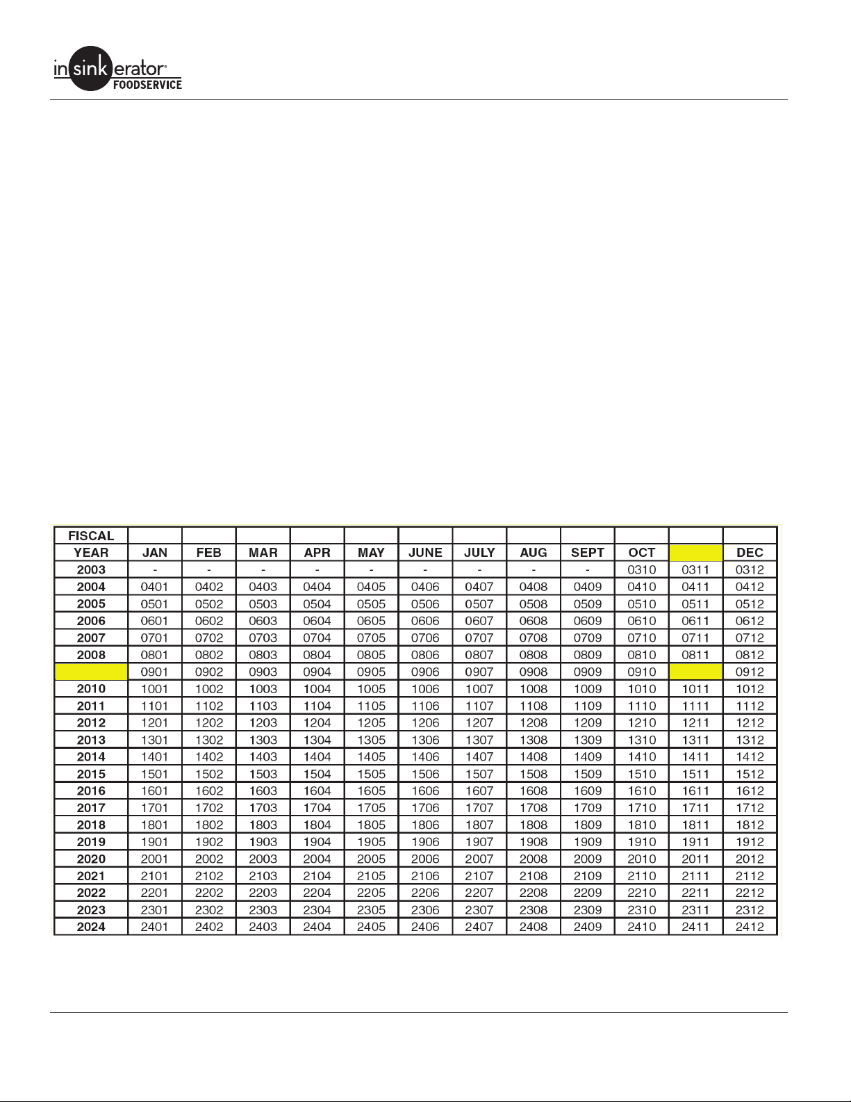
Serial Number Date Code
Example: 09110000000 09 = Year of Manufacture
11 = Month of Manufacture
Commercial Disposer Parts Limited Warranty
Replacement parts installed on OUT OF WARRANTY dispos-
ers are covered (parts and labor) for 90 days from the date
the parts are installed, provided the service is performed by an
InSinkErator Factory Authorized Service Center. To receive credit,
the Service Agency must provide a copy of the service invoice
given to the customer as a receipt for the replacement part.
2009
09
2
Service Manual
Page 6
SPECIFICATIONS
Cold Water Flow & Drain Line Diameter
Commercial Disposers
Disposer
SS-50 3 (11) 1-1/2" (38)
SS-75 3 (11) 1-1/2” (38)
SS-100 5 (19) 1-1/2”(38)
SS-125 5 (19) 1-1/2” (38)
SS-150 7 (26) 2" NPT (51)
SS-200 7 (26) 2” NPT (51)
SS-300 8 (30) 3" NPT (51)
SS-500 8 (30) 3” NPT (51)
SS-750 10 (38) 3” NPT (51)
SS-1000 10 (38) 3” NPT (51)
Water Flow
GPM (LPM)
Drain Line Diameter
Inches (MM)
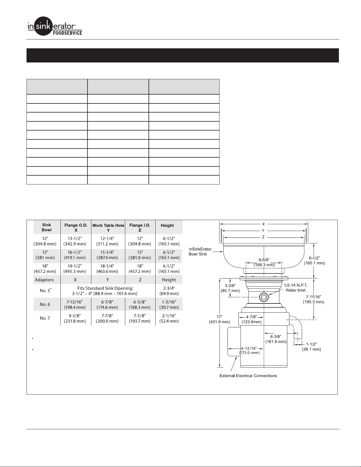
Dimensions
IMPORTANT: Use the following dimension charts for adaptor height in place of InSinkErator sink bowl height when mounting directly
to a sink. Dimensions - Models SS-50, SS-75, SS-100 & SS-125.
NOTE:
Adaptors are available upon request for all competitor
sink bowls or cones.
Please have sink/bowl cone type with the necessary
dimensions when ordering adaptors.
* It is recommended to add legs (Part No.11757C) with No. 5 Mounting Assembly.
Figure 2. Dimensions - Models SS-50, SS-75, SS-100 & SS-125
Service Manual 3
Page 7
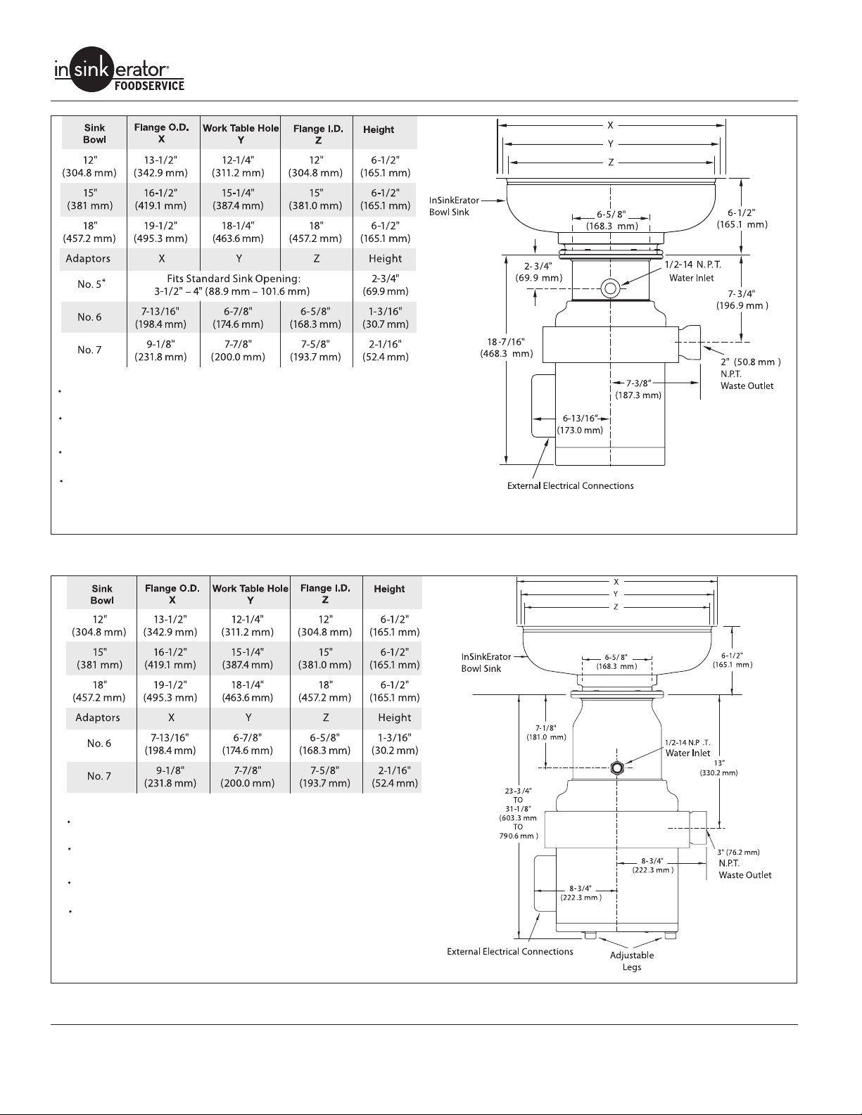
NOTE:
Adaptors are available upon request for all competitor
sink bowls or cones.
Please have sink/bowl cone type with the necessary
dimensions when ordering adaptors.
Also available as a short body model. Reduces overall
height of disposer by 1” (25.4 mm).
Legs shipped in carton with unit. Assembly required prior to unit installation.
* It is recommended to add legs (Part No.11757C) with No. 5 Mounting Assembly.
Commercial Disposers
Figure 3. Dimensions - Models SS-150 & SS-200
NOTE:
Adaptors are available upon request for all competitor
sink bowls or cones.
Please have sink/bowl cone type with the necessary
dimensions when ordering adaptors.
Also available as a short body model. Reduces overall
height of disposer by 3” (76.2 mm).
Unit shipped with legs installed from factory. Adjustment
required at time of unit installation.
Figure 4. Dimensions - Models SS-300, SS-500, SS-750 & SS1000
4
Service Manual
Page 8
Commercial Disposers
Electrical Requirements
The electrical wiring on disposers shipped from the factory are
not connected for a specic voltage. Refer to the Standard Motor
Connection Wiring Diagram attached to the inside of the disposer
terminal box cover for the correct voltage connections.
Standard disposer voltages are:
• 115/208/230 volts for single phase electrical power
• 208/230/460 volts for three phase electrical power
-26 115/208-230V, 60Hz, 1 Ph, 8.4/4.0/4.2 amps, UL
SS-50
1/2 H.P.
SS-75
3/4 HP
SS-100
1 H.P.
SS-125
1-1/4 H.P.
SS-150
1-1/2 H.P.
SS-200
2 H.P.
SS-300
3 H.P.
SS-500
5 H.P.
-27 208-230/460V, 60Hz, 3 Ph, 2.0/2.1/1.1 amps, UL
-28 115/208-230V, 60Hz, 1 Ph. 8.4/4.0/4.2 amps, CSA
-29 208-230/460V, 60Hz, 3 Ph, 2.0/2.1/1.1 amps, CSA
-27 115/208-230V, 60Hz, 1 Ph, 10.0/4.3/5.0 amps, UL
-28 208-230/460V, 60Hz, 3 Ph, 2.0/2.4/1.2 amps, UL
-29 115/208-230V, 60Hz, 1 Ph, 10.4/4.3/5.0 amps, CSA
-30 208-230/460V, 60Hz, 3 Ph, 2.0/2.4/1.2 amps, CSA
-28 115/208-230V, 60Hz, 1 Ph, 11.6/5.1/5.7 amps, UL
-29 208-230/460V, 60Hz, 3 Ph, 2.2/3.0/1.5 amps, UL
-30 115/208-230V, 60Hz, 3 Ph, 11.6/5.1/5.7 amps, CSA
-31 208-230/460V, 60Hz, 3 Ph, 2.2/3.0/1.5 amps, CSA
-25 115/208-230V, 60Hz, 1 Ph, 10.6/4.5/5.3 amps, UL
-26 208-230/460V, 60Hz, 3 Ph, 3.5/4.0/2.0 amps, UL
-27 15/208-230V, 60Hz, 1 Ph, 10.6/4.5/5.3 amps, CSA
-28 208-230/460V, 60Hz, 3 Ph, 3.5/4.0/2.0 amps, CSA
-34 115/208-230V, 60Hz, 1 Ph, 12.2/5.7/6.1, amps, UL
-36 208-230/460V, 60 Hz, 3 Ph, 3.2/4.6/2.3 amps, UL
-37 208-230/460V, 60 Hz, 3 Ph, 3.2/4.6/2.3 amps, CSA
-38 115/208-230V,, 60 Hz, 1 Ph, 12.2/5.7/6.1 amps, UL, short body
-39 208-230/460V, 60 Hz, 3 Ph, 3.2/4.6/2.3 amps, UL, short body
-35 115/208-230V, 60 Hz, 1 Ph, 12.2/5.7/6.1 amps, CSA
-27 115/208-230V, 60 Hz, 1 Ph, 17.4/7.7/8.7 amps, UL
-29 208-230/460V, 60 Hz, 3 Ph, 3.3/5.0/2.5 amps UL
-31 115/208-230V, 60 Hz, 1 Ph, 17.4/7.7/8.7 amps, UL, short body
-32 208-230/460V, 60 Hz, 3 Ph, 3.3/5.0/2.5 amps, UL, short body
-28 115/208-230, 60 Hz, 1 Ph, 17.4/7.7/8.7 amps, CSA
-30 208-240/460V 60Hz, 3 Ph, 3.3/5.0/2.5 amps, CSA
-25 208-230/460V, 60 Hz, 3 Ph, 6.0/7.4/3.7 amps, UL
-27 208-230/460V, 60 Hz, 3 Ph, 6.0/7.4/3.7 amps, UL, short body
-26 208-230/460V, 60 Hz, 3 Ph, 6.0/7.4/3.7 amps, CSA
-28 208-230/460V, 60 Hz, 3 Ph, 8.4/8.8/4.4 amps, UL
-30 208-230/460V, 60 Hz, 3 Ph, 8.4/8.8/4.4 amps, UL, short body
-29 208-230/460V, 60 Hz, 3 Ph, 8.4/8.8/4.4 amps, CSA
NOTE: All amp ratings denote amp draw during a grind load.
NOTE: The disposer motor phase and voltage must be the same
as the line or power supply.
DANGER
ELECTRIC SHOCK! The disposer must be
permanently grounded.
Service Manual 5
Page 9
Commercial Disposers
SS-750
7-1/2 H.P.
SS-1000
10 H.P.
-13 208-230/460V, 60 Hz, 3 Ph, 9.7/12.4/6.2 amps, UL
-15 208-230/460V, 60 Hz, 3 Ph, 9.7/12.4/6.2 amps, UL, short body
-14 208-230/460V, 60 Hz, 3 Ph, 9.7/12.4/6.2 amps, CSA
-10 208-230/460V, 60 Hz, 3 Ph, 11.0/13.0/6.5 amps, UL
-12 208-230/460V, 60 Hz, 3 Ph, 11.0/13.0/6.5 amps, UL, short body
-11 208-230/460V, 60 Hz, 3 Ph, 11.0/13.0/6.5 amps, CSA
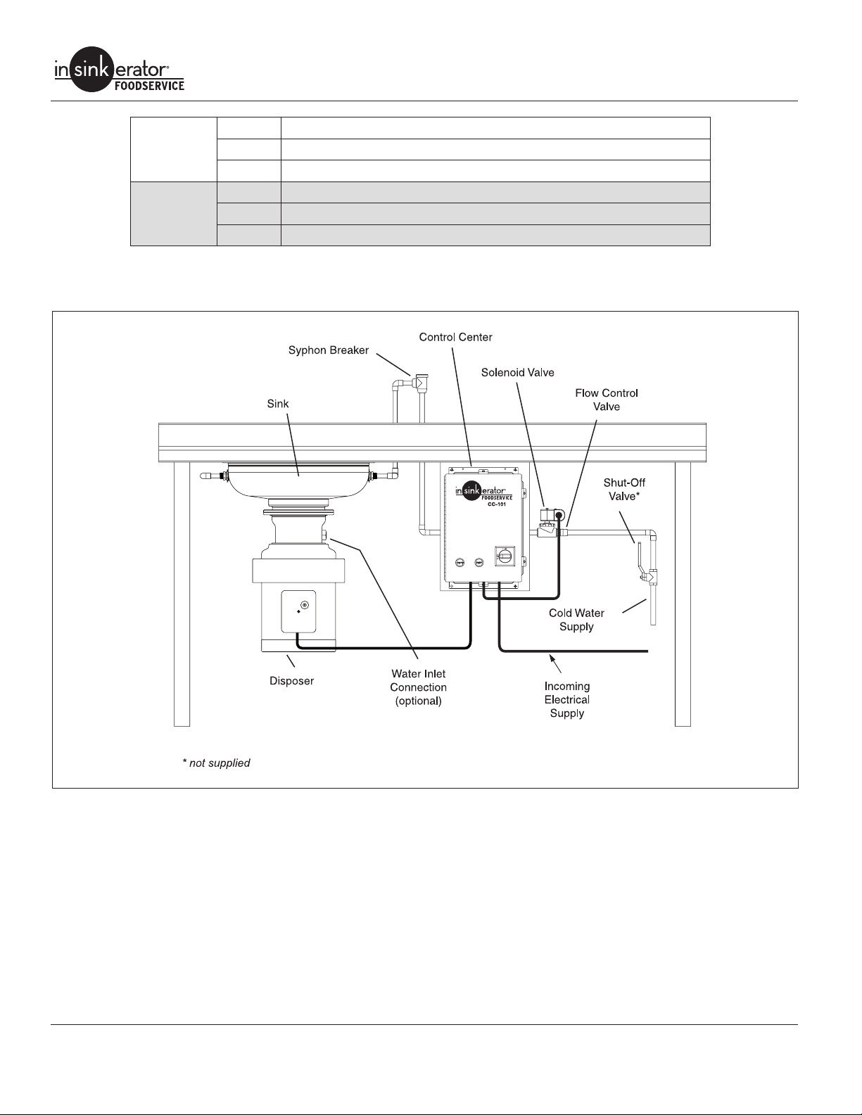
Recommended Installation
Figure 5. Recommended Installation
6
Service Manual
Page 10
PREPARATION FOR REPAIR
Commercial Disposers
DANGER
ELECTRIC SHOCK! Turn off water and
electrical supply. Discharge capacitor with
1000 ohm jumper wire (1 Phase only). Do
not use a screwdriver to discharge or
capacitor may be damaged.
Removing Disposer
1. Turn off electrical supply and water supply to disposer.
2. Disconnect cold water connection from disposer body water
inlet (if connected).
3. Disconnect waste line from disposer.
4. Remove terminal box retaining screw and terminal box cover.
See “Terminal Box & Trim Band” on page 9. Mark motor lead
wires and electrical supply wires, then disconnect wires and
grounding wire from disposer.
NOTE: Make sure sink can bear weight of disposer before legs
are loosened. In some cases, support disposer before loosening
or removing legs.
5. If equipped with legs and legs interfere with removing disposer from mounting ange, pull O-ring down disposer leg,
turn each leg clockwise to raise legs and gain oor clearance.
6. Remove disposer from mounting ange by turning disposer
or loosening bolts as necessary (depending on mounting
ange).
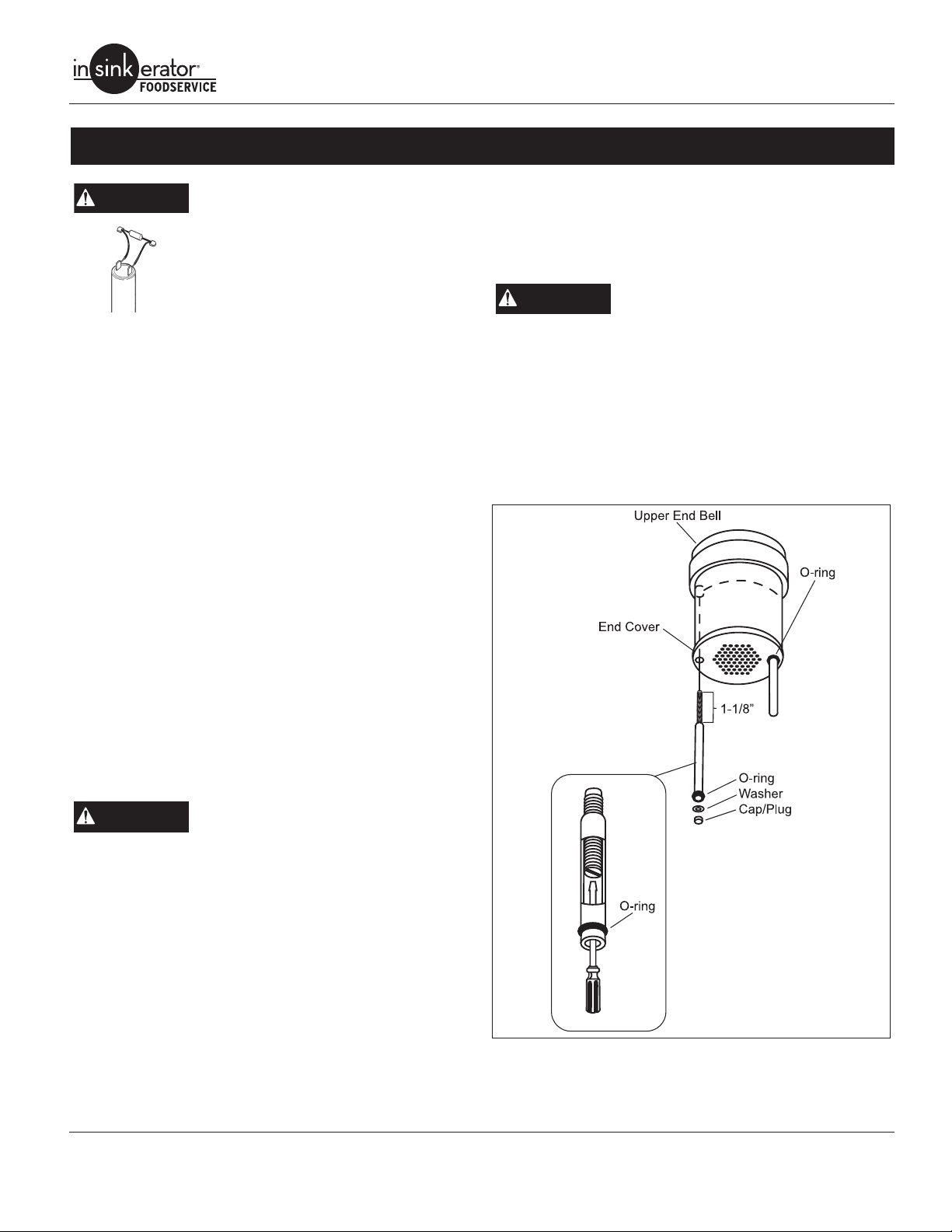
7. To remove legs, remove black cap plug from bottom of support leg (Figure 6). Insert slotted screwdriver into open end of
leg support tube and turn stud counterclockwise until free of
upper end bell. Pull leg from disposer.
4. Connect electrical supply wires to the motor leads. Reference the wiring diagram attached to the inside of the terminal
box or the Wiring Diagrams section of the Disposer Control
Center Installation manual.
5. Reinstall terminal box.
DANGER
6. Connect waste line to disposer.
7. Connect cold water supply to disposer body water inlet (if previously installed).
8. Turn on electrical and water supply.
9. Test the disposer to ensure the cutting elements revolve
and the water ows automatically. Make sure the disposer is
securely mounted and does not leak from any of the connections.
ELECTRIC SHOCK! Make sure electrical
wires are not pinched or damaged when
installing terminal box cover.
Installing Disposer
DANGER
1. If unit was equipped with legs, insert leg assemblies through
end cover guide holes. Insert screwdriver into open end of leg
support tube and turn stud clockwise to install. Install O-ring,
washer and cap to each leg (Figure 6).
NOTE: On models SS-150 thru SS-200, legs are optional and recommended where the disposer is mounted to a thin gauge sink
(16 gauge minimum), dish table, using a #5 mounting assembly
or non-InSinkErator mounting adaptors. On models SS-300 and
above, legs are factory installed and recessed on the unit.
2. Attach disposer to the mounting assembly by positioning in
mounting ange and turning disposer into ange or tightening
bolts (depending on specic mounting).
3. Adjust legs so unit is supported evenly. Push O-ring up ush
with bottom of unit.
Service Manual 7
ELECTRIC SHOCK! Turn off water and
electrical supply. Discharge capacitor
with jumper wire (1 Phase only).
Figure 6. Disposer Leg
Page 11
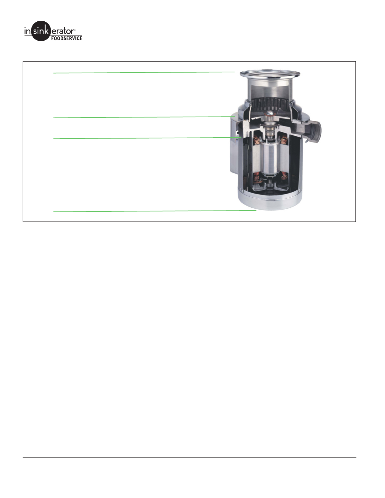
Common Repair Areas
GRIND CHAMBER
• Stationary Shredder Gasket
• Stationary Shredder
• Rotating Shredder
UPPER END BELL (UEB)
• Seals & Bearings
ELECTRICAL
• Overload
• Capacitor
• Stator
• Rotor & Centrifugal Switch
• Lower End Frame (LEF)
Commercial Disposers
Figure 7. Common Repair Areas
8
Service Manual
Page 12
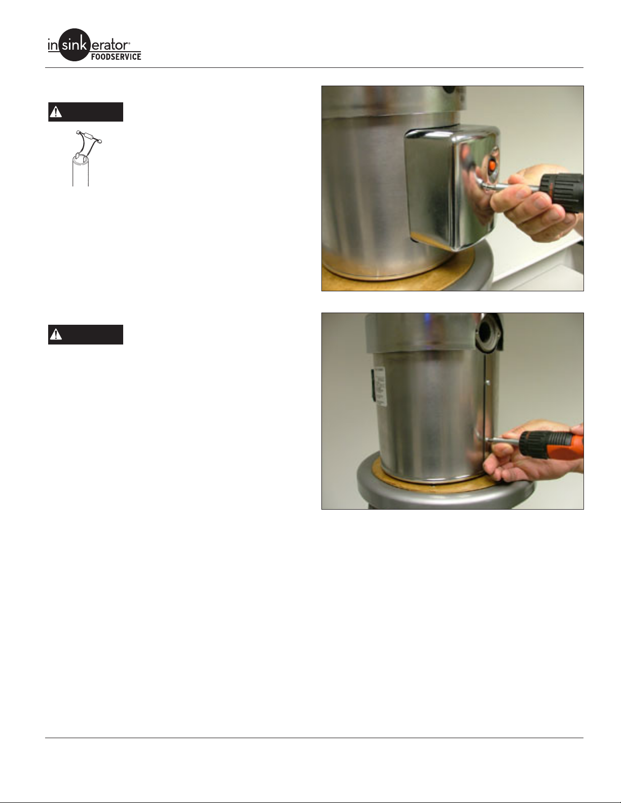
Terminal Box & Trim Band
Commercial Disposers
DANGER
NOTE: Terminal box and trim band are removed for all repairs
except overload and start capacitor.
ELECTRIC SHOCK! Turn off water and
electrical supply. Discharge capacitor with
1000 ohm jumper wire (1 Phase only). Do
not use a screwdriver to discharge or capacitor may be damaged.
Removal
1. Remove screw and terminal box (Figure 8).
2. Remove two screws securing trim band (Figure 9).
3. Spread the trim seam. While pivoting trim band upward and
forward, slip band over terminal box bracket and remove
band from disposer.
Installation
DANGER
1. Insert trim band onto unit. Secure with two screws and
tighten.
2. Install terminal box with overload protector positioned through
rubber grommet. Take care not to pinch lead wires in terminal
box.
3. Secure with screw.
ELECTRIC SHOCK! Make sure electrical
wires are not pinched or damaged when
installing terminal box cover
Figure 8. Terminal Box
Figure 9. Trim Band
Service Manual 9
Page 13
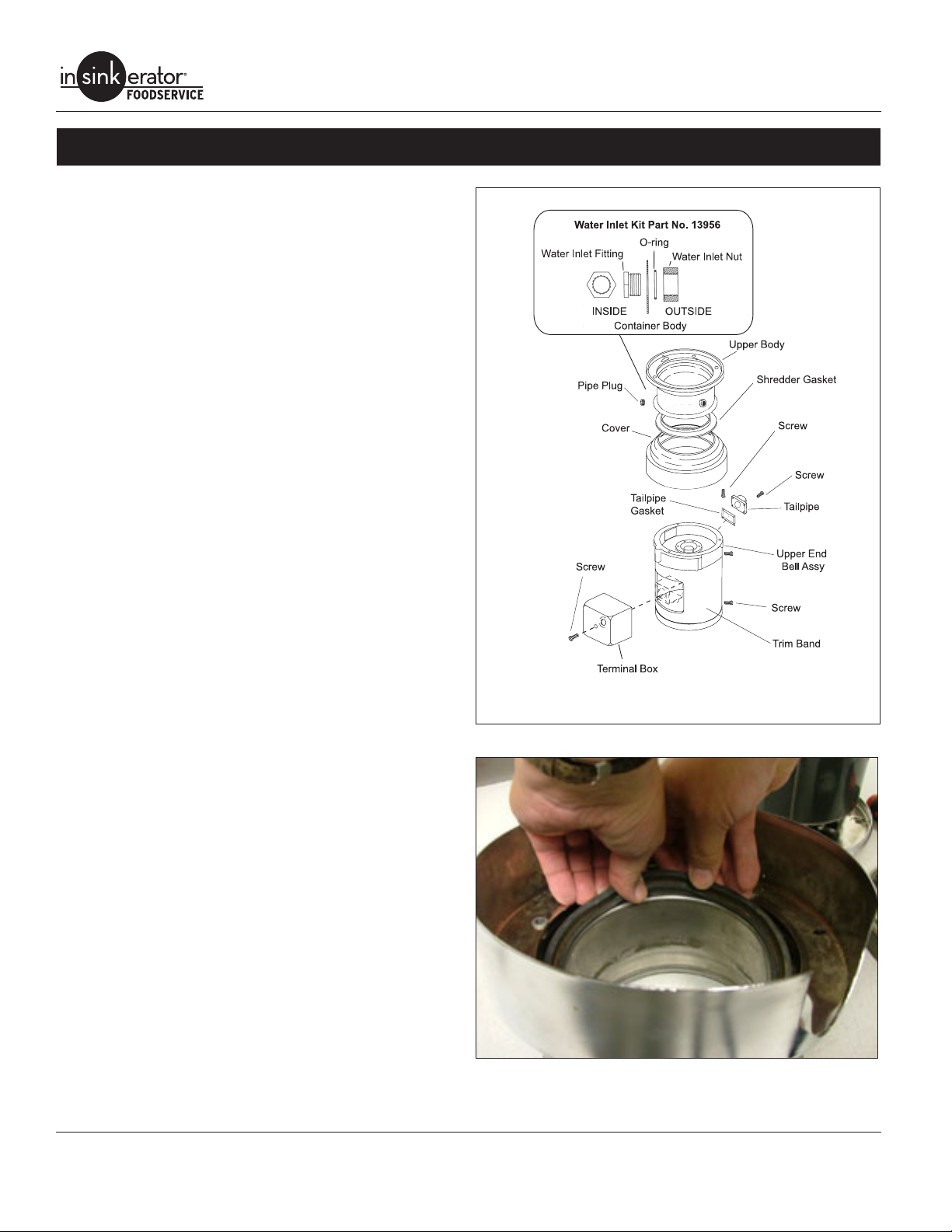
GRINDING CHAMBER
Replacing Water Inlet
NOTE: It is not necessary to remove the disposer to repair water
inlet.
Water Inlet Kit part number is 13956.
1. Using a wrench, remove water inlet from upper body (Figure
10).
2. Remove any burrs on water inlet hole.
3. Wrap Teon tape around new water inlet tting and insert
tting through water inlet hole from inside of upper body.
4. Place O-ring in groove in water inlet nut. A small amount of
grease may be used to hold O-ring in place during installation.
5. From outside of body, attach water inlet nut to water inlet tting. Tighten nut with wrench.
NOTE: Water inlet tting and nut are joined with a left-hand thread.
Commercial Disposers
Replacing Shredder Gasket
1. Remove disposer. See “Removing Disposer” on page 7.
2. Remove screws securing tailpipe and gasket from upper end
bell assembly (Figure 10).
3. Remove terminal box and trim band (Figure 10).
4. Remove screws securing body and cover assembly to upper
end bell assembly (Figure 10).
5. Lift cover and upper body assembly off upper end bell
assembly
6. Separate the upper body assembly from the cover.
7. Remove old gasket. Install new gasket to bottom edge of upper body (Figure 11).
8. Place cover over upper body.
9. Place cover and upper body assembly onto upper end bell
assembly. There are two tabs on the inside of the cover.
These tabs t into the two side grooves on the upper end bell
with the waste outlet aligned with the waste outlet cutout.
10. Secure in place with screws.
11. Install trim band and terminal box. See “Terminal Box & Trim
Band” on page 9.
12. Re-install tailpipe gasket and tailpipe using screws (Figure
10).
13. Install disposer. See “Installing Disposer” on page 7.
Figure 10. Cover and Upper Body Assembly
10
Figure 11. Replacing Shredder Gasket
Service Manual
Page 14
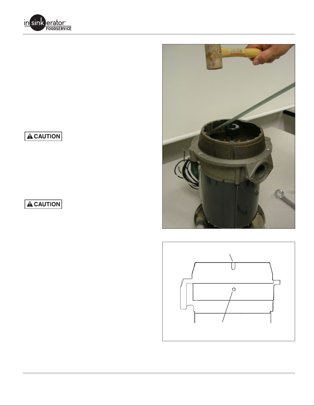
Replacing Stationary Shredder
Removal
1. Remove disposer. See “Removing Disposer” on page 7.
2. Remove cover and upper body assembly. Perform steps 2 – 5
under “Replacing Shredder Gasket” on page 10.
3. Lubricate the full outside diameter of the shredder ring with
penetrating oil.
4. Place a 1”D x 1-1/4”L long piece of pipe or similar sized hex
socket over rotating shredder nut (Figure 12).
5. Using a 5/16” thick at bar, rest bar on top of pipe or socket
with at end under shredder teeth. Strike jam release bar with
a soft non-metallic mallet (rawhide, nylon, leather, wood) to
break the seal and remove stationary shredder.
Do not strike stationary shredder or
shredder could be damaged.
Installation
1. Clean old silicone and dirt from upper end bell.
2. Apply water resistant silicone sealant around bottom of stationary shredder.
3. Place stationary shredder on upper end bell, aligning one
stationary shredder groove with upper end bell weep hole
(Figure 13). Strike stationary shredder rmly on alternate
sides with soft mallet until securely seated.
Do not use metal hammer or die cast
stationary shredder will break.
4. Turn rotating shredder by hand and make sure it rotates
freely.
5. Install cover and upper body. Perform steps 8–13 under
“Replacing Shredder Gasket” on page 10.
Commercial Disposers
Figure 12. Removing Stationary Shredder
Stationary Shredder Groove
Weep Hole
Figure 13. Aligning Stationary Shredder
Service Manual 11
Page 15

Replacing Rotating Shredder
Removal
1. Remove disposer. See “Removing Disposer” on page 7.
2. Remove stationary shredder. See “Replacing Stationary
Shredder” on page 11.
3. Lubricate shredder nut and shaft threads with penetrating oil.
4. Secure rotating shredder with a vice-grips or channel lock pliers and remove rotating shredder nut using a socket or box
wrench (Figure 14).
5. Place gear puller onto rotating shredder as shown (Figure
15).
Do not attempt to use gear puller to
remove the shredder without following
step 5. Tighten the puller until it creates
resistance on the rotating puller, then
proceed to step 6.
6. Tighten puller until snug. Tap around shredder hub 6-8 times.
Tighten puller 1/4 turn (maximum) and repeat. Shredder will
release from shaft after a number of repititions.
Installation
1. Place rotating shredder on shaft, aligning shredder keyways
with shaft keys. Tap with a soft mallet until seated.
2. Install ber washer, steel washer and self-locking hex mounting nut (Figure 16).
3. Hold rotating shredder with vise-grips or channel lock and
tighten mounting nut with socket or box wrench (Figure 14).
4. Install stationary shredder. Perform Installation procedure under See “Replacing Stationary Shredder” on page 11.
5. Install disposer. See “Installing Disposer” on page 7.
Commercial Disposers
Figure 14. Rotating Shredder Nut
12
Figure 15. Removing Rotating Shredder
Nut
Washer
Fiber Washer
Rotating Shredder
Upper End Bell
Figure 16. Installing Rotating Shredder
Service Manual
Page 16

UPPER END BELL (UEB)
Repairing Upper End Bell Assembly
1. Remove disposer. See “Removing Disposer” on page 7.
2. Turn unit right side up and remove body and upper cover assembly, stationary shredder and rotating shredder. See “Replacing Rotating Shredder” on page 12.
3. Turn unit upside down and remove lower cover, fan and stator. See “Removing the Stator” on page 20.
4. Remove two woodruff keys (one each side) from rotor shaft
and remove shield and spacer sleeve (Figure 17).
5. Remove screws securing seal assembly to upper end bell.
Work at head screwdriver under seal lip and pry up to remove seal assembly (Figure 18).
6. Remove third woodruff key from rotor shaft. Slide O-ring and
slinger off rotor shaft (Figure 19).
Commercial Disposers
Figure 17. Spacer Sleeve
Figure 18. Seal
Figure 19. O-ring and Slinger
Service Manual 13
Page 17

7. Carefully remove rotor shaft from upper end bell (Figure 22).
NOTE: Do not remove lower bearing or centrifugal switch
(1 Phase only) from rotor. If centrifugal switch is damaged,
rotor shaft assembly must be replaced
If bearing is damaged, press bearing off rotor shaft, supporting rotor shaft by the bearing. Press new bearing onto shaft
until fully seated on shaft groove.
8. Remove water and oil seal, bearing set and spacer from motor side of UEB (Figure 20).
NOTE: On SS-300, SS-500, SS-750 and SS-1000 units, remove steel thrust washer.
Do not attempt to remove large snap ring
from center of upper end bell. Snap ring
cannot be removed without damaging
upper end bell.
9. Using wood block and mallet, knock both bearing races out
from UEB.
10. Clean upper end bell of all grease, dirt and sealant. Clean
outside diameter of bearing cup and wipe dry with clean rag
(Figure 21).
11. Coat inner wall of bearing cavity with #242 Loctite and fully
seat new race (bevel side outwards). Turn end bell over and
repeat for other side.
12. Lubricate new bearing pack with Texaco RV1939 or equivalent and install bearing pack into cavity on motor side of UEB.
13. Place new water & oil seal squarely into end bell recess (motor side). Using a wood block or soft mallet, tap seal into end
bell recess until it is ush with casting.
NOTE: On SS-300 and SS-500 (serial # 70,000 and above)
and SS-750 and SS-1000 units, install steel thrust washer.
14. Carefully insert rotor assembly into UEB from motor side.
15. Install stator, lower end frame, fan and bottom cover.
See “Stator” on page 20.
16. Install slinger and O-ring (Figure 19). O-ring should t snug
against slinger.
17. Install lower woodruff key into shaft keyway.
18. Install spacer sleeve with channel tting over O-ring, aligning
sleeve notch with woodruff key (Figure 22).
19. Coat machined face and groove (with 6 holes) of
upper end bell with water proof silicone sealant (Figure 21).
20. Install seal assembly and secure with screws (Figure 18).
21. Install shield and two woodruff keys.
Commercial Disposers
Figure 20. Water and Oil Seal
Figure 21. Cleaning Upper End Bell
22. Install stationary and rotating shredder. See Installation
under “Replacing Stationary Shredder” on page 11 and
“Replacing Rotating Shredder” on page 12.
23. Place cover and upper body assembly onto upper end bell
assembly. There are two tabs on the inside of the cover.
These tabs t into the two side grooves on the upper end bell
with the waste outlet aligned with the waste outlet cutout.
24. Install trim band and terminal box. See “Terminal Box & Trim
Band” on page 9.
25. Re-install tailpipe gasket and tailpipe using screws (“Cover
and Upper Body Assembly” on page 10).
26. Install disposer. See “Installing Disposer” on page 7.
14
Service Manual
Page 18

Seal Assy.
Slinger
Cone Spacer
Commercial Disposers
Shield
Screw
Spacer Sleeve
O-ring
Bearing Cone
& Cup
Upper End Bell
Bearing
Thrust Washer
Woodruff Key
Woodruff Key
Rotor & Shaft Assy.
Centrifugal Switch
Lower Bearing
(1 Phase only)
Figure 22. Upper End Bell and Rotor Assembly
Water & Oil Seal
Service Manual 15
Page 19

Overload Protector
Testing Overload Protector
Commercial Disposers
ELECTRICAL REPAIRS
DANGER
1. Remove screw and terminal box (Figure 23).
2. Remove two screws securing overload protector to bracket
and pull out from unit. Disconnect overload wires from stator.
3. Push red button in and check continuity between all terminals
and center post using an ohmmeter.
• 3 terminals – 1 Ø
• 6 terminals – 3 Ø
4. There should be continuity between all terminals and center
post. Replace overload protector if circuit is open on any terminal and center post combination.
5. Re-install terminal box as described previously on this page.
ELECTRIC SHOCK! Turn off water and
electrical supply. Discharge capacitor with
1000 ohm jumper wire (1 Phase only). Do
not use a screwdriver to discharge or
capacitor may be damaged.
Do not use a screwdriver to discharge or
capacitor may be damaged.
Replacing Overload Protector
1. Remove screw and terminal box (Figure 23).
2. Disconnect wires.
3. Remove two screws securing overload protector to bracket,
disconnect wires and remove protector.
4. Connect new switch wires and tuck wires into bracket and
secure new protector to bracket using two screws.
5. Re-install terminal box and screw.
Capacitor
(1 Phase only)
Screw
Screw
Grommet
Figure 23. Terminal Box and Components
Overload
Protector
Mounting
Bracket
Bushing
Terminal Box
Mounting
Bracket
Grounding
Screw
(3Ø shown)
16
Figure 24. Testing Overload Protector
Service Manual
Page 20

Capacitor
(1 Phase units only)
Testing Capacitor
DANGER
DANGER
1. Remove screw and terminal box (Figure 23).
2. Insert a at blade screwdriver between capacitor clip and capacitor and gently pry capacitor from bracket.
3. Mark and remove lead wires from capacitor terminals. If ag
connectors are not present, cut lead wires approximately 1"
from terminal on capacitor.
4. Set ohmmeter to highest scale. Connect ohmmeter probes to
capacitor terminals (Figure 25).
• If meter does not move, capacitor is open. Replace it.
• If meter needle jumps to zero and stays there, capacitor is
shorted. Replace it.
• If meter needle jumps to zero and slowly rises toward innity, capacitor is working.
Installing Capacitor
1. Reconnect wires to capacitor (ag connectors if present -
otherwise solder into place).
2. Snap capacitor into place on bracket.
3. Install screw and terminal box (Figure 23).
ELECTRIC SHOCK! A charged capacitor
will hold an electric charge until it is
discharged or shorted out. DO NOT touch
capacitor terminals or electric shock may
occur.
ELECTRIC SHOCK! Turn off water and
electrical supply. Discharge capacitor with
1000 ohm jumper wire (1 Phase only). Do
not use a screwdriver to discharge or
capacitor may be damaged.
Do not use a screwdriver to discharge or
capacitor may be damaged.
Commercial Disposers
Figure 25. Testing Capacitor
Service Manual 17
Page 21

Screw
Trim Band
Terminal Box
Figure 26. Terminal Box and Trim Band
Bottom Cover and Fan
Removal
1. Remove disposer. See “Removing Disposer” on page 7.
2. Remove terminal box and trim band (Figure 26).
3. Place disposer upside down on a at surface.
4. Remove the three thru bolts, bottom cover and three spacers
(Figure 27).
5. Remove snap ring securing fan, then remove fan (Figure 28).
Installation
1. Install fan to shaft with tab on fan engaged in shaft keyway.
2. Install bottom cover with three spacers and secure with three
thru-bolts. Secure thru bolts to upper end bell.
NOTE: When positioning bottom cover, make sure two leg holes
line up with leg mounting holes on upper end bell assembly.
3. Reinstall trim band and terminal box (Figure 26).
4. Re-install disposer. See “Installing Disposer” on page 7.
Commercial Disposers
Figure 27. Bottom Cover and Fan
18
Figure 28. Fan
Service Manual
Page 22

Lower End Frame (LEF)
Removal
1. Remove disposer. See “Removing Disposer” on page 7.
2. Remove bottom cover and fan. See “Bottom Cover and Fan”
on page 18.
3. Place a reference mark over the seam between the lower end
frame and stator (Figure 30).
4. Remove lower end frame by lightly tapping thru bolt guides
with rawhide or nylon mallet (Figure 30).
Replacing Start Switch (1 Phase Models)
1. Remove lower end frame as described above.
1. Mark and disconnect wires from start switch (Figure 29).
2. Secure new start switch to lower end frame with two screws.
3. Connect wires to switch.
Installation
1. Make sure pre-load spring is seated fully into lower end frame.
2. Align the reference mark on the lower end frame and stator.
Gently tap lower end frame in place on stator (Figure 30).
3. Reinstall fan and bottom cover. See “Bottom Cover and Fan”
on page 18.
4. Reinstall disposer. See “Installing Disposer” on page 7.
Blue
Wire
Start
Switch
Black
Wire
Commercial Disposers
Lower Frame
Screw
Screw
Figure 29. Start Switch - 1 Phase Only
Pre-load Spring
Thru Bolt
Guides
Figure 30. Marking and Removing Lower End Framer
Service Manual 19
Page 23

Stator
Removing the Stator
1. Remove disposer. See “Removing Disposer” on page 7.
2. Remove terminal box, trim band and lower end frame. See
“Lower End Frame (LEF)” on page 19.
3. Mark and disconnect wires from start switch (1 phase only,
see (Figure 29).
4. Disconnect stator wires from overload protector.
5. On 1 phase models, remove capacitor wires by either removing ag connectors or heating solder joints on capacitor
6. Remove screws and mounting bracket from stator assembly
(Figure 31).
7. Place scribe marks on upper end bell assembly to align with
terminal mounting bracket holes on stator (Figure 32).
8. Lay assembly on its side. Gently tap on rotor shaft assembly
with a soft non-metallic (rubber or nylon) mallet to separate
stator from upper end bell assembly.
Stator is not secured to upper end bell
and may drop out.
Testing Stator Windings
Using an ohmmeter, test the start and run windings for continuity.
If testing indicates open, shorted, or grounded across any combination, replace the stator.
Testing 1 Phase Stator
1. Disconnect and isolate all stator leads.
2. Capacitor, overload protector and start switch should be tested individually before testing stator. Disconnect all three and
isolate wires from stator before conducting stator test.
3. Using an ohmmeter, check continuity across leads (Figure
33):
#2 and #9 start windings,
#1 and #4 run windings,
#3 and #8 run windings.
4. Check all leads individually to ground. If any continuity is
found, replace stator.
Testing 3 Phase Stator
1. Disconnect and isolate all stator leads.
2. Using an ohmmeter, check continuity across leads (Figure
34).
#1 and #4 #7 and #13
#2 and #5 #8 and #14
#3 and #6 #9 and #15
3. Check all leads individually to ground. If any continuity is
found, replace stator.
Commercial Disposers
Capacitor
(1 Phase only)
Screw
Screw
Grommet
Figure 31. Terminal Box and Components
Figure 32. Scribe Marks on Lower End Frame
Overload
Protector
Installing the Stator
1. Install mounting bracket to new stator (Figure 31).
2. Reconnect stator wires to overload protector and capacitor (if
equipped). Reconnect wires to capacitor.
3. Install lower end frame. On 1 phase models, install start
switch. Reconnect stator wires to start switch (Figure 29).
See “Lower End Frame (LEF)” on page 19.
4. Align mounting bracket holes on new stator with scribe marks
on upper end bell assembly (Figure 32). Gently tap stator into
place on upper end bell assembly.
Mounting
Bracket
Bushing
Terminal Box
Mounting
Bracket
Grounding
Screw
20
Service Manual
Page 24

Commercial Disposers
Figure 33. Testing 1 Phase Stator
5. Install bottom cover and fan. See “Bottom Cover and Fan”
on page 18.
6. Install trim band and terminal box. See “Terminal Box & Trim
Band” on page 9.
7. Install disposer. See “Installing Disposer” on page 7.
Motor Leads connections
Commercial disposers produced since April, 1985 are manufactured with tri-voltage motors.
115/208/230V Single Phase 7 leads
208/230/460V Three Phase 12 leads
NOTE: SS-50 through SS-200 – 1 and 3 phase commercial disposers produced prior to January 2009 (0901 date code) may not
be color coded and may incorporate black wire leads with white
lettering.
Figure 34. Testing 3 Phase Stator
Commercial disposers produced before April, 1985 were manufactured with single- or dual-voltage motors. These models are
not repairable and must be replaced if service is required. Contact
InSinkErator to verify current replacement model.
115/230V Single Phase 7 leads
208V Single Phase 7 leads
230/460V Three Phase 12 leads
208V Three Phase 3 leads
NOTE: For information on servicing InSinkErator Control Centers,
refer to the instructions included with the Control Center.
DANGER
Electrical Shock!
Turn off electrical supply to the disposer
before attempting any service work. Use
a voltmeter or circuit tester to ensure that
power is off.
Installation must conform to local electrical codes.
Service Manual 21
Page 25

WIRING DIAGRAMS
Commercial Disposers
22
Figure 35. 1 Phase
Service Manual
Page 26

Commercial Disposers
Figure 36. 3 Phase
Service Manual 23
Page 27

Commercial Disposers
24
Figure 37. 3 Phase Motor Connections
Service Manual
Page 28

TROUBLESHOOTING
DANGER
Commercial Disposers
Disconnect power before troubleshoot-
ing or servicing the disposer.
Troubleshooting problems other than
those listed in this section should be
performed by qualied service personnel. Any troubleshooting performed by
untrained personnel could result in electrical shock or damage to the disposer.
Problem Cause Solution
Disposer will not start but water runs. Overload protector tripped. Allow 5 minute cooling period and reset overload
Overload protector burned out;
open circuits.
Stator burned out;
open windings
Jammed rotating shredder. Turn the control to the OFF position and complete the
If the problem is electrical:
• To determine if the problem is in the switch or the disposer,
bypass all electrical starting and/or electrical controls and run
the disposer direct.
• Make sure the disposer electrical specications match the
electric power supply.
• Make sure the motor lead connections are correct for the corresonding power supply and starting controls.
• Determine if there are electrical problems with other kitchen
appliances. This may indicate a problem in the building’s
electrical circuitry.
protector.
Test and replace overload protector. See “Overload
Protector” on page 16.
Test stator. See “Stator” on page 20. Inspect for
pinched (grounded/shorted) stator lead wires.
following steps:
1. Insert the dejamming bar (slot down) through
the sink opening. Place the slot over one end of
the raised bars found on the top of the rotating
shredder.
2. Using an adjustable wrench or a pipe wrench for
leverage, twist the dejamming bar back and forth
to free the jam. The rotating shredder should
move freely when the jam is released.
3. Remove all foreign matter that caused the stoppage.
4. Allow the disposer to cool for 3-5 minutes after it
stops running. Press the red reset button to reset
the overload protector. Never strike the reset button with and object.
5. If the disposer remains inoperative after following these steps, contact the nearest InSinkErator
Factory Authorized Service Center. Call 1-800558-5700 to obtain the telephone number of the
nearest center.
Water in stator area. Inspect and x water leak. See Water in Stator in this
section.
Disposer will not start and water does not
run.
Service Manual 25
No power to disposer. Replace switch or repair control center.
Check for blown fuses or tripped circuit breaker.
Disposer control switch not
connected or faulty.
Connect or repair/replace control switch.
Page 29

Problem Cause Solution
Motor hums but does not run; water runs. Jammed rotating shredder.
Stator/lower end frame/upper
end bell misaligned (thru bolts
loose, bent, or broken.
Rotor shaft binding against
stator core.
Start switch inoperative
(1 Phase only).
Stator windings open. Test stator windings and replace stator if open. See
Weak capacitor charge
(1 Phase only).
Improper voltage to disposer. Test power supply for proper voltage and phase, and
Incorrect wiring at motor and/
or starting switch or solenoid
valve.
Disposer runs briey, then trips overload
protector.
Disposer runs slow and/or stops when
food waste is inserted.
Centrifugal actuator stuck open
or closed, or actuator spring is
loose (1 Phase only).
Start switch contacts arced
(1 Phase only).
Stator windings shorted. Test stator windings and replace stator if open. See
Water in stator. Inspect and x water leak. See Water in Stator in this
Disposer jammed. See previous “Jammed Rotating Shredder” solution.
Improper power supply. Electrical supply must be connected by an electrician.
Improper wiring connection. See applicable wiring diagram and reconnect wiring.
Electrical supply line overloaded.
Faulty or improperly connected
overload protector.
Low voltage power supply
connected to high voltage stator connections.
Commercial Disposers
See previous “Jammed rotating shredder” solution.
Remove and realign sections. Ensure thru bolts are
not bent or broken. Replace bolts if necessary.
Check inside diameter of stator core and outside diameter of rotor shaft core for score marks and replace
stator or rotor shaft if necessary. See “Stator” on page
20 or “Lower End Frame (LEF)” on page 19.
Check for worn bearings and replace if necessary.
See “Repairing Upper End Bell Assembly” on page 13.
Replace start switch. See “Replacing Start Switch
(1 Phase Models)” on page 19.
“Stator” on page 20.
Check for water leaks and repair as necessary.
Test capacitor and replace if necessary. See “Testing
Capacitor” on page 17.
correct if necessary.
Refer to the appropriate wiring diagram.
Inspect centrifugal actuator. Replace rotor assembly.
Replace start switch. See “Replacing Start Switch
(1 Phase Models)” on page 19.
“Stator” on page 20.
Check for water leaks and repair as necessary.
section.
Connect disposer to another circuit. Disposer should
only be on appliance circuit.
See applicable wiring diagram for correct connections
and/or replace overload if necessary. See “Overload
Protector” on page 16.
See applicable wiring diagram and reconnect motor
leads for corresponding voltage.
26
Service Manual
Page 30

Commercial Disposers
Problem Cause Solution
Overload protector is tripped or fuse/
circuit breaker blows immediately
after starting disposer.
Disposer motor runs but little or no
water runs.
Water in stator. Bearing seals worn. Replace with bearing and seal kit. See “Repairing Up-
Disposer squeals during operation. Bearings are worn. Replace with bearing and seal kit. See “Repairing Up-
Disposer vibrates excessively. Excessive water entering disposer. Adjust water ow to recommended gallons per minute
Water leaks at mounting or waste
discharge.
Direct short in stator windings. Test stator windings and replace stator if open. See
“Stator” on page 20.
Incorrect wiring connections. See applicable wiring diagram in installation manual.
Start switch wired incorrectly. See applicable wiring diagram and correct connec-
tions.
Contact on start switch is welded (1
Phase only).
Incorrect voltage. Check disposer electrical specications, power sup-
Improper fuse or circuit breaker. Check fuse or circuit breaker and have an electrician
Faulty overload protector. Test and replace overload protector if necessary. See
Water supply is shut off. Open water supply valve and adjust for the recom-
Faulty water solenoid. Replace water solenoid.
Low water pressure. Consult plumber regarding solution.
Improperly installed or inoperative
time delay relay.
Upper end bell cracked or eroded. Replace upper end bell. See See “Repairing Upper
Water sprayed into motor during
cleaning.
Rotor core loose on rotor shaft assembly.
Disposer oveloaded with hard food
waste or non-biodegradable material.
Improper installation. See Installation Guide and reinstall disposer.
Loose mounting screws. Tighten all mounting screws. Tighten locking ring if #5
Pinched or broken mounting gasket. Replace mounting gasket.
Replace contact or start switch. See “Replacing Start
Switch (1 Phase Models)” on page 19.
ply, and stator lead connections.
correct if necessary.
“Overload Protector” on page 16.
mended gallons per minute (GPM). See “Cold Water
Flow & Drain Line Diameter” on page 3.
See applicable wiring diagram for proper connections.
Replace time delay relay if faulty.
per End Bell Assembly” on page 13.
End Bell Assembly” on page 13.
Instruct cleaning crew no to spray disposer with water.
per End Bell Assembly” on page 13.
Replace rotor shaft assembly. See “Repairing Upper
End Bell Assembly” on page 13.
(GPM). See “Cold Water Flow & Drain Line Diameter”
on page 3.
If unit is installed with #5 mounting assembly, drain water from sink before operating disposer.
Clear disposer of waste and do not overload.
mounting assembly is used.
Service Manual 27
Page 31

Commercial Disposers
Problem Cause Solution
Water leaks from grind chamber
area.
Water leaks from siphon breaker. Loose plumbing connections. Tighten plumbing connections.
Water does not drain or drains
slowly.
Water splashes from disposer during
operation.
Water splashes from sink bowl. Spray nozzle not installed properly. Spray nozzle should be angled downward approxi-
Water runs continuously after disposer is turned off.
Stationary shredder gasket faulty. Replace gasket. See “Replacing Shredder Gasket” on
page 10.
Water inlet connection loose in body. Replace water inlet connection. See “Cold Water Flow
& Drain Line Diameter” on page 3.
Bottom cover loose or damaged. Tighten or replace cover. See “Bottom Cover and
Fan” on page 18.
Stationary shredder damaged. Replace it. See “Replacing Stationary Shredder” on
page 11.
Improper installation. See Installation Guide and reinstall disposer.
Drain line blocked. Clean drain lines from dispose to main sewer. Vent
lines may also required cleaning.
Waste outlet centerline is below
drain line centerline.
Improper drain line slope. Adjust the drain line slope to a minimum fall of 1/4"
Grind elements worn or broken. Replace rotating and/or stationary shredder. See “Re-
Excessive water entering disposer
and/or excessive water pressure.
Solenoid valve installed backward. Arrow on solenoid must point downstream.
Solenoid valve dirty. Replace solenoid valve.
Diaphragm bleeder hole out of position.
Water pressure too high. Reduce water pressure.
Normal operation with time delay relay.
Defective time delay relay. Check time delay relay circuitry with volt meter and re-
Adjust plumbing so drain line centerline is below waste
outlet connections.
per foot.
placing Stationary Shredder” on page 11 and “Replacing Rotating Shredder” on page 12.
Reinstall solenoid valve with arrow pointing downstream. Disassemble solenoid valve, clean and reinstall.
Adjust water amount entering disposer. See “Cold Water Flow & Drain Line Diameter” on page 3.
If water pressure can not be adjusted, install safety
bafe, silver guard, and/or cover.
mately 15°- 20°.
Replace solenoid valve.
Time delay relay can be set for ve seconds to ten
minute post ush.
place if necessary.
28
Service Manual
Page 32

Commercial Disposers
Problem Cause Solution
Grinding elements worn excessively. Disposer undersized for application. Replace disposer with correct size. See “Serial Num-
ber Date Code” on page 2.
Large amounts of highly abrasive
material ground regularly.
Non-biodegradable material ground. Replace rotating shredder. See “Replacing Rotating
Excessive water entering disposer. Adjust water to recommended gallons per minute
Disposer does not grind food waste. Insufcient grind time. Do not turn unit off until all food waste has been
Grinding elements worn. Replace rotating shredder and/or stationary. See See
Stationary shredder teeth plugged. Disconnect power from disposer and clean stationary
High drain time/too much water. Restriction to waste line downstream of disposer.
Disposer runs only when bypassing
electrical controls.
Inoperable or improperly installed
controls.
Replace rotating shredder and/or stationary shredder.
See “Replacing Stationary Shredder” on page 11 and
“Replacing Rotating Shredder” on page 12.
Do not grind abrasive material such as glass, crockery, ceramic, or clam shells.
Shredder” on page 12.
Do not grind non-biodegradable material.
(GPM). See “Cold Water Flow & Drain Line Diameter”
on page 3.
ground and ushed away. Allow water to run for 3
minutes after grinding is complete.
“Replacing Rotating Shredder” on page 12 and “Replacing Rotating Shredder” on page 12.
shredder grinder teeth.
Clear clog.
Reference control wiring diagrams and rewire accordingly or replace if inoperable.
Service Manual 29
Page 33

EXPLODED VIEWS & PARTS LISTS
SS-50 / SS-75 / SS-100 / SS-125
Small Capacity - 1 Phase UL & CSA
115/208-230V 60 Hz
UL Approved SS-50-26 SS-75-27 SS-100-28 SS-125-25
CSA Approved SS-50-28 SS-75-29 SS-100-30 SS-125-27
Commercial Disposers
1
2
45
46
43
44
40
42
38
41
37
39
33
55
49
32
23
Bearing Seal Kit
Includes
Codes 9 thru 11,
14 thru 22
35
34
36
47
48
50
51
52
54
56
53
248
3
5
15
19
20
21
25
22
6
7
8
9
10
11
12
14
16
17
18
26
27
30
31
4
13
28
29
30
Service Manual
Page 34

SS-50 / SS-75 / SS-100 / SS-125
Small Capacity - 1 Phase UL & CSA
115/208-230V 60 Hz
Commercial Disposers
Item Part No. Description Qty
1 11004 Mounting Flange 1
2 11016 Gasket, Mounting 1
3 11020A Upper Body Assy. 1
4 1491 Screw, 1/4-20 x 3/4" 6
5 11277 Pipe Plug 1
6 11006 Gasket, Shredder 1
7 12442ZZ Body and Cover Assy. 1
8 14664 Stationary Shredder 1
9 11260 Nut 1
10 12445 Washer 1
11 12142 Fiber Washer 1
12 12944ZZ Rotating Shredder 1
13 13722
14 12936 Shield 1
15 1269 Screw, 8-18 x 1/2" 6
16 12934A Seal Assy. 1
17 12935 Spacer Sleeve 1
18 12860 O-ring 1
19 12319 Slinger 1
20 12610 Upper Bearing Assy. 1
21 12326 Water & Oil Seal 1
22 11322 Woodruff Key 3
23 13080
24 11444 Lock Washer 3
25 3135 Screw, 1/4-20 x 1" 3
26 1470 Gasket, Tailpipe 1
27 8219 Tailpipe 1
Upper End Bell Assy
(includes items 14-22)
Bearing Seal Kit
(includes items 9-11 & 14-22)
1
1
Item Part No. Description Qty
28 1461 Flange, Tailpipe 1
29 1468 Screw, 1/4-20 x 1/2" 2
30 See Chart A
31 Not Repairable Centrifugal Actuator 1
32 8221 Screw, 8-32 x 1/2" 2
33 13707 Start Switch 1
34 12370ZZ Trim Band 1
35 1836A Screw, 8-32 x 1/2" 4
36 See Chart A Stator Assy. 1
37 12433KZZ Bracket Assy. 1
38 11448 Screw, 8-18 x 1/4" 1
39 12384 Bushing 1
40 11868 Capacitor 1
41 See Chart A Overload Protector 1
42 12378 Clamp, Overload 1
43 8221 Screw, 8-32 x 1/2" 1
44 13396ZZ
45 12381 Screw, 8-32 x 1-1/4" 1
46 12383 Grommet, Overload 1
47 13709 Lower Bearing 1
48 13678 Pre-Load Spring 1
49 13710 Lower End Frame 1
50 13676ZZ Fan 1
51 13677ZZ Retaining Ring 1
52 12490 Tube Spacer 3
53 11940A Thru Bolt 3
54 12396 Bottom Cover 1
55 2466A Screw, Ground 1
56 11757B Foot Tube Assy. (optional) 2
Rotor & Shaft Assy.
(includes item 31)
Terminal Box Assy.
(includes 46)
1
1
Chart A
Item Description Qty SS-50 SS-75 SS-100 SS-125
30 Rotor & Shaft Assy. with Centrifugal Actuator 1 13674ZZ 13674AZZ 13274BZZ 13274CZZ
36 Stator Assy. 1 13713 13713A 13713B 13713C
41 Overload Protector 1 13422AK 13422J 13422E 13422C
Service Manual 31
Page 35

SS-50 / SS-75 / SS-100 / SS-125
Small Capacity - 3 Phase UL & CSA
208-230/460V 60 Hz
UL Approved SS-50-27 SS-75-28 SS-100-29 SS-125-26
CSA Approved SS-50-29 SS-75-30 SS-100-31 SS-125-28
Commercial Disposers
1
2
41
42
39
40
38
35
37
34
36
51
45
47
23
Bearing Seal Kit
Includes
Codes 9 thru 11,
14 thru 22
32
31
33
43
44
46
48
50
24
3
5
15
19
20
21
25
6
7
8
9
10
11
12
14
16
17
18
26
27
30
4
13
28
29
32
49
52
22
Service Manual
Page 36

SS-50 / SS-75 / SS-100 / SS-125
Small Capacity - 3 Phase UL & CSA
208-230/460V 60 Hz
Commercial Disposers
Item Part No. Description Qty
1 11004 Mounting Flange 1
2 11016 Gasket, Mounting 1
3 11020A Upper Body Assy. 1
4 1491 Screw, 1/4-20 x 3/4" 6
5 11277 Pipe Plug 1
6 11006 Gasket, Shredder 1
7 12442ZZ Body and Cover Assy. 1
8 14664 Stationary Shredder 1
9 11260 Nut 1
10 12445 Washer 1
11 12142 Fiber Washer 1
12 12944ZZ Rotating Shredder 1
13 13722
14 12936 Shield 1
15 1269 Screw, 8-18-1/2" 6
16 12934A Seal Assy. 1
17 12935 Spacer Sleeve 1
18 12860 O-ring 1
19 12319 Slinger 1
20 12610 Upper Bearing Assy. 1
21 12326 Water & Oil Seal 1
22 11322 Woodruff Key 3
23 13080
24 11444 Lock Washer 3
25 3135 Screw, 1/4-20 x 1" 3
Upper End Bell Assy
(includes items 14-22)
Bearing Seal Kit
(includes items 9-11 & 14-22)
1
1
Item Part No. Description Qty
26 1470 Gasket, Tailpipe 1
27 8219 Tailpipe 1
28 1461 Flange, Tailpipe 1
29 1468 Screw, 1/4-20 x 1/2" 2
30 See Chart A Rotor & Shaft Assy. 1
31 12370ZZ Trim Band 1
32 1836A Screw, 8-32 x 1/2" 2
33 See Chart A Stator Assy. 1
34 12433EZZ Mounting Bracket Assy. 1
35 11448 Screw, 8-18 x 1/4" 4
36 12384 Bushing 1
37 See Chart A Overload Protector 1
38 12378 Clamp, Overload 1
39 8221 Screw, 8-32 x 1/2" 2
40 13396ZZ Terminal Box (includes 42) 1
41 12381 Screw, 8-32 x 1-1/4" 1
42 12383 Grommet, Overload 1
43 13709 Lower Bearing 1
44 13678 Pre-load Spring 1
45 13747 Lower End Frame 1
46 13676ZZ Fan 1
47 13677ZZ Retaining Ring 1
48 12490 Tube Spacer 3
49 11940A Thru Bolt 3
50 12396 Bottom Cover 1
51 2466A Screw, Ground 1
52 11757B Foot Tube Assy. (optional) 2
Chart A
Item Description Qty SS-50 SS-75 SS-100 SS-125
33 Rotor & Shaft Assy. 1 13674EZZ 13674GZZ 13274HZZ 13274JZZ
33 Stator Assy. 1 13714 13714A 13714B 13714C
37 Overload Protector 1 13422H 13422K 13422N 13422M
Service Manual 33
Page 37

SS-150 / SS-200
Medium Capacity - 1 Phase UL & CSA
208-230/460V 60 Hz
Standard UL SS-150-34 SS-200-27
Short Body UL SS-150-38 SS-200-31
CSA Approved SS-150-35 SS-200-28
Commercial Disposers
1
2
41
42
39
38
40
43
37
44
36
45
46
49
23
Bearing Seal Kit
Includes
Codes 9 thru 11,
14 thru 22
34
33
35
47
48
50
51
52
53
54
55
24
3
5
15
19
20
21
25
22
32
31
6
7
8
9
10
11
12
14
16
17
18
26
27
28
29
30
4
13
34
Service Manual
Page 38

SS-150 / SS-200
Medium Capacity - 1 Phase UL & CSA
115/208-230V 60 Hz
Commercial Disposers
Item Part No. Description Qty
1 11004 Mounting Flange 1
2 11016 Gasket, Mounting 1
3 See Chart A Upper Body Assy. 1
4 1491 Screw, 1/4-20 x 3/4" 6
5 11277 Pipe Plug 1
6 11007 Gasket, Shredder 1
7 12443ZZ Body and Cover Assy. 1
8 14663 Stationary Shredder 1
9 11260 Nut 1
10 12445 Washer 1
11 12142 Fiber Washer 1
12 12946ZZ Rotating Shredder 1
13 13723
14 12936 Shield 1
15 1269 Screw, 8-18-1/2" 6
16 12934A Seal Assy. 1
17 12935 Spacer Sleeve 1
18 12860 O-ring 1
19 12319 Slinger 1
20 12610 Upper Bearing Assy. 1
21 12326 Water & Oil Seal 1
22 11322 Woodruff Key 3
23 13080
24 11444 Lock Washer 6
25 11524 Screw, 1/4-20 x 1/2" 6
26 11459 Gasket, Tailpipe 1
27 13997 Flange, Tailpipe 1
Upper End Bell Assy
(includes items 14-22)
Bearing Seal Kit
(includes items 9-11 & 14-22)
1
1
Item Part No. Description Qty
28 13369 Screw, 1/4-20 x 3/4" 4
29 See Chart A
30 Not Repairable Centrifugal Actuator 1
31 8221 Screw, 8-32 x 1/2" 2
32 13707 Start Swtich 1
33 12426ZZ Trim Band 1
34 1836A Screw, 8-32 x 1/2" 2
35 See Chart A Stator Assy. 1
36 12433KZZ Mounting Bracket Assy. 1
37 11448 Screw, 8-18 x 1/4" 4
38 11868 Capacitor 1
39 8221 Screw, 8-32 x 1/2" 2
40 13396ZZ Terminal Box Assy. 1
41 12381 Screw, 8-32 x 1-1/4" 1
42 12383 Grommet, Overload 1
43 12378 Clamp, Overload 1
44 See Chart A Overload Protector 1
45 12384 Bushing 1
46 2466A Screw 1
47 13709 Lower Bearing 1
48 13678 Pre-load Spring 1
49 13710 Lower End Frame 1
50 13676ZZ Fan 1
51 13677ZZ Retaining Ring 1
52 12490 Spacer Tube 3
53 12432 Bottom Cover 1
54 12382A Thru Bolt 3
55 11757B Foot Tube Assy (optional) 2
Rotor & Shaft Assy.
(includes item 30)
1
Chart A
Item Description Qty SS-150
3 Upper Body Assy 1 11024A 11024C 11024A 11024C
29 Rotor & Shaft Assy. with Centrifugal Actuator 1 13675ZZ 13675ZZ 13675AZZ 13675AZZ
35 Stator Assy. 1 13713D 13713D 13713E 13713E
44 Overload Protector 1 13422S 13422S 13422BA 13422BA
Service Manual 35
Short
SS-150
SS-200
Short
SS-200
Page 39

SS-150 / SS-200
Medium Capacity - 3 Phase UL & CSA
208-230/460V 60 Hz
Standard UL SS-150-36 SS-200-29
Short Body UL SS-150-39 SS-200-32
CSA Approved SS-150-37 SS-200-30
Commercial Disposers
1
39
40
37
38
36
34
35
33
41
42
45
23
Bearing Seal Kit
Includes
items 9 thru 11,
14 thru 22
30
31
34
32
43
44
46
47
48
50
24
2
3
4
5
15
19
20
21
25
6
7
8
9
10
11
12
14
16
17
18
13
26
27
28
36
49
51
29
22
Service Manual
Page 40

SS-150 / SS-200
Medium Capacity - 3 Phase UL & CSA
208-230/460V 60 Hz
Commercial Disposers
Item Part No. Description Qty
1 11004 Mounting Flange 1
2 11016 Gasket, Mounting 1
3 See Chart A Upper Body Assy. 1
4 1491 Screw, 1/4-20 x 3/4" 6
5 11277 Pipe Plug 1
6 11007 Gasket, Shredder 1
7 12443ZZ Body and Cover Assy. 1
8 14663 Stationary Shredder 1
9 11260 Nut 1
10 12445 Washer 1
11 12142 Fiber Washer 1
12 12946ZZ Rotating Shredder 1
13 13723
14 12936 Shield 1
15 1269 Screw, 8-18 x 1/2" 6
16 12934A Seal Assy. 1
17 12935 Spacer Sleeve 1
18 12860 O-ring 1
19 12319 Slinger 1
20 12610 Upper Bearing Assy. 1
21 12326 Water & Oil Seal 1
22 11322 Woodruff Key 3
23 13080
Upper End Bell Assy
(includes items 14-22)
Bearing Seal Kit
(includes items 9-11 & 14-22)
1
1
Item Part No. Description Qty
24 11444 Lock Washer 6
25 11524 Screw, 1/4-20 x 1/2" 6
26 11459 Gasket, Tailpipe 1
27 13997 Flange, Tailpipe 1
28 13369 Screw, 1/4-20 x 3/4" 4
29 See Chart A Rotor & Shaft Assy. 1
30 12426ZZ Trim Band 1
31 1836A Screw, 8-32 x 1/2" 2
32 See Chart A Stator Assy. 1
33 12433EZZ Mounting Bracket Assy. 1
34 11448 Screw, 8-18 x 1/4" 4
35 See Chart A Overload Protector 1
36 12378 Clamp, Overload 1
37 8221 Screw, 8-32 x 1/2" 2
38 13396ZZ Terminal Box Assy. 1
39 12381 Screw, 8-32 x 1-1/4" 1
40 12383 Grommet, Overload 1
41 12384 Bushing 1
42 2466A Screw, Ground 1
43 13709 Lower Bearing 1
44 13678 Pre-load Spring 1
45 13747 Lower End Frame 1
46 13676ZZ Fan 4
47 13677ZZ Retaining Ring 1
48 12490 Tube Spacer. 3
49 12382A Thru Bolt 3
50 12432 Bottom Cover 1
51 11757B Foot Tube Assy. 2
Chart A
Item Description Qty SS-150
3 Upper Body Assy 1 11024A 11024C 11024A 11024C
29 Rotor & Shaft Assy. 1 13675CZZ 13675CZZ 13275DZZ 13275DZZ
32 Stator Assy. 1 13714D 13714D 13714E 13714E
35 Overload Protector 1 13422M 13422M 13422P 13422P
Service Manual 37
Short
SS-150
SS-200
Short
SS-200
Page 41

SS-300 / SS-500 / SS-750 / SS-1000
large Capacity - 3 Phase UL & CSA
208-230/460V 60 Hz
Standard UL SS-300-25 SS-500-28 SS-750-13 SS-1000-10
Short Body UL SS-300-27 SS-500-30 SS-750-15 SS-1000-12
CSA Approved SS-300-26 SS-500-29 SS-750-14 SS-1000-11
25
Bearing Seal Kit
Includes
items 9 thru 11,
14 thru 22
Commercial Disposers
1
2
3
4
45
44
42
43
41
38
40
37
36
39
35
48
54
47
46
49
50
52
51
33
32
34
53
5
26
20
21
15
22
27
19
6
7
8
9
10
11
12
14
16
17
18
13
28
29
30
23
38
24
Service Manual
Page 42

SS-300/SS-500/SS-750/SS-1000
large Capacity - 3 Phase UL & CSA
208-230/460V 60 Hz
Commercial Disposers
Item Part No. Description Qty
1 11004 Mounting Flange 1
2 11016 Gasket, Mounting 1
3a
3b
10 11256 Washer 1
11 12143 Fiber Washer 1
12 13273ZZ Rotating Shredder 1
13 13320
14 13266 Shield 1
15 1269 Screw, 8-18 x 1/2" 12
16 13260 Seal Assy. 1
17 13265 Spacer Sleeve 1
18 12859 O-ring 1
19 11729 Slinger 1
20 12638 Upper Bearing Assy. 1
21 11821 Thrust Washer 1
22 13398 Water & Oil Seal 1
23 11320 Woodruff Key 2
24 11322 Woodruff Key 1
25 13281A
See Chart A Upper Body Assy. 1
4 1491 Screw, 1/4-20 x 3/4" 6
5 11277 Pipe Plug 1
6 11008 Gasket, Shredder 1
7 11725ZZ Body and Cover Assy. 1
8 14662 Stationary Shredder 1
9 11255 Nut 1
Upper End Bell Assy
(includes items 14-22)
Bearing Seal Kit
(includes items 9-11 & 14-22)
1
1
Item Part No. Description Qty
26 11444 Lock Washer 6
27 11524 Screw, 1/4-20 x 1/2” 6
28 11457 Gasket, Tailpipe 1
29 13998 Flange, Tailpipe 1
30 3130 Screw 4
31 See Chart A Rotor & Shaft Assy. 1
32 11721ZZ Trim Band 1
33 1836A Screw, 8-32 x 1/2” 2
34 See Chart A Stator Assy. 1
35 12357ZZ Insulation Tubing 1
36 12384 Bushing 1
37 See Chart A Bracket 1
38 11448 Screw, 8-18 x 1/4" 4
39 2466A Screw, Ground 1
40 See Chart A Overload Protector 1
41 12378 Clamp, Overload 1
42 01836A Screw 2
43 13396ZZ Terminal Box Assy. 1
44 12383 Grommet, Overload 1
45 12381 Screw 1
46 12415 Bearing 1
47 13678 Pre-Load Spring 1
48 11672 Lower End Frame 1
49 12395 Fan 1
50 12635 Retaining Ring 1
51 8039 Thru Bolt 4
52 11748 Bottom Cover 1
53 11757A Foot Tube Assy. 3
54 8221 Screw 3
Chart A
Item Description Qty SS-300 SS-500 SS-750 SS-1000
3a Upper Body Assy. (standard) 1 11232 11232 11232 11232
3b Upper Body Assy. (short) 1 11232B 11232B 11232B 11232B
31 Rotor & Shaft Assy. 1 13270ZZ 13270AZZ 13270ZZ 13270AZZ
34 Stator Assy. 1 13079 13079A 13079B 13079C
37 Bracket 1 12433AZZ 12433BZZ 12433BZZ 12433BZZ
40 Overload Protector 1 13422AW 13422B 13422AC 13422AC
Service Manual 39
Page 43

Commercial Disposers
NOTES
_________________________________________________________________________________________________________
_________________________________________________________________________________________________________
_________________________________________________________________________________________________________
_________________________________________________________________________________________________________
_________________________________________________________________________________________________________
_________________________________________________________________________________________________________
_________________________________________________________________________________________________________
_________________________________________________________________________________________________________
_________________________________________________________________________________________________________
_________________________________________________________________________________________________________
_________________________________________________________________________________________________________
_________________________________________________________________________________________________________
_________________________________________________________________________________________________________
_________________________________________________________________________________________________________
_________________________________________________________________________________________________________
_________________________________________________________________________________________________________
_________________________________________________________________________________________________________
_________________________________________________________________________________________________________
_________________________________________________________________________________________________________
_________________________________________________________________________________________________________
_________________________________________________________________________________________________________
_________________________________________________________________________________________________________
_________________________________________________________________________________________________________
_________________________________________________________________________________________________________
_________________________________________________________________________________________________________
_________________________________________________________________________________________________________
_________________________________________________________________________________________________________
_________________________________________________________________________________________________________
_________________________________________________________________________________________________________
_________________________________________________________________________________________________________
_________________________________________________________________________________________________________
_________________________________________________________________________________________________________
_________________________________________________________________________________________________________
_________________________________________________________________________________________________________
_________________________________________________________________________________________________________
_________________________________________________________________________________________________________
_________________________________________________________________________________________________________
_________________________________________________________________________________________________________
_________________________________________________________________________________________________________
40
Service Manual
Page 44

4700 21st Street
Racine, WI 53406-5093
www.insinkerator.com
 Loading...