

Page 1
FOOD WASTE DISPOSERS
SERVICE
MANUAL
COMMERCIAL DISPOSERS
(INCLUDES WIRING DIAGRAMS)
SEE PREFACE FOR MODEL REFERENCE
N-SINK-ERATOR DIVISION
EMERSON ELECTRIC CO.
4700 21st STREET, RACINE, Wl 53406
Page 2

TABLE OF CONTENTS
SECTION Page No.
1.
PREFACE 1
SECTION Page No.
11. ROTOR SHREDDER 28
2. PRIOR TO REPAIR 2
3. HOW TO USE THIS MANUAL 3
4. LIMITED WARRANTY 4
5.
INSTALLATION-REMOVAL-OPERATION
6. PROBLEM-CAUSE-SOLUTION 15
7. TERMINAL BOX AND TRIM SHELL 23
8. BODY AND COVER 24
9. BOTTOM COVER AND FAN 25
10. STATIONARY SHREDDER 26
12. UPPER AND LOWER
END BELL Bearing Replacement
13. ROTOR AND SHAFT 35
14. STATOR AND LOWER END BELL 37
5
15. JAMMED DISPOSER CONDITIONS 41
16. WIRING DIAGRAMS 43
ELECTRICAL CONNECTION DIAGRAMS 47
17.
18. "WATER TO START" SYSTEMS 61
29
29
Page 3
PREFACE SECTION 1
IN-SINK-ERATOR manufactures commercial food waste disposers from
1/2 horsepower through 10 horsepower.
The basic assembling or disassembling of all SS Series models is
identical. However, electrical connections do vary depending on the
disposer specifications, power supply and electrical controls. You will
find disposers with single-voltage, dual-voltage and tri-voltage motors
and for either a single or three phase power supply. Electrical
connections for various electrical controls that may be used with the
disposer are shown in this manual. Standard electrical connections are
also included.
The method of mounting the disposer is uniform throughout models as
is the mounting bolt circle diameter.
Basic models covered in this manual:
Above serial number 70,000:
SS-50
SS-75
SS-100
SS-125
SS-150
SS-200
Above serial number 130,000:
SS-300
SS-500
SS-750
SS-1000
This manual may be used for general referral for disassembly on SS
series models prior to models shown above.
Models shown here are Basic Model Numbers, (i.e. SS-150) which
includes several motor variances. The specification decal on the motor
trim cover will reveal the Complete Model Number, (i.e. SS-150-24
denoting the motor is 115/208/230 Volt, Single Phase).
Whenever new replacement parts are used/ordered, you must know the
Complete Model Number, serial number, motor voltage and phase
found on the specifications decal. You Must use correct parts sheet for
specific model you are servicing.
1
Page 4

SECTION 2 PRIOR TO REPAIRS
Prior to diagnosing a problem, one must give consideration to the
following items so that proper service adjustments are accomplished
intelligently and without delay or "call-backs".
• Obtaining complete information on the phone will help the service
technician before he arrives at the job site.
• Apparent electrical problems may actually be caused by a
mechanical problem (I.E. worn bearings can cause a unit to hum
and not run).
• Commercial disposers may be controlled by various types of starting
controls and electrical accessories.
• Has someone else been on the job "attempting" repairs?
• A "cheater" test cord can be used to by-pass all electrical starting
and/or electrical controls to run the disposer "direct".
• Do the electrical specifications of the disposer match the electrical
power supply? Are the motor lead connections proper for the power
supply as well as the starting controls?
• What is the age of the disposer? Any previous problems? Is it sized
properly?
• Always make certain you have and use the correct wiring diagram(s)
for the job and use the correct parts sheets.
• The only place (repeat-only place) to obtain the correct model
number is from the disposer specifications plate.
• You may have to adjust the water supply to the correct recommended G.P.M.
• If the problem is electrical, are there electrical problems with other
kitchen equipment?
• If you contact the factory for help, all of the above must have been
considered.
Page 5

SECTION 4
LIMITED WARRANTY
IN-SINK-ERATOR's Assurance of Quality Warrants its New
Commercial Disposers as Follows:
What Equipment Is Covered by This Warranty?
All IN-SINK-ERATOR Commercial Disposers and Accessories
produced and furnished by IN-SINK-ERATOR.
What are the IN-SINK-ERATOR Disposer and Accessories
Warranted Against?
Against defects in workmanship or material only. Parts wear Is not
considered a defect.
How Long Are the Disposer and Accessories Warranted?
The disposer and accessories are warranted for one year from date
of installation.
Are Service Labor Charges Included in This Warranty?
Yes. During the first year following installation, in the extended
areas of established commercial service, IN-SINK-ERATOR will
provide service labor necessary to repair or replace defective parts,
providing such labor is performed by an IN-SINK-ERATOR
Factory Authorized Service Center.
How to Obtain Service?
Please call the nearest IN-SINK-ERATOR Factory Authorized
Service Center when service is needed. For the location of your
nearest Factory Authorized Service Center call toll free 1-800558-5700 (except Canada) - (in Wisconsin call 1-800-922-2331).
What Conditions Are Not Covered by This Warranty?
This warranty does not apply if failure of commercial disposers to
operate is due to: Faulty or improper electrical installations, faulty
or improper plumbing installations, abuse, accidental damage,
grinding elements jammed by foreign objects, clogged drain lines,
unit improperly sized for application according to factory recommendations or disposer being in storage longer than 18 months
from date of manufacture.
This Warranty Is Valid In the 50 States and Canada Only, as
Written In Its Entirety and no Other Warranty Applies.
4
Page 6

INSTALLATION-REMOVAL-OPERATION SECTION 5
IMPORTANT
These installation instructions are for the benefit of the installing
contractor. The IN-SINK-ERATOR Company or any of its
Authorized Service Centers do not make original installations. For
technical information not covered In the following instructions,
contact the Factory.
These electrical and plumbing instructions were written under the assumption
that the installer is competent and experienced in these areas. If the installer is
not experienced in these areas, we recommend that competent Professional
assistance be sought. Improper installa tions resulting in damage to the disposer
or accessories are not covered by the warranty.
All installations are to be in accordance with local plumbing and electrical
codes.
GENERAL PLUMBING INSTRUCTIONS
1. Before installing the new IN-SINK-ERATOR Disposer, properly clean
out the waste lines to the connecting main sewer.
2. Recessed thread fittings (sanitary fittings) should be used throughout,
and all pipe ends should be carefully reamed and free of burrs.
3. Use as few elbows and tees as possible. Be sure that the fittings used
are of the long sweep type.
4. All horizontal drain lines should have a minimum of 1/4" fall per foot.
A 2" pipe (minimum) is recommended for models with the following
horsepower: 1/2, 3/4, 1, 1-1/4, 1- 1/2 and 2. A 3" pipe (minimum) is
recommended for models of these horsepowers: 3, 5, 7-1/2 and 10.
5. Keep horizontal runs as short as possible to reduce the possibility of
plumbing stoppages.
6. Do not connect into a grease trap, drum trap or interceptor.
7. IN-SINK-ERATOR Disposers from 1/2 through 1-1/4 H.P. are equipped
with a drain outlet designed for a slip joint connection to a standard 11/2" "P" trap (not furnished). Connect the trap with a branch waste line
running directly into a 4" stack. IN-SINK-ERATOR Disposers from 11/2 to 2 H.P. have an outlet flange with 2" internal pipe threads (N.PT.)
assembled to the disposer. IN-SINK-ERATOR Disposers from 3
through 10 H.P. have an outlet flange with 3" internal pipe threads
(N.P.T.) assembled to the disposer. Connect "P" traps as close as
possible to the outlet flange.
IMPORTANT
Recommended cold water requirements.
1/2 through 1-1/4 H.P. 5 GPM
1-1/2 through 2 H.P. 8 GPM
3 through 10 H.P. 10 GPM
5
Page 7
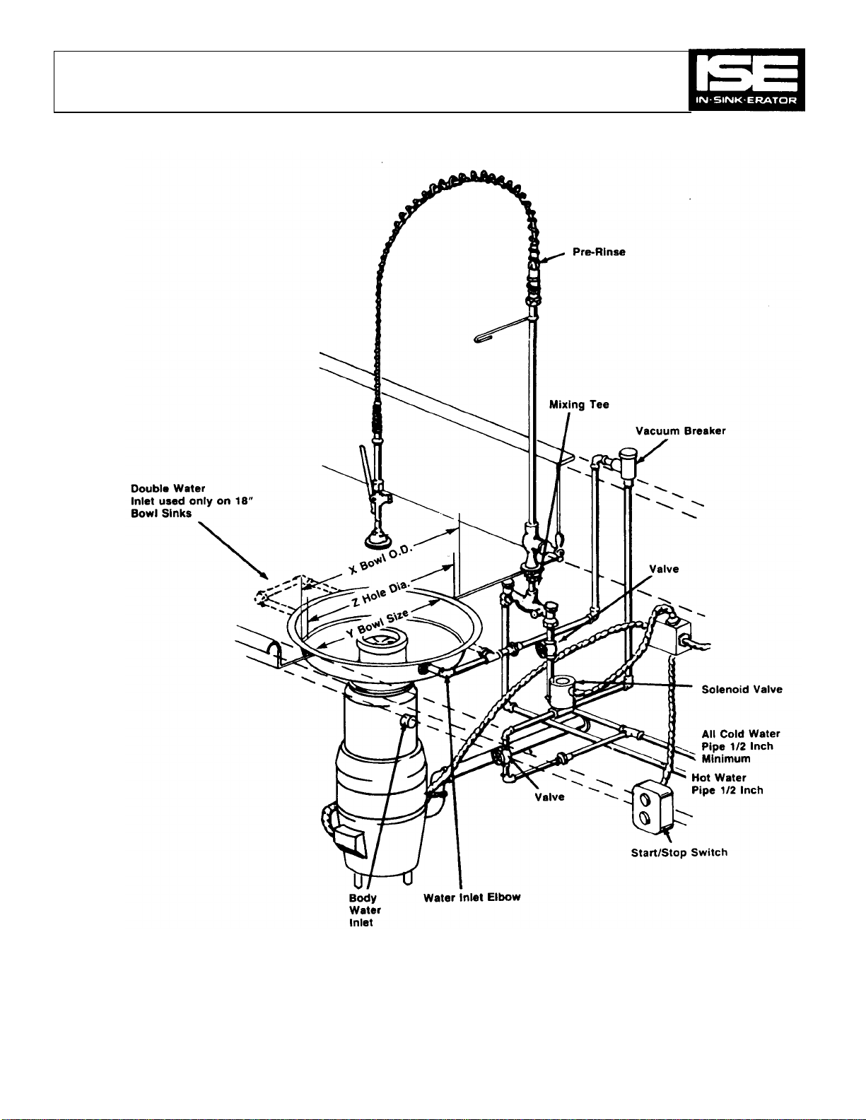
all H.P. The top of the swirling water
et. Too much water
can overload motor and reduce grinding efficiency. Water volume
can be controlled by a properly rated flow control valve or a hand
At no time should hot water be connected directly to disposer or
se assembly is installed, tempered hot water is
over bottom flange of
bottom
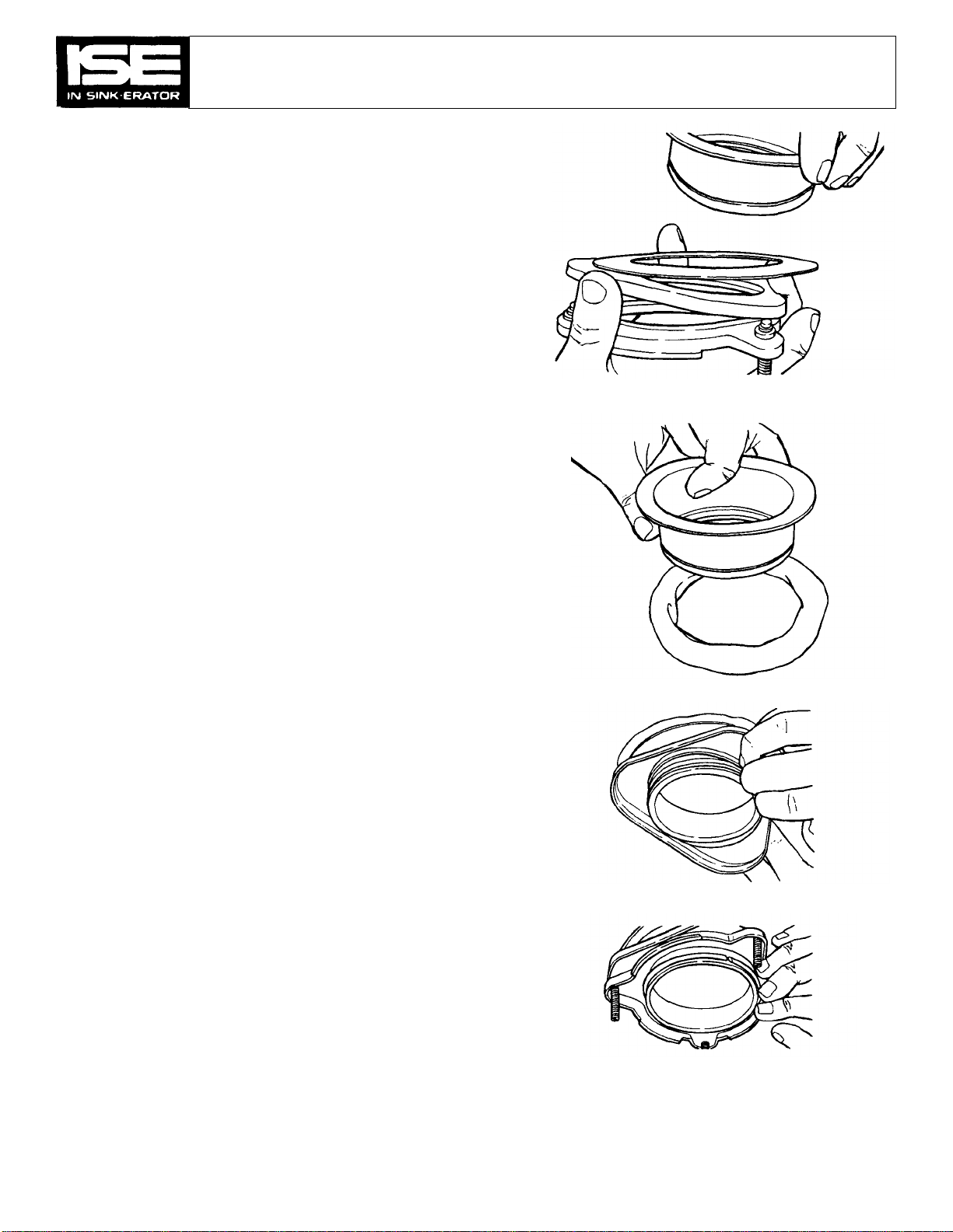
Position mounting flange down over outside of mounting gasket.
Threaded fasteners in mounting flange will fit into recesses in top
capscrews from bottom of mounting gasket into
any two opposite threaded fasteners in the mounting flange (see
d mounting gasket together at
capscrew location while assembling capscrews. Make about three
SECTION 5
8. Water volume adjustment —
should occasionally crest to the body water inl
operated valve.
9.
bowl sink. If pre-rin
acceptable.
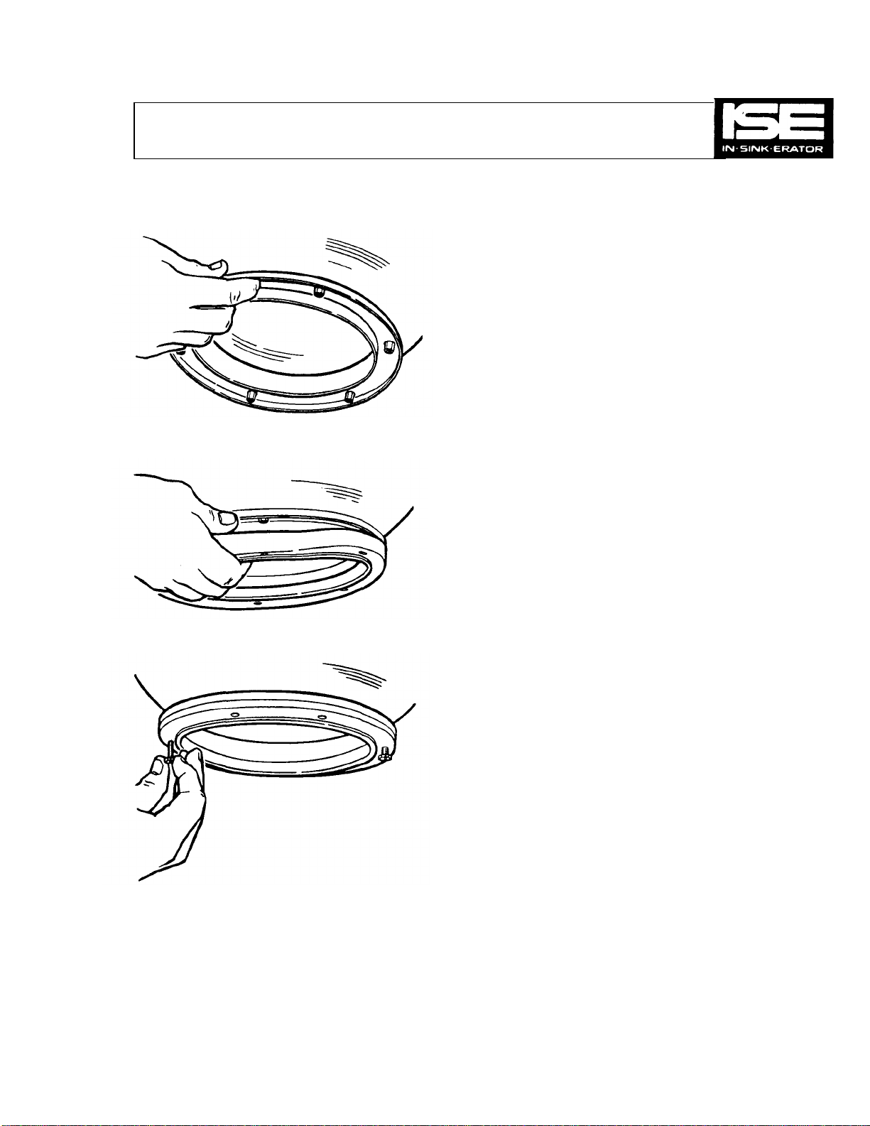
Figure 5-1.
INSTALLATION OF DISPOSER BASE UNIT
TO SINK BOWL OR COLLAR ADAPTOR
1. Slip the mounting flange (see Figure 5-1)
bowl sink or collar adaptor, and then fit mounting gasket to
flange (see Figure 5-2). Top side is marked on mounting gasket.
NOTE
Figure 5-2.
Mounting flange, mounting gasket and capscrews are packed and
shipped with each bowl sink or collar adaptor.
2.
(
of mounting gasket.)
3. Assemble two (2)
Figure 5-3.
6
Figure 5-3). Hold mounting flange an
full turns.
Page 8
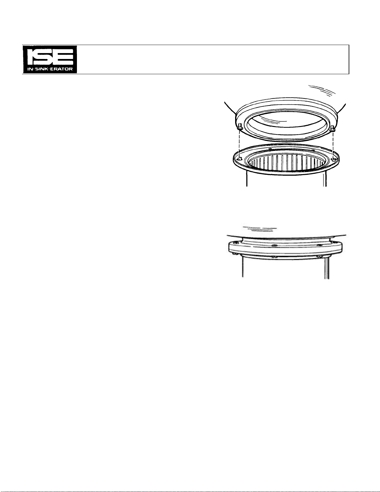
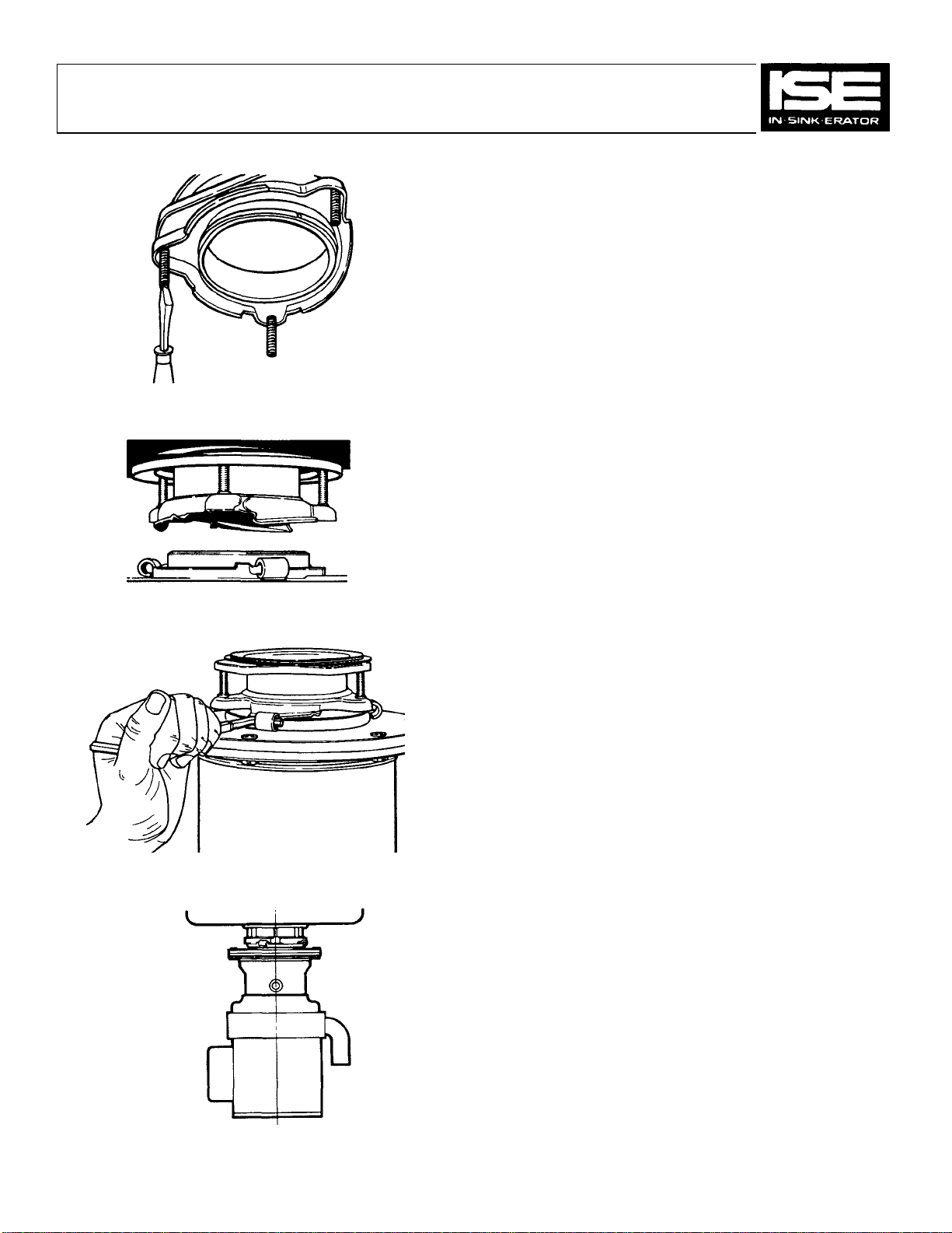
sink nozzle(s). When disposer is fitted to a bowl sink, it is not necessary
See Step8, General
Figure
5-4. Figure
5-5.
SECTION 5
4. Raise disposer and engage capscrew heads in keyhole slots in
disposer body flange and turn disposer (see Figure 5-4). The
disposer will now hang by itself. Assemble four remaining
capscrews but do not tighten (see Figure 5-5).
For 3 H.P. through 10 H.R, unit is floor supported.
5. Turn disposer into position, line up the plumbing connections and
tighten the capscrews in disposer mounting. Capscrews are to be
tightened until edges of mounting flanges come together.
6. Make plumbing and electrical connections to the disposer per local
codes.
7. DISPOSER MOUNTED TO BOWL SINK: Connect cold water to bowl
to connect disposer body water inlet (see Figure 5-6).
Plumbing Instructions, for recommended cold water requirements.
8. DISPOSER MOUNTED TO COLLAR ADAPTOR: Connect cold water
to body water inlet. See Step 8, General Plumbing Instructions, for
recommended cold water requirements.
9. In connecting an IN-SINK-ERATOR to a septic tank, consult codes for
required size of tank and for the proper seeding (starting) of tank for
trouble-free installation.
Removal
1. Removal is the reverse of installation.
7
Page 9
SECTION 5
Figure 5-6.
8
Page 10
NOTE
For special mounting adaptor installation, refer to instructions packed
with adaptor.
INSTALLATION OF DISPOSER BASE UNIT TO No. 5 SINK
FLANGE MOUNTING (Standard 3-1/2" — 4" Sink Opening)
1. Unscrew the 3 mounting screws on the sink flange mounting
assembly until flush with mounting ring surface. Pry out the snap
ring holding the sink sleeve and separate all parts (see Figure 5-7).
2. To install stainless steel sink flange, form a ring of top grade oil
base putty around sink opening. Use putty that always remains
pliable. Insert sink flange into sink opening (see Figure 5-8).
3. From underneath sink, place fibre gasket over sink flange, up
against bottom of sink. Follow fibre gasket with steel back up ring,
flat side up (see Figure 5-9). Follow with upper mounting ring
having three set screws flush with top of mounting ring. Place these
parts above groove in sink flange and insert spring steel snap-lock
ring into groove (see Figure 5-10).
SECTION 5
Figure 5-7.
Figure 5-8.
Figure 5-9.
Figure 5-10.
9
Page 11
With a screwdriver tighten the three mounting screws evenly until
fibre gasket and back up ring draw up snugly against underside of
bolts provided.
for sequence of assembling parts to top of
lower mounting
(having lugs) is positioned with lugs located to right of back up
When mounting rings are positioned, hold unit up and turn lower
upported.
Insert service wrench in lug from left side and continue to turn
quarter turn)
until the two mounting lugs meet and snap into position (see
that will permit proper alignment for
degrees for easy
Make cold water connection to disposer body water inlet (see
General Plumbing Instructions, for
SECTION 5
Figure 5-11.
4.
sink. Sink flange will now be securely in place (see Figure 5-11).
5. Attach adaptor flange to top of disposer with six (6)
See Figures 5-1 to 5-5
disposer.
6. Raise disposer to sink mounting assembly so that
screws on upper mounting ring. See Figure 5-12.
7.
mounting assembly to right (clockwise) until unit is self s
lower mounting assembly to right (approximately one-
Figure 5-12.
Figure 5-13.
Figures 5-13 and 5-14).
8. Swivel unit to a position
installation of a trap. Unit can be turned 360
installation.
9.
Figure 5-6). See Step 8,
recommended cold water requirements).
REMOVAL
1. Removal is the reverse of installation.
Figure 5-14.
10
Page 12
SECTION 5
fl
oor clearance is not sufficient.
Disposer motor phase, single or three phase, must be the same as power
as
overload protection. Therefore, any starting switches furnished that have
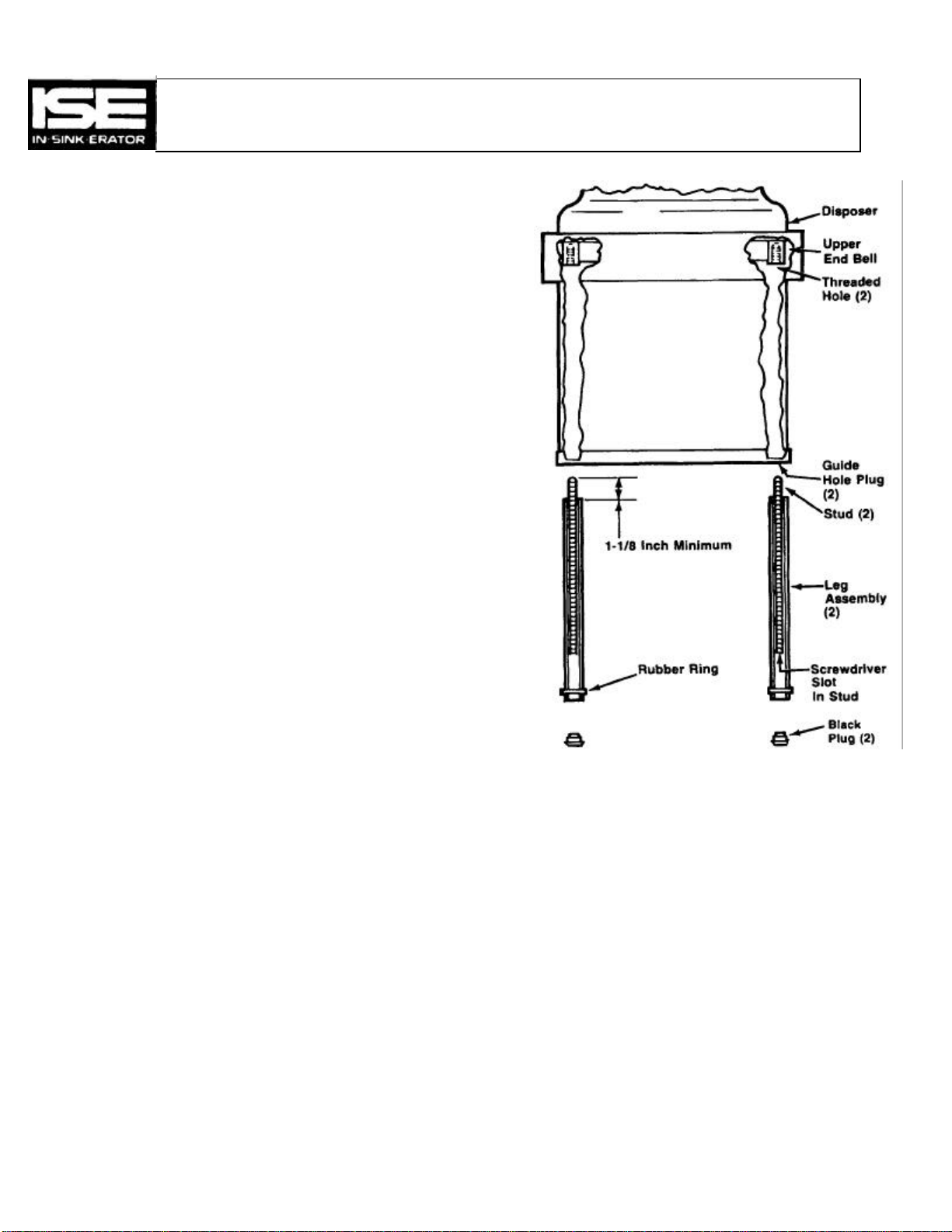
Figure
5-15.
DISPOSER LEG INSTALLATION — See Figure 5-15.
1. Pry the two guide hole plugs from the bottom of the disposer.
2. Place the leg assemblies in the guide holes at the bottom of disposer.
Screw the threaded studs into the threaded holes in the upper end bell and
tighten with screwdriver. It will be necessary to demount the disposer if
3. Push the black plug into the bottom of leg tube and adjust to proper
length.
4. Push the rubber ring on each leg up securely against the bottom of the
disposer to maintain leg adjustment.
GENERAL ELECTRICAL INFORMATION
Disposers shipped from the factory are NOT connected for a specific
voltage. Please refer to the STANDARD MOTOR CONNECTION
WIRING DIAGRAMS in the disposer terminal box for correct voltage
connections.
The standard disposer voltages are 115/208/230 volts for single phase
electrical power and 208/230/460 volts for three phase electrical power.
NOTE
source and line phase. Disposer wiring connection voltage must be the ie
the voltage of the line or power supply.
CAUTION
ALL ELECTRICAL CONNECTIONS SHOULD BE MADE TO
CONFORM TO LOCAL CODES. BE CERTAIN THAT ALL
IN-SINK-ERATOR DISPOSERS ARE CAREFULLY AND
PERMANENTLY GROUNDED.
The motor connection wiring diagrams for the 1/2 through 10 H.P. models
are found inside of the disposer terminal box at the front of the disposer.
NOTE
All IN-SINK-ERATOR disposers are equipped with built-in thermal
provisions for heaters will not be supplied with heaters.
11
Page 13

SECTION 5
ELECTRICAL INSTALLATION 1/2 Through 10 H.P.
The following simple steps are required to complete the electrical
connections to the IN-SINK-ERATOR Disposer.
1.
2. Pull the terminal box out of the stainless steel trim shell.
3.
4. Connect the grounding wire to the ground screw.
5. Connect incoming wires to motor lead wires.
Be certain that the wiring connections are the same as those on the Motor
Control Wiring Diagram for your group of controls (see Section 16).
6.
BE CAREFUL NOT TO PINCH WIRES WHEN REPLACING THE
TEERMINAL BOX.
Complete Electrical Information Located Inside Disposer Terminal Box.
Remove the screw at the center of the terminal box in front of the
disposer.
Assemble an electrical conduit connector to the hole in the extension plate at the bottom of the exposed wiring compartment.
NOTE
Replace terminal box in position in the trim shell.
CAUTION
NOTE
12
TESTING — ALL MODELS
1. Check to be sure disposer is free of all objects.
2. Turn on disposer and determine that cutting elements revolve and
that water flows automatically.
3. Test mounting assembly and plumbing connections for leaks.
4. If disposer fails to operate: (A) Check wiring connections. (B)
Determine if built-in thermal overload protector has tripped —
reset by hand only. Refer to operator's instruction sheet.
CAUTION
IF DISPOSER STOPS, DO NOT LOOK FOR CAUSE UNTIL
STARTING NTROL IS TURNED "OFF".
NOTE
No lubrication is necessary as all bearings are permanently lubricated.
Page 14
5.
SECTION 5
OPERATING INSTRUCTIONS
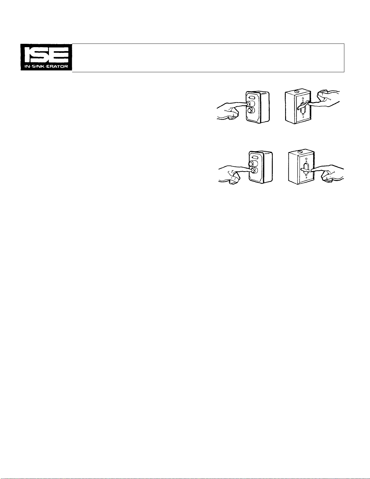
1. PUSH THE START BUTTON on the switch to put the disposer in
operation (see Figure 5-16). Before you start feeding food waste into
the disposer, make sure that a steady stream of water is flowing into
the disposer.
2.
Don't feed garbage into disposer until unit is started and water
running.
3. FEED THE GARBAGE into the disposer in a steady, continuous flow.
4. Don't overload disposer with excess amounts of garbage and water.
The unit will consume food waste faster when you feed it steadily.
Figure 5-16.
Recommended cold water requirements.
IMPORTANT
1/2 through 1-1/4 H.P 5 GPM
1-1/2 through 2 H.P. 8 GPM
3 through 10 H.P. 10 GPM
Don't touch the water valve after the correct flow of water is achieved
by adjusting plumbing valves. Grinding efficiency will be decreased if
the water swirl is more than one half way up the disposer body.
6. Don't put your hands into disposer while it is in operation.
7. Don't stop disposer with garbage in it, let it run for approximately
three minutes to clear itself of all ground garbage. This will help maintain a clean and odor-free unit and avoid drainline stoppage.
8. Do not operate without factory recommended safety guards.
9. Push the STOP BUTTON on the switch to stop the disposer's operation (see Figure 5-17).
10. To prevent accidents, make sure the disposer is shut off before you
leave it.
Figure 5-17.
13
Page 15
SECTION 5
Overloading or the presence of a foreign object (metal) can cause
Jammed
IF THE DISPOSER STOPS, ALWAYS TURN THE STARTING
THE "OFF" POSITION BEFORE LOOKING
which may have tripped and stopped electrical current to the motor
Figure 5-18.
DISPOSER JAM
1.
the disposer to jam and must be cleared (see section 15,
Disposer).
CAUTION
CONTROL TO
FOR THE CAUSE OF THE DISPOSER STOPPAGE.
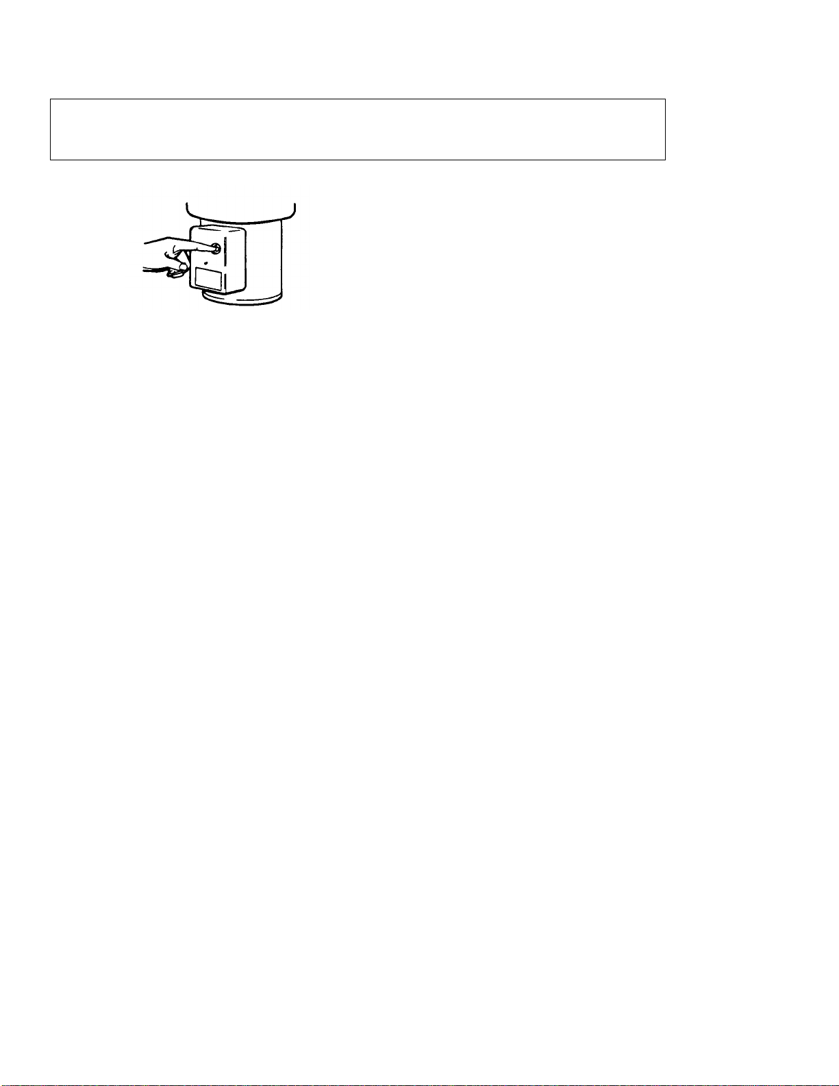
2. Once the jammed condition is cleared, locate the red reset button
which can be found in the lower front of the disposer (see Figure 5-
18). This is a sensitive electrical control (overload safety switch)
to prevent motor burn-out. WAIT 3 to 5 minutes to allow motor to
cool down. Then press the red button hard, possibly with two
thumbs, to reset the safety switch.
NEVER strike the red button with an object.
14
Page 16

water runs O.K.
Starting switch on sink inoperative.
PROBLEM-CAUSE-SOLUTION
PROBLEM POSSIBLE CAUSE SOLUTION
Unit will not start —
Motor dead —
no sound —
Overload protector tripped, open.
Overload protector burned out, open
circuit.
Stator burned out, open.
Reset overload protector, allow 5 minutes cool down, then press red
button hard using both thumbs.
Test and replace overload protector.
Test and replace stator, also inspect for pinched (grounded/shorted)
motor lead wires.
Section 6
Will not start —
Motor dead —
water does not run.
Motor hums —
Water runs ok —
disposer will not run.
Jammed grind elements.
Water in motor.
No Electric power to disposer.
No electrical power.
Jammed grind elements.
Start switch in motor (single phase units).
Motor parts binding.
Clear jam and reset overload protector, (see Section 15, Jammed
Disposer Conditions).
See "Water in motor".
Check terminal box motor connections for power with volt meter.
Inspect for unconnected wires.
Check for blown fuses or tripped circuit breaker in main electrical
supply panel.
Power supply not connected to starting switch on sink.
Remove cover from switch and check operation.
Clear jam — (see Section 15, Jammed Disposer Conditions).
Switch contacts not making contact or burned off. Replace start
switch.
Motor thru bolts loose — tighten. Lower end bell misaligned —
remove and reassemble.
15
Rotor drag.
Start windings (on single phase units) open.
Capacitor (single phase units only).
Voltage.
Improper wiring at motor and/or starting switch or
solenoid valve.
Rotor shaft pulling into and binding against stator core. Check I.D. of
stator core and O.D. or rotor shaft core for score marks. Check for
worn bearings and replace If necessary.
Check and replace if needed.
Weak — test — (see Section 14, Capacitor Testing), replace if
necessary.
Low or improper voltage to disposer. Check power supply at
disposer.
Using correct wiring diagram, check, trace and make proper wiring
connections.
Page 17

Centrifugal actuator on motor shaft (single
SECTION 6
PROBLEM POSSIBLE CAUSE SOLUTION
Motor hums — water
runs ok — disposer will
not run. (Continued)
Motor starts — runs then
trips overload protector.
Single phasing (three phase units only). One or two windings open. Check stator windings, replace if
open. Also check for shorts and grounds.
Inspect, adjust, replace centrifugal actuator if necessary.
phase units only) stuck or loose spring.
Doesn't allow motor switch to open.
Motor switch contacts (single phase units
only) welded/burned closed.
Stator windings shorted. Test stator for circuitry using proper motor winding
Water in motor Inspect motor parts. Also lower bearing area of
Improper use of disposer. Potential jam — (see Section 15, Jammed Disposer
Voltage Marginal (low) power supply. Unbalanced power supply
Wiring connection improper. Make proper connection per wiring diagram.
Overloaded electrical power supply line. Connect to another circuit. Disposer motor should be
Overload protector. May be weak, improperly connected or wrong overload.
Replace motor switch.
diagrams.
upper end bell for leaking water. Repair with new
bearing/seal kit. Replace other parts if necessary.
See "Water in motor".
Conditions), operator overloading unit — explain correct
use.
(three phase only). Cannot be corrected by service
technician.
connected to its own separate circuit.
Test O.D. Check for correct connections using wiring
diagram arid parts sheet.
Runs slow and stops when
food waste is put in
disposer.
Heater Coils. Incorrectly rated heater coils in magnetic starter. To be
Voltage connections Low voltage power supply with high voltage
16
corrected or bypassed by electrician.
motor connections.
Reconnect motor lead connections using wiring
diagram.
Page 18

SECTION 6
PROBLEM POSSIBLE CAUSE SOLUTION
Trips overload protector,
circuit breaker or blows
fuses immediately on
starting disposer.
Stator Direct short in motor windings — test with ohmmeter.
Motor lead connections Check and correct connections. Also check for bare motor lead
wires. Insulate where required.
Disposer motor runs ok,
but little or no water.
Starting Control (Switch) Improperly wired — check and correct.
Improper Voltage Check disposer electrical specifications, power supply and
motor lead connections.
Improper fuse or circuit breaker Check — corrections to be made by electrician.
Overload protector Weak or incorrect part — replace.
Water supply valve shut off. Open water valve in water supply line and adjust for
correct/recommended G.P.M.
Water solenoid valve malfunction. Check solenoid —
• Coil weak, marginal voltage or wiring for low voltage.
Low water pressure. Must be increased — responsibility of equipment owner.
• Bleeder hole in diaphragm out of position. Disassemble,
reposition and reassemble.
Dirty — Disassemble valve, clean thoroughly and reassemble
Coil — Burned out (open) — replace valve. No electric power
to valve coil — trace circuit for cause.
Water in motor Seals in bearing/seal area worn. Replace parts using new bearing and seal kit.
Time delay relay. Improperly installed or defective "load" circuit. Check for
proper connections and "load" with volt meter.
Upper end bell. Cracked or eroded — replace upper end bell.
See "Water leaks at grind chamber area".
Cleaning abuse. Kitchen cleaning crew used water hose for cleanup and "hosed
down" the disposer, driving water into the motor.
17
Page 19

id drain connections and use of disposer
SECTION 6
PROBLEM POSSIBLE CAUSE SOLUTION
Noisy Worn Bearings. Replace bearings.
Vibrates excessively. Excessive water entering disposer.
Rotor core on motor shaft. Rotor core slips — not tight on shaft. Replace motor shaft.
Disposer Remove unit from sink and trap. Rest unit on floor, hold
Installation The quality of material, design and installation of the sink,
Overloading disposer with hard food
waste or non-biodegradable material.
securely and run. If unit is at fault, it can now be corrected.
drain line, adjacent walls, fasteners, etc. may be less than
described for disposer operation.
Securing the table, sol
legs may help dampen any magnified grinding noise.
Adjust water flow to disposer. See Section 5 for
recommended G.P.M. If unit is installed in a pot sink with
number 5 mounting assembly, drain water from sink before
turning on disposer.
Do not overload disposer with excessive amounts of
hard food waste (bones). Do not grind nonbiodegradable material.
Leaks Water.
IMPORTANT NOTE
REVIEW BEFORE DIAGNOSING ANY LEAKING CONDITION.
Leaks from one area may be seen at a totally different area of the disposer.
EXAMPLE: The water from a leaking mounting assembly or from a cracked stationary shredder can run down the outside of the
disposer and drip from the bottom of the unit giving an impression of "water leaking from the motor".
Whenever diagnosing any leaking problem, review all possibilities listed before making conclusions or repairs.
Water leaks at mounting Loose mounting screws. Tighten all mounting screws. Tighten locking ring if
or waste discharge. mount is a number 5 mounting assembly.
Pinched or broken gasket. Replace gasket.
Water in the motor. See "Water in motor".
18
Page 20

ean out drain lines from disposer to main sewer. Vent lines
minute post
SECTION 6
PROBLEM POSSIBLE CAUSE SOLUTION
Water leaks at grind
chamber area or center of
unit.
Stationary shredder gasket pinched,
misfitted or broken.
Replace gasket.
Syphon breaker leaks. Loose plumbing connections. Tighten plumbing connections.
Water inlet connection loose in body. Replace with new body, or totally remove inlet connector
from body and use plumbing fittings (nipple, el, nuts, rubber
gaskets) to repair.
Lower body cover. Tighten bolts holding lower body cover to upper end bell
(compress stationary shredder gasket). If this fails to secure
the leak, the "rivnuts" in the lower body cover have
separated enough, not allowing compression of the gasket.
Replace lower body cover.
Stationary shredder. Cracked or broken, allows water leaks to the outside of the
unit and runs down the outside of the motor. Replace
stationary shredder.
Installed improperly. Syphon breakers must be installed 6 inches above the "flood
plane" which is the top working surface of the sink —
reinstall.
Plumbing connections backwards — reinstall.
"Poppet" in syphon breaker worn, cracked or missing —
replace with new syphon breaker.
"Poppet" in syphon breaker sticking — disassemble, clean
and reassemble.
Does not drain or drains
slowly. Water in disposer
after being shut off
(possibly some food
waste also).
or
Frequent drain line
blockage.
19
Drain line blockage.
Center line of disposer waste outlet is
below center line of drain line.
Improper drain line slope. Horizontal drain line require minimum of 1/4" fall per foot.
Grind elements. Worn or piece broken away — allows large chunks to enter
Cl
may also require cleaning. Instruct user to use 3
flush. Possibly install a time delay relay.
Check for proper water flow — could be too little water
being used.
Plumbing adjustment required to drain line.
drain line. Replace grind element(s).
Page 21

Discontinue this practice. Food waste disposers are designed
lties when introduced
SECTION 6
PROBLEM POSSIBLE CAUSE SOLUTION
disposer during
operation.
Splashing from bowl. Spray nozzles not installed properly. Spray nozzles should be "pointed" downward approximately
Excessive water entering disposer and/or
excessive water pressure.
Adjust water entering unit to proper recommended G.P.M. Splashing — from
If water pressure cannot be adjusted, install a safety baffle,
silver guard and/or cover.
15 to 20 degrees.
Water runs continuously
after disposer is turned
off.
Excessive wear on
grinding elements.
Solenoid valve.
Normal. Normal if a time delay relay is being used. Water may run a
Time Delay Relay. Time delay may be defective and not shutting down. Initiate
Disposer undersized. Reduce use. Replace disposer with proper size.
Highly abrasive material being ground in
abundance.
Non-biodegradable material being ground.
Installed backwards — arrow on solenoid valve must point
down stream.
Valve not closing — dirty — disassemble and clean.
Bleeder hole in diaphragm out of position. Disassemble and
reset diaphragm.
High water pressure — pressure must be reduced.
few seconds to 10 minutes depending on time delay setting.
Used for post flush.
circuit always active and not shutting down. Check circuitry
with volt meter.
Do not grind abrasive material such as glass, crockery,
ceramic or clam shells.
to grind food waste. Other materials should be considered
trash and cause waste treatment difficu
into drain lines.
Will not grind.
Excessive water entering disposer. Adjust water supply to proper recommended G.P.M.
Insufficient grinding time. Do not turn off unit until all food waste has been ground
Worn grinding elements. Replace cutting elements or reverse direction of motor if
Plugged teeth in stationary shredder. See Section 15, Jammed Disposer Conditions.
20
away with a 3 minute flush.
reversing controls are not used. (Three phase — "flip flop"
any two of the three power leads at the motor.) (Single phase
— "flip flop" wires Number 2 and 5 in the disposer motor
terminal box.)
Page 22

seal
nent sleeve
Make certain the sleeve is fully down to the snap ring by driving
ing and seal
Identify all controls used on the installation. Review appropriate
PROBLEM POSSIBLE CAUSE SOLUTION
New bearings and seal kit
binds rotor shredder when
assembled.
Disposer hums but does
not start.
or
Loose after assembly.
Misassembled.
Disassemble bearing/seal kit. Can be reused, but new lower
is required.
Reread bearing/seal kit instructions and follow closely. Use all
parts in the kit. Make absolutely certain the upper end bell
bearing cavity is totally free of grit, dirt, score marks, burrs and
grease. Also the permanent snap ring in the I.D. of the bearing
cavity.
Some motor shafts (lower horsepower) have a perma
pressed on that surrounds a snap ring on the shaft. The lower
seal rides on the sleeve which also acts as a thrust spacer. The
sleeve must be firmly against the snap ring.
it with a brass rod and hammer or with an arbor press.
SECTION 6
Disposer runs O.K. only
when using "cheater" cord
and bypassing all controls.
Disposer and/or electrical
controls are wrong for the
available power supply.
Reassemble per instructions.
Check to make certain you are using the correct bear
kit for the disposer model and any other new parts.
Controls
wiring/electrical diagrams. Inspect controls visually and with
Ohm and/or Volt Meters.
Ordered wrong or sent in error. Explain to manager and suggest contacting his supplier.
21
Page 23

DISPOSER SIZING CHART
Up to
100 SS-75 SS-50 ------
------
--------
SECTION 6
Hotels Restaurants Hospitals Cafeterias Commissaries
Persons Soiled
Per Meal Dish Table
Vegetable Salad Pot Meat
Prep.Area Prep.Area Sink Prep.Area
100-150 SS-100 SS-75 SS-50 SS-50 -------150-175 SS-85 SS-100 SS-75 SS-50 SS-150
175-200 SS-150 SS-150 SS-75 SS-75 SS-150
200-300 SS-200 SS-150 SS-75 SS-75 SS-300
300-750 SS-300 SS-150 SS-75 SS-75 SS-300
750-1500 SS-500 SS-300 SS-150 SS-150 SS-500
1500-2500 (2) SS-500 SS-300 SS-150 SS-150 SS-500
2500-over Contact your Food Service Consultant or In-Sink-Erator
FOR SPECIAL APPLICATIONS, SUCH AS SUPERMARKETS OR OTHER HEAVY, CONTINUOUS
VOLUME INSTALLATIONS, SELECT MODELS SS-750 OR SS-1000
Additional IN-SINK-ERATOR units or a disposer larger than indicated in the chart may be necessary in the following
instances: if large amounts of fibrous, hard or bulky materials are in the mixed wastes, if there is an occasional need for
increased capacity, due to special occasions, or if waste volume is expected to grow.
22
Page 24

TERMINAL BOX AND TRIM SHELL SECTION 7
lear
REMOVAL
1. Place unit on bench upside down.
2. Remove terminal box retaining screw (see Figure 7-1).
3. Remove terminal box (see Figure 7-2).
4. Remove two trim shell retaining screws (see Figure 7-3).
5. Turn unit so waste outlet is facing away from you.
6. Grasp trim shell with both hands. Spread shell wide enough to
allow it to clear bottom cover. Angle upper edge of shell towards
yourself so opening in shell will pass over terminal connection
area (see Figure 7-4). Continue to lift shell and angle it towards
yourself until shell is in a horizontal position. Remove the trim
shell.
ASSEMBLY
1. Place unit on bench upside down with waste outlet facing away
from you.
2. Grasp trim shell with both hands, holding trim shell in a
horizontal position. Insert leading lower edge of trim shell in
space between terminal connection and upper shroud. Raise shell
to a vertical position, at the same time spreading it so it will c
the bottom cover.
NOTE
Use care so as not to damage lead wires in terminal box area.
3. Install two trim shell retaining screws.
4. Assemble terminal box cover to unit.
5. Install terminal box retaining screw.
Figure 7.1.
Figure 7.2.
Figure 7-3.
6. Place unit on bench in upright position.
Figure 7-4.
23
Page 25

2.
stationary shredder. With terminal box facing you, the water inlet
SECTION 8
Figure 8-1.
BODY AND COVER
REMOVAL
1. Disassemble as outlined in Section 7.
2. Using a socket wrench and a long extension or a long
screwdriver, reach up under the cover and remove the slotted
head capscrews securing the body and cover to the end bell (see
Figure 8-1).
3. Lift the body and cover assembly off of the unit.
INSPECTION AND ASSEMBLY
1. Inspect body shredder seal. If damaged or deteriorated, replace it.
Place unit on bench in upright position.
3. Position body and cover assembly on motor assembly, making
sure locating tabs are lined up with the locating grooves in the
boss should be to your right.
4. Place capscrew in socket wrench. Insert wrench up under cover
and guide cap-screw to capscrew hole. Thread capscrew about
one-half way in. Follow same procedure with remaining
capscrews until all are partially threaded. At this point you can
complete the threading and tightening process.
5. Reassemble according to Section 7.
24
Page 26

BOTTOM COVER AND FAN SECTION 9
Remove three motor thru bolts retaining bottom cover (see Figure
lifted off.
With a rawhide or plastic mallet, tap on the fan hub until the end of
Bottom cover wilt only fit one way. Be sure to align motor thru bolt
es in bottom cover with motor thru bolt holes in lower end belt,
and align leg access holes in bottom cover with threaded recess in
or thru bolts between bottom
cover and motor thru bolt hole in lower end belt. After this is done,
Figure
9-1. Figure
9-2.
REMOVAL
1. Disassemble according to Section 7.
2.
9-1). Between bottom cover and lower end bell are three spacer
tubes (see Figure 9-2). Retain these as they must be used for
reassembly. After thru bolts are removed, bottom cover can be
3. Remove snap ring from motor shaft to remove jam.
4. Using two wide, flat screwdrivers, place one on each side of the
shaft under the fan. Pry up on fan until it moves up on shaft
approximately 1/8" (see Figure 9-3).
5. Lift up and off.
INSPECTION AND ASSEMBLY
1. Inspect fan bore prior to reassembly. A locking rib should be
evident in fan bore. If it is not, the fan should be replaced.
2. Place fan on shaft, being sure that flat surfaces of fan bore line up
with flat surfaces on shaft.
3.
the shaft and fan hub are even. Then place one thumb on each side
of the fan hub and press down firmly. The locking rib in the fan
bore will seat itself in the locking groove on the shaft.
4. Install snap ring.
5. Place bottom cover on unit.
NOTE
hol
end belt.
6. After bottom cover is aligned, motor thru bolts can be inserted.
NOTE
Be sure spacer tubes are placed on mot
thru bolts can be threaded into upper end bell.
7. Reassemble according to Section 7.
25
Figure 9-3.
Page 27

Scribe mark the stationary shredder and the upper end bell (see
(or a "crow
A puller that works very well for removing the stationary grind ring
can be fabricated from the measurements shown on the diagram in
shredder with a ball peen or steel
SECTION 10
STATIONARY SHREDDER
REMOVAL FROM UNIT
1. Disassemble as per Section 7 and Section 8.
IMPORTANT
Figure 10-1).
2. Place a short section of pipe (approximately 1-1/4" long) over the
rotor shredder mounting nut. This center piece is to be used as a
fulcrum point. Place the flat end of service tool #6462
bar") under the protruding edges located in the wall of the
stationary grind ring. Rest the #6462 tool on the center fulcrum
point.
NOTE
Figure 10-1.
Figure 10-2.
Figure 10-2. This tool is not available from ISE.
Insert the "L" shaped lip of the shredder puller into the groove
beneath the rectangular grinding elements. Use an Alien wrench to
turn the threaded rod clockwise. As the threaded rod is turned down
against the outer shoulder on the upper end bell, the stationary
shredder will be pulled free of the upper end bell.
3. A mallet is now used to strike downward on tool #6462 (see Figure
10-3). Two or three sharp blows will raise the grind ring up and out
of position.
NOTE
Never strike the grind ring or rotor
hammer. Either babbitt, nylon, leather or wood mallets must be used.
Figure 10-3.
26
Page 28

Proper alignment of the scribe marks is important, as the upper body
grooves in the shredder do not line up with the locating tabs on the
INSPECTION AND ASSEMBLY
Prior to reinstalling the stationary shredder, we suggest that it be
carefully inspected. If cracked, chipped, or broken, or if excessive
wear is evident, then stationary shredder should be replaced.
To assure a trouble-free installation, the bottom surface of the
stationary shredder and the stationary shredder recess in the end bell
must be cleaned of all old mastic and dirt, so as to allow the
stationary shredder to fit squarely in the upper end frame.
See Figure 10-4.
1. Apply a coating of water resistant silicone sealant across the
bottom of the stationary shredder to form a seal with the upper
end bell.
2. Position the stationary shredder in the upper end bell, being sure
the scribe marks are aligned.
NOTE
SECTION 10
Figure 10-4
will not fit over the stationary shredder when assembling if the
body.
3. Strike fairly hard alternately on the upper rim of the stationary
shredder until it is seated fully in the upper end bell (see Figure
10-5).
NOTE
Never strike the stationary shredder with a steel hammer. Either
babbitt, nylon, leather or wood mallets must be used.
Reassemble according to Section 7 and Section 8.
Figure 10-5.
27
Page 29

SECTION 11
Place a pry tool under one edge of the rotor shredder and a similar
tool under the opposite edge of the rotor shredder. Work the tools
Prior to reassembly, the rotor shredder should be carefully inspected
rizontal bars on the top surface
of the shredder show signs of excessive wear or are broken, the rotor
Figure
11-1.
ROTOR SHREDDER
REMOVAL
1. Disassemble as per Section 7, 8 and 10.
2. Hold the rotor shredder with a vise-grip or a channel lock pliers so
it will not turn. With a socket wrench or box end wrench, remove
the mounting nut, steel washer and fibre gasket (see Figure 11-1).
NOTE
Mounting nut has right hand threads.
3.
alternately until rotor shredder is pried off of the keys which
position the shredder on the shaft (see Figure 11-2).
INSPECTION AND INSTALLATION
to determine if it is reusable. If the ho
shredder should be replaced.
1. Place rotor shredder on shaft and align keyways in shredder with
keys on shaft. After keys are lined up, tap shredder down until it is
fully seated.
2. Install new fibre gasket, steel washer and self locking hex
mounting nut.
3. Hold rotor shredder with vise-grip or channel lock pliers so it will
not turn. With a socket or box end wrench, tighten mounting nut
firmly. Then reassemble as per Section 7, Section 8 and Section
10.
Figure 11-2.
Page 30

UPPER AND LOWER END BELL
REMOVAL FROM UNIT
1. Disassemble as outlined in Sections 7, 8, 10 and 11.
TRI-LIP SEAL REMOVAL
Review Figures 12-1 and 12-15 before proceeding.
1. Remove the two exposed woodruff keys (13) and slide the shield
(1) up and free from the shaft (15) (see Figure 12-1).
2. Pull the sleeve (4) up and off the shaft.
3. Remove six (or twelve depending on size of disposer) screws (2)
allowing the tri-lip seal (3) to be pulled free from the upper end
bell (10). Remove the third woodruff key (14) from the shaft.
4. The "0" Ring (5) and the centrifugal moisture shield (6) can now
be pulled up and free from the shaft. The bearing area is now
exposed.
SECTION 12
5. Scribe mark upper end bell and stator and lower end bell and
stator (see Figure 12-2).
6. Using the stationary shredder as a "stand", stand unit upside down
and remove bottom cover and fan as outlined in Section 5. The
upper bearing will probably slide off the shaft onto the work
Figure 12-1.
1. Shield 8. Bearing Cone and Cup
2. Screw 9. Bearing Spacer
3. Lip Seal 10. End Bell
4. Sleeve 11. Thrust Washer
5. 0-Ring 12. Oil and Water Retainer
Centrifugal Moisture
6.
Shield
7. Bearing Cone and Cup
13. Woodruff Key (2)
14. Woodruff Key
15.
Rotor and Shaft Assembly
Figure 12-2.
29
Page 31

SECTION 12
Figure
12-3.
7.
Lay unit on its side and tap upper end bell alternately on opposite
sides with a nylon or rawhide mallet until upper end bell is
disengaged (see Figure 12-3).
8.
Turn unit right side up using the stationary shredder as a stand.
9.
Pull upper end bell (10) out and free of rotor and shaft (15).
CAUTION
THE MOTOR SHAFT MIGHT PULL AWAY WITH THE
UPPER END BELL. DO NOT ALLOW IT TO DROP.
REMOVAL OF BEARINGS AND OIL AND WATER
RETAINER
1.
Remove the upper tapered roller bearing, (see Figure 12-4) and
the cone spacer (see Figure 12-5). If they are to be reused, we
suggest they be wrapped in a clean rag or paper to prevent
contamination by dirt or dust. If they are not to be reused, discard
them. Place end bell on bench upside down.
2.
Use a pry bar to remove the oil and water retainer (see Figure 12-
6). Discard old seal.
Figure 12-4.
Figure 12-5.
Figure 12-8.
30
Page 32

them, proceed as follows: Lay end bell upside
Do nor attempt to remove the large snap ring installed in the center of
SECTION 12
NOTE
SS-300 AND SS-500 OVER SERIAL NO. 70,000 AND MODEL
SS-750 AND SS-1000 UNITS ONLY: Located between the oil and
water retainer and the lower tapered roller bearing is a steel thrust
washer. Remove and retain this, as it must be reinstalled at time of
reassembly (see Figure 12-7).
3. Remove lower tapered roller bearing. If it is to be reused, place
with upper bearing. If not to be reused, discard it (see Figure 12-8).
4. It is not necessary to remove either the upper or lower outer cups
unless a new bearing set is to be installed in the end bell. If it is
necessary to remove
down on bench. Insert a mild steel rod through the lower outer cup
at an angle so that the lower end of the rod will rest on the upper
cup backface (see Figure 12-9). Tap the rod gently with a hammer
and the upper outer cup will become dislodged. Turn the end bell
upright and remove the lower outer cup in the same manner (see
Figure 12-10).
Figure 12-7.
NOTE
the end bell. This part is pressed in at the factory and should not, nor
cannot, be removed without damaging the end bell.
BEARING AND BEARING CONE ASSEMBLY
1. If the existing bearings are suitable for reuse, proceed to Bearing
Cleaning and Lubrication and skip Upper and Lower Bearing Cup
Assembly.
If new bearing cups and cones are being installed, lubricate the
bearings as indicated in Cleaning and Lubrication and install the
bearing cones as indicated in Bearing Cup Assembly.
Figure 12-8.
Figure 12-9.
31
Figure 12-10.
Page 33

SECTION 12
compatible with the disposer design and operating conditions. Do
fill the space between the rollers and the cage. Any
2.
n the palm of
Make sure the grease gets
deep in between the roller and the cage and not just on the outside
ciently packed, smear the
Figure
12-11.
BEARING CLEANING AND LUBRICATION
Clean old grease and dirt from the bearings by washing the bear-
1.
ings with kerosene or mineral spirits.
After the bearing has been washed and cleaned, it should be dried
thoroughly. Inspect bearing cones and bearing cups carefully. If
they show evidence of corrosion, pitting, scoring or any other
signs of damage or wear, discard complete bearing set.
Replacement parts are available in an Upper End Bell Bearing
and Seal Kit. Parts included in kit are shown in Figure 12-11.
Do not attempt to use old cones with new cups or vice-versa. The
double tapered roller bearings are machined as a matched set and
they will not "mate" with other bearing set cones or cups.
Use only Texaco Kafram #390 grease or Texaco BRB grease to
lubricate the bearings. This type of grease has been chosen to be
not use any substitutes for the two types of grease specified.
The bearings must be packed with grease. A mechanical grease
packer will do a good job of packing the bearing cones. These
packers wilt also keep the grease clean and free of shop dirt and
dust. The grease is forced through the bearing cone from one end
to the other to
excess grease present should be smeared on the outside of the
rollers and cage.
Figure 12-12.
If a mechanical grease packer is not available, proceed as follows:
Place an amount of the Texaco Kafram #390 grease i
your hand. Holding the bearing in the other hand, wipe the large
end Into the grease (see Figure 12-12).
of these parts. After the rollers are suffi
excess grease on the outside of the rollers and cage.
32
Page 34

Once assembly of the bearings, seal (bearing/seal kit), upper end
bell, rotor shaft and rotor shredder is started, continue and complete
earing cups are property
minute drying time Is
1.
4.
Figure
12-13.
UPPER AND LOWER BEARING CUP ASSEMBLY
NOTE
without interruption. This will Insure the b
positioned while the Loctite hardens. A 30
required for the Loctite to harden. Therefore, do not run the unit until
30 minutes after this assembly.
1. Prior to assembly, the cup recess in the end bell must be thoroughly
cleaned to remove all traces of grease, dirt and mastic. A clean rag soaked
with paint thinner will remove all of this residue. It is very important that
the entire cavity is completely free of any burrs. Crocus cloth may be
required to smooth the area. After the end bell has been cleaned, wipe
with a clean rag. Also clean the outside diameter of the bearing cup in the
same manner to remove all oil, grease or dirt. Be sure it is also wiped dry
with a clean rag. Coat the cup recess in the end bell with Loctite and insert
the bearing cup. Press cup in firmly so it will be seated fully in the recess.
Turn the end bell over and repeat this process with the remaining bearing
cup.
SECTION 12
LOWER BEARING AND OIL AND WATER RETAINER ASSEMBLY
Place end bell on bench in upside down position. Insert the lower tapered
roller bearing (8) into outer cup (see Figure 12-1). Now place and center
the steel thrust washer on the bearing. Place the oil and water retainer (12)
squarely into end bell recess. Using a wood block and a nylon or rawhide
mallet, tap the seal into the end bell recess until it is flush with the casting
(see Figure 12-13).
NOTE
Upper tapered roller bearing will be assembled later.
LOWER END BELL, STATOR AND ROTOR SHAFT ASSEMBLY
1. Support the motor assembly firmly so the end bell can be reinstalled.
Holding the end bell (10) with both hands, guide it down over the rotor
shaft being careful not to damage the shaft threads. (Thrust washer could
shift causing interference). Line up the scribe marks. Tap alternately on
opposite sides with a mallet until it is seated fully in the stator.
2. Stand the unit upside down and reinstall the fan, bottom cover and motor
thru bolts. Turn assembly right side up.
3. The cone spacer is machined to properly space the two tapered roller
bearings when they are installed in the end bell. It is not interchangeable
with any other cone spacer. If new bearings are installed, the new cone
spacer furnished with the bearing set must be used.
Install upper tapered roller bearing in end bell recess. Be sure bearing
has sufficient lubrication. If not, clean and grease bearing as outlined in
Greasing procedure.
33
Page 35

oo tight, replace it. We recommend
down far enough so it rests on the centrifugal moisture shield (see
Proper sequence of assembly of the spacer sleeve and seal must be
until after
have the upward deflection or configuration as shown In the cutaway
view. Other
wise a malfunction potential will exist (see
Figure
12-15).
lip seal, coat the machined face and
Figure
12-14.
Figure
12-15.
SECTION 12
5. The centrifugal moisture shield is designed to fit snugly on the
shaft, but not tight. Place it on the rotor shaft to determine its
proper fit. If it is too loose or t
this procedure prior to reassembly of the centrifugal moisture
shield into the end bell. There is no way of determining its proper
fit once the end bell is assembled and fined to the motor assembly.
6. Install "O" Ring (5) onto the shaft. Be sure the "O" Ring is pushed
Figure 12-1).
7. Install woodruff key (14) into the shaft keyway. Be sure key is
seated fully in keyway. If It is necessary to tap the key into place,
use a soft metal drift such as copper or brass, not steel. After the
key is fully seated, install the spacer sleeve (4).
NOTE
followed exactly as outlined. Do not install the lip seal (3)
the stainless steel sleeve (4) is installed. The lips of the seal must
34
NOTE
Just prior to Installing the trigroove of the upper end bell filling the machined groove with a
waterproof silicone sealer — all around (see Figure 12-14).
Also fill the formed groove in the bottom of the seal flange with
silicone sealer — all around.
Do not use excessive amount of sealer. Do not use substitutes.
8. Install the lip seal (3) over the spacer sleeve (4) and down into the
recess in the upper bell. Line up the screw holes and install the
retaining screws (2).
NOTE
The lip seal has been packed with a special lubricant. Do not remove it.
9. Install the trash excluder shield (1) and the two rotor shredder
woodruff keys (13).
10. Reassemble the unit completely.
11. Figure 12-15 shows assembled bearings, seals, rotor, shredder
and rotor shaft in upper end bell.
REASSEMBLE END BELL TO UNIT
1. Support the motor assembly firmly so the end bell can be
reinstalled. Holding the end bell with both hands, guide it down
over the rotor shaft, being careful not to damage the shaft
thread's. Line up the scribe marks. Tap alternately on opposite
sides with a mallet until it is seated fully. Then reassemble as
outlined in Sections 7, 8,9, 10 and 11.
Page 36

7, 8, 9, 10,11
1.
phenolic ring will also become free and can be removed. The base
pry tools opposite each other under the centrifugal switch base. By
.
ROTOR AND SHAFT
REMOVAL FROM UNIT
1. Disassemble unit completely as outlined in Sections
and 12.
2. After the unit has been disassembled as outlined above, it is a
simple matter to remove the rotor and shaft assembly. Grasp the
exposed portion of the shaft firmly and lift up and out of stator
(see Figure 13-1).
3. After rotor and shaft have been removed, remove the pre-load
spring from the lower end bell bearing cavity (see Figure 13-2).
ROTOR AND SHAFT DISASSEMBLY
The rotor and shaft assembly has only two moving parts on it that
can be removed and replaced. One part is the lower bearing and the
other part is the centrifugal switch assembly (found on single phase
units only). There should be no necessity of removing either part
unless they are inoperative or damaged. The balance of the rotor and
shaft assembly is not to be disassembled in the field. If either the
rotor or shaft is damaged, it will be necessary to replace the
1. Press the lower bearing off in an arbor press, supporting the rotor
and shaft by the bearing (see Figure 13-3). If bearing is worn or
damaged, discard it.
SECTION 13
Figure 13-1.
2. To remove the centrifugal switch (single phase units only), it is
first necessary to remove the lower bearing as described in Step
Remove the two centrifugal switch springs. After they are
removed, the two centrifugal switch actuating arms and the
portion of the centrifugal switch remaining on the shaft can be
removed by prying with two screwdrivers or pry tools. Place the
rocking the base portion of the centrifugal switch with the pry
tools, it can be loosened enough to remove it. It should then be
discarded.
Figure 13-2
35
Figure 13-3.
Page 37

To assemble the centrifugal switch (single phase units only), place
from the end of the shaft to the face of the
assembly, being careful not to damage centrifugal switch or motor
Lower bearing will seat itself into the
SECTION 13
Figure 13-4.
ROTOR AND SHAFT REASSEMBLY
1.
the rotor and shaft in an upside down position in an arbor press.
Support the shaft firmly so as not to damage the bearing journals
or mounting nut threads. Place the new centrifugal switch on the
shaft in an assembled condition. Do not disassemble it. Gently
apply pressure to the centrifugal switch until it "opens" or
collapses. Then proceed to press the switch onto the shaft, taking
care not to press it on too far (see Figure 13-4). With the
centrifugal switch pressed on to the proper depth, the correct
dimension is 2-61/64"
phenolic ring. This measurement must be made when the
centrifugal switch is in the "open" or collapsed condition. A
tolerance of 1/64" plus or minus is allowed.
2. To replace the lower bearing on the shaft, use an arbor press. Use
a hollow tube the diameter of the inner race and press bearing on
until it seats on shoulder of rotor shaft (see Figure 13-5).
REASSEMBLY TO UNIT
Figure 13-5.
Figure 13-6
1. Reinstall the pre-load spring into the lower end bell bearing
cavity. Pre-load spring should be installed with spring feet
bottoming in cavity (see Figure 13-6).
2. Prior to reassembly of rotor and shaft assembly into stator
housing, examine the centrifugal switch assembly, lower bearing
and woodruff keyways. If components need replacing or if
woodruff keyways are distorted, replace parts as previously
outlined.
3. Grasp rotor and shaft assembly firmly by upper bearing journal.
Lower the rotor and shaft assembly gently into the stator
windings (see Figure 13-7).
lower bearing cavity, at which time rotor and shaft will be in
place. Complete reassembly as outlined in Sections 7, 8, 9, 10, 11
and 12.
Figure 13-7.
36
Page 38

STATOR AND LOWER END BELL SECTION 14
its only) is held in place in the
terminal box mounting bracket by a spring clip. Insert a screwdriver blade
between the clip and bottom of capacitor and by prying gently, the
DO NOT TOUCH CAPACITOR TERMINALS. CHARGED
CAPACITOR CAN CAUSE SEVERE SHOCK WHEN BOTH
TERMINALS ARE TOUCHED. A CHARGED CAPACITOR WILL
REMOVAL FROM UNIT
1. Disassemble unit as outlined in Sections 7 and 9. Scribe mark upper end
bell and stator housing and lower end bell and stator housing (see Figure
14-1).
2. Lay unit on its side and tap on bottom surface of upper end bell until
upper end bell and stator housing separate (see Figure 14-2). At this point,
stand unit upside down and lift stator and lower end bell assembly straight
up and off.
STATOR AND LOWER END BELL DISASSEMBLY
The stator assembly and the lower end bell assembly contain all the electrical
components of the disposer. In the event replacement of one or more of these
components is required, proceed as follows:
1. The capacitor (used on single phase un
Figure 14-1.
capacitor will be released (see Figure 14-3).
CAUTION
DO NOT TOUCH CAPACITOR TERMINALS AS ELECTRICAL
SHOCK MAY OCCUR.
This will allow access to the terminals so the lead wires can be unsoldered,
allowing removal or replacement of the capacitor. After lead wires are
resoldered, reinstall the capacitor.
2. Capacitor Testing
CAUTION
HOLD AN ELECTRICAL CHARGE UNTIL IT IS DISCHARGED
AND OR SHORTED OUT. HANDLE CAPACITOR CAREFULLY
UNTIL IT IS KNOWN THE CAPACITOR IS FULLY DISCHARGED.
Figure 14-2.
Figure 14-3.
37
Page 39

SECTION 14
Figure 14-4.
Figure 14-5.
Before inspecting and testing, make sure the capacitor is fully
a.
discharged by using a jumper wire with a high resistance (1000 ohm)
resistor to short out and or discharge the capacitor (see Figure 14-4).
An insulated screwdriver can also be used but is not recommended
because possible damage to the capacitor may occur (see Figure 14-
5). A sharp crack and spark will occur if the capacitor is fully or
partially charged when performing this procedure.
b. To test the capacitor, use an ohmmeter (set on highest ohm scale).
Place the meter probes on capacitor terminals (see Figure 14-6).
1. If meter does not move, capacitor is open. Replace capacitor.
2. If meter needle Jumps to 0 (zero) and stays there, capacitor is snorted
within itself. Replace capacitor.
3. If meter needle jumps to 0 (zero) and slowly moves back toward
infinity (8), capacitor is good.
The overload protector is held in place in the terminal box mounting
4.
bracket by an overload clamp and two retaining screws. To remove the
overload protector, remove the two screws and the overload clamp (see
Figure 14-7). At this point, the overload protector is available for
removal and or replacement. If the overload protector is to be removed
to allow further disassembly of the terminal box mounting bracket, be
sure to mark or identify the lead wires as they are unsoldered from the
overload protector. This will enable you to solder them to the proper
terminals upon reassembly.
If the overload protector is just being replaced, unsolder the lead wires,
one at a time, and resolder to the replacement overload to assure
connecting to the proper terminals.
Refer to "Wiring Diagrams" for correct connections.
Figure 14-6.
Figure 14-7.
38
Page 40

SECTION 14
Figure
14-8
.
5. Overload Switch Check
a. Make certain the red button is pressed in fully.
b. Use an ohmmeter to check continuity (see Figure 14-8).
1. Three phase overload protectors have six (6) terminals.
2. Single phase overload protectors have three (3) terminals.
An ohmmeter reading should show continuity between all terminals,
including the center post.
Whenever the overload protector is tripped open, the ohmmeter will
show no continuity between any and all terminals, including the center
post.
If the overload needs replacing, be absolutely certain the new overload
protector is correct. Refer to parts lists for correct numbers.
See Diagrams 1, 2, 3, 4 and 5 of Section 16.
6. The terminal box mounting bracket should not have to be removed from
the stator unless the stator is to be replaced or unless the terminal box
mounting bracket is damaged. To disassemble the mounting bracket from
the stator, remove the overload protector, capacitor (single phase units
only) and the four mounting screws. The mounting bracket will become
free. To reinstall, reverse above procedure (see Figure 14-9).
7. To replace the lower end bell, separate it from the stator and disconnect
the lead wires connected to the starting switch (see Figure 14-10).
Remove the two screws retaining the starting switch and end bell will be
free for removal. To reinstall, reverse above procedure.
Figure 14-9.
Figure 14-10.
39
Page 41

.
SECTION 14
Figure 14-11.
8. To remove and replace starting switch (used on single phase units only)
proceed as outlined in Step 6 (see Figure 14-11).
9. To replace the stator, disassemble stator and lower end bell assembly as
described previously.
10
Stator Testing
a. Use an ohmmeter to check/test continuity.
b. Each winding should be checked individually.
c. Make certain no electrical components are in the circuit you are
testing.
d. Check for:
1. Opens
2. Shorts (between coils)
3. Grounds
e. Refer to and use correct wiring diagram when testing. See Diagrams
1, 2, 3, 4 and 5 of Section 16.
NOTE
Check the motor wiring diagram that corresponds to the voltage and phase of
the motor that is being tested. This will help to identify the proper leads to be
used for checking the desired stator winding.
40
Page 42

JAMMED DISPOSER CONDITIONS
Figure
15-1.
A jammed condition may be described as disposer:
1. Hums but will not turn/start.
2. Starts and stops abruptly.
3. Starts hard, may run and trip overload.
4. Cannot turn rotor shredder by hand.
The causes would be:
1. Foreign object/material such as silverware, cleaning rag, cooking utensil,
tin foil wrappings, mop strings, etc. entered the disposer and wedged
tightly between grinding elements.
2. Excessive material such as plastic straws, cigarette filters, bits of tin foil,
cocktail mixing sticks, etc can become chewed up and packed in the
vertical teeth of the stationary shredder. Eventually they may swell and
start to bind on the outside diameter of the rotating shredder causing the
motor to overload. Lack of sufficient post flush contributes greatly to this
problem.
SECTION 15
3. Disposer was turned off before all material was ground away or disposer
was heavily overloaded before or during the grinding operation.
Clearing the jam may require:
1. Using the 18" jam release bar (I.S.E. part No. 4173B) (see Figure 15-1).
a. The notches on the ends of the jam bar are different. Determine which
end should enter the disposer to engage the lug on the rotor shredder.
Clamp vise grips or adjustable pliers to the bar as shown. While
pushing downward on the bar, turn the vice grips to move the rotor
shredder. Looking into the disposer with a flashlight will help
determine which direction the shredder was turning so that you can
unjam the unit by turning the jam bar in the opposite direction.
b. Remove the object(s) and reset the overload protector if
necessary.
c. If using the jam bar was unsuccessful, the disposer requires removal and
disassembly down to and possibly removal of the stationary shredder.
2. Cleaning the vertical grinding teeth of the stationary shredder.
a. Use an awl and scrape each individual tooth clean or disassemble the
unit down to the shredders and clean the teeth.
41
Page 43

WIRING DIAGRAMS SECTION 16
Motor Lead Connections
The following five (5) wiring diagrams will be used for all SS Model commercial disposers for:
•
Proper motor lead connections.
•
Checking continuity, grounds, opens and shorts.
•
Replacing electrical component motor parts.
For your information and to determine which wiring diagram to use, check the specification decal on the disposer to determine if it is a single, dual or
tri-voltage motor.
Commercial disposers produced since April 1985 have tri-voltage motors and are designated as such on the specification decal.
115/208/230 Volts Single Phase (7 Leads)
208/230/460 Volts Three Phase (12 Leads)
Commercial disposers produced prior to April 1985 have single or dual voltage motors. The motor voltage is designated on the specification decal.
115/230 Volts Single Phase (7 Leads)
208 Volts Single Phase (7 Leads)
230/460 Volts Three Phase (12 Leads)
208 Volts Three Phase (3 Leads)
Wiring diagrams/connections remained the same except for the 208 volt three phase motors. The single voltage 208 volt three phase motor is the only
motor with three leads. Therefore, if you are diagnosing such a motor, you must use diagram 5 only. In all other cases, use the appropriate diagram
corresponding to the voltage indicated.
These connections are the same as the STANDARD MOTOR CONNECTION WIRING DIAGRAMS found in the terminal box.
See Section 17 for "ELECTRICAL CONNECTION DIAGRAMS" for electrical controls.
43
Page 44

SECTION 16
CHECK: Electrical specifications of the motor and power (voltage and phase) must match. Wiring connections must correspond.
Important Note: Do Not use these motor lead connections whenever motor leads are connected to an optional motor reversing control
(switch). Refer to "Electrical Connection Diagrams" in Section 17 for proper motor lead connections.
115 Volts
60 Hz
Single Phase
DIAGRAM 1
208/230 Volts
60 Hz
Single Phase
DIAGRAM 2
44
Page 45

SECTION 16
CHECK: Electrical specifications of the motor and power (voltage and phase) must match. Wiring connections must correspond.
Important Note: Do Not use these motor lead connections whenever motor leads are connected to an optional motor reversing control (switch).
Refer to "Electrical Connection Diagrams" in Section 17 for proper motor lead connections.
208/230 Volts
60 Hz
Three Phase
12 Lead Motor
(also see diagram 5)
DIAGRAM 3
460 Volts
60 Hz
Three Phase
DIAGRAM 4
45
Page 46

SECTION 16
CHECK: Electrical specifications of the motor and power (voltage and phase) must match. Wiring connections must correspond.
Important Note: Do Not use these motor lead connections whenever motor leads are connected to an optional motor reversing control (switch). Refer
to "Electrical Connection Diagrams" in Section 17 for proper motor lead connections.
208 Volts
60 Hz
Three Phase
Single Voltage
Motor Only
3 Lead Motor
Review Sheet 1
(also see diagram 3)
DIAGRAM 5
46
Page 47

SECTION 17
ELECTRICAL CONNECTION DIAGRAMS
The following "Electrical Connection Diagrams" are used to:
• Connect Electrical Controls to a Disposer Motor
• Add, Remove or Bypass Electrical Controls
• Diagnose Improperly Wired Installations
• Reconnect Removed Controls or Wires
Servicing commercial disposers involves basic knowledge of electrical controls and their function. It is possible that a disposer may fail to start or
may trip the overload protector or circuit breaker because of faulty electrical connections in the control itself.
Isolating all of the controls from the disposer motor can be done with a bypass cord (see Figure A). When using the cord, the motor connections
should be the same as when using a manual on/off switch. Using the bypass cord will allow the service technician to determine quickly if the
disposer or the controls are faulty.
If on a new or rewired installation the fault is in the controls, check all wiring connections to make certain they are correct for the electrical controls
installed. Check twice.
If any electrical control requires replacing, it can be ordered from IN-SINK-ERATOR by description. You must furnish complete motor
specifications, type of control and any numbers found on the control. Electrical controls vary depending on the size of the disposer and in some
cases, a special control may be found.
ELECTRICAL CONNECTION DIAGRAMS FOR ELECTRICAL CONTROLS
INDEX OF CONTROLS DIAGRAM NO.
STARTING (ON-OFF) SWITCH-MANUAL 1 2 3 4
REVERSING SWITCH-MANUAL-SINGLE PHASE 5 6 7 8
REVERSING SWITCH-MANUAL-THREE PHASE 9 10 11 12 13 14 15
MAGNETIC STARTER-WITH START/STOP BUTTONS 21 22 23 24
MAGNETIC STARTER-REMOTE CONTROL TYPE 15 16 17 18 19 20
TIME DELAY RELAYS 2 4 7 8 12 13 14 19 20 23 24
PRESSURE SWITCHES 3 17 22
FLOW INTERLOCK SWITCH 16 21
PUSH BUTTON CONTROL STATIONS 18 19 20
WATER SOLENOID VALVE ALL
There are special designed installations requiring additional or specific types of controls or combinations. Wiring diagrams for those do not appear
on these sheets. If help is needed, call the factory for engineering assistance.
47
Page 48

SECTION 17
Switch (Locate Approx. 3' From End Of Cord)
Alligator Clips Fastened to Each Wire End
8 Required
Figure A
48
Page 49

SECTION 17
Broken lines indicate leads to be supplied by installing electrician.
· Use STANDARD MOTOR CONNECTION WIRING DIAGRAMS in disposer motor terminal box or see Section 17 "WIRING DIAGRAMS".
STARTING (ON-OFF) SWTICH — MANUAL
All Voltages
Do Not Use L3 and T3
For Single Phase
Applications.
STARTING (ON-OFF) SWITCH — MANUAL W/TIME DELAY RELAY
DIAGRAM 1
All Voltages Except 460
Volts
Do Not Use L3 and T3 For
Single Phase Applications.
DIAGRAM 2
Page 50

All Voltages
For Single Phase
SECTION 17
Broken lines indicate leads to be supplied by installing electrician.
* Use STANDARD MOTOR CONNECTION WIRING DIAGRAMS in disposer motor terminal box or see Section 17 "WIRING DIAGRAMS".
STARTING (ON-OFF) SWITCH — MANUAL W/PRESSURE SWITCH
1/2 H.P. Through 5 H.P.
Do Not Use
L3 and T3
STARTING (ON-OFF) SWITCH — MANUAL W/TIME DELAY RELAY
Applications.
DIAGRAM 3
460 Volts
Three Phase
50
DIAGRAM 4
Page 51

115
Volts
Broken lines indicate leads to be supplied by installing electrician.
REVERSING SWITCH — MANUAL SINGLE PHASE
SECTION 17
Single Phase
REVERSING SWITCH — MANUAL SINGLE PHASE
DIAGRAM 5
208/230 Volts
Single Phase
DIAGRAM 6
51
Page 52

SECTION 17
Broken lines indicate leads to be supplied by installing electrician.
REVERSING SWITCH — MANUAL SINGLE PHASE W/TIME DELAY RELAY
115 Volts
Single Phase
REVERSING SWITCH — MANUAL SINGLE PHASE W/TIME DELAY RELAY
DIAGRAM 7
208/230 Volts
Single Phase
DIAGRAM 8
52
Page 53

Broken lines indicate leads to be supplied by installing electrician.
REVERSING SWITCH — MANUAL THREE PHASE
SECTION 17
208/230 Volts
Three Phase
12 Lead Motor
(also see Diagram 10)
REVERSING SWITCH — MANUAL THREE PHASE
DIAGRAM 9
208 Volts
Three Phase
Only For Single
Voltage Motor
3 Lead Motor
DIAGRAM 10
53
Page 54

SECTION 17
Broken lines indicate leads to be supplied by installing electrician.
REVERSING SWITCH — MANUAL THREE PHASE
460 Volts
Three Phase
REVERSING SWITCH — MANUAL THREE PHASE W/TIME DELAY RELAY
DIAGRAM 11
460 Volts
Three Phase
DIAGRAM 12
54
Page 55

Broken lines indicate leads to be supplied by installing electrician.
REVERSING SWITCH — MANUAL THREE PHASE W/TIME DELAY RELAY
SECTION 17
208/230 Volts
Three Phase
12 Lead Motor
(also see Diagram 14)
REVERSING SWITCH — MANUAL THREE PHASE W/TIME DELAY RELAY
DIAGRAM 13
208 Volts
Three Phase
Single Voltage
Motor Only
3 Lead Motor
DIAGRAM 14
Page 56

SECTION 17
Broken lines indicate leads to be supplied by installing electrician.
* Use STANDARD MOTOR CONNECTION WIRING DIAGRAMS in disposer motor terminal box or see Section 17 "WIRING DIAGRAMS".
REVERSING SWITCH — MANUAL THREE PHASE W/MAGNETIC STARTER
All Voltages
Three Phase Only
DIAGRAM 15
MAGNETIC STARTER — REMOTE CONTROL TYPE W/FLOW INTERLOCK SWITCH
All Voltages
Do Not Use L3 and
T3 For Single
Phase
Applications.
DIAGRAM 16
56
Page 57

All Voltages
SECTION 17
Broken lines indicate leads to be supplied by installing electrician.
* Use STANDARD MOTOR CONNECTION WIRING DIAGRAMS in disposer motor terminal box or see Section 17 "WIRING DIAGRAMS".
MAGNETIC STARTER — REMOTE CONTROL TYPE W/PRESSURE SWITCH
Do Not Use L3 and
T3 For Single
Phase
Applications.
MAGNETIC STARTER — REMOTE CONTROL TYPE W/PUSH BUTTON STATION
DIAGRAM 17
All Voltages
Do Not Use L3 and
T3 For Single
Phase
Applications.
DIAGRAM 18
57
Page 58

Volts
SECTION 17
Broken lines indicate leads to be supplied by installing electrician.
*Use STANDARD MOTOR CONNECTION WIRING DIAGRAMS in disposer motor terminal box or see Section 17 -'WIRING DIAGRAMS".
MAGNETIC STARTER — REMOTE CONTROL TYPE
W/PUSH BUTTON STATION W/TIME DELAY RELAY
All Voltages Except 460
Do Not Use L3 and T3
For Single Phase
Applications.
MAGNETIC STARTER — REMOTE CONTROL TYPE
W/PUSH BUTTON STATION W/TIME DELAY RELAY
DIAGRAM 19
460 Volts Only
DIAGRAM 20
58
Page 59

All Voltages
Applications.
SECTION 17
Broken lines indicate leads to be supplied by installing electrician.
* Use STANDARD MOTOR CONNECTION WIRING DIAGRAMS in disposer motor terminal box or see Section 17 "WIRING DIAGRAMS".
MAGNETIC STARTER — START/STOP BUTTONS W/FLOW INTERLOCK SWITCH
Do Not Use L3
and T3 For Single
Phase
MAGNETIC STARTER — START/STOP BUTTONS W/PRESSURE SWITCH
DIAGRAM 21
All Voltages
Do Not Use L3
and T3 For Single
Phase
Applications.
DIAGRAM 22
59
Page 60

SECTION 17
Broken lines indicate leads to be supplied by installing electrician.
* Use STANDARD MOTOR CONNECTION WIRING DIAGRAMS in disposer motor terminal box or see Section 17 "WIRING DIAGRAMS",
MAGNETIC STARTER — START/STOP BUTTONS W/TIME DELAY RELAY
All Voltages
Do Not Use L3
and T3 For Single
Phase
MAGNETIC STARTER — START/STOP BUTTONS W/TIME DELAY RELAY
DIAGRAM 23
460 Volts Only
DIAGRAM 24
60
Page 61

1/2 H.P. through
5
H.P. Only
Water
-to-
Start System using a Flow Interlock Switch.
"WATER TO START" SYSTEMS SECTION 18
Water-to-Start System using a Pressure Switch.
A "Water to Start" system consists of:
1. Quick opening valve.
2. Pressure switch.
a. Can be wired "across the line" thru 5 H.P. disposers.
b. Must be wired in the pilot circuit of a magnetic starter in applications over 5 H.P.
3. Flow control valve.
a. Plumbed-in immediately downstream from the pressure switch to increase sensitivity to pressure.
Recommended Installation —
All Voltages
1. Quick opening valve.
2. Flow interlock switch.
a. Must be wired in the pilot circuit of a magnetic starter for all applications.
3. Remote control type magnetic starter.
Recommended Installation — 1/2 H.P through 10 H.P. — All Voltages
Water-to-Start System
Using a
Flow Interlock Switch
(Refer to Wiring Diagram No. 16 for electrical connections.)
In any "Water to Start" system, a solenoid valve and/or a time delay relay cannot be used.
NOTE
61
Page 62

SERVICE MANUAL
COMMERCIAL DISPOSER MANUAL
(TRI-LIP SEAL DESIGN)
FORM NO. C 161-88C-14
MARCH 1988
PART NO. 31211
 Loading...