

Page 1
AQUA SAVER™ SYSTEM
INSTALLATION PROCEDURE
THE AQUA SAVER disposer water saving
system consists of one:
• Aqua Saver Module
• 1 gallon per minute (GPM) flow control valve
• Solenoid valve
The Aqua Saver System is designed to be
used in conjunction with a new commercial
disposer installation, or an existing
installation. In either case, a second solenoid
valve is
required for the Aqua Saver to work properly.
If you are installing a new disposer, the
second solenoid is a standard item with all
In-Sink-Erator commercial disposer
packages.
If you are installing the Aqua Saver to an
existing disposer, the second solenoid will
already be in place. If for some reason there
is no second solenoid valve, one must be
purchased.
Operation
The Aqua Saver System senses the load on the disposer motor, and regulates the amount of
water necessary for grind and no grind load situations.
When the disposer is turned on and not grinding food waste the water flow to the disposer
should be at a slow flow rate - 1 gallon per minute (GPM).
When the disposer is grinding food waste the increased load is detected and the water flow rate
increases to insure that the food waste is flushed through the drain lines.
When the disposer is finished grinding the water flow decreases back to the slower rate of 1
GPM.
Important
These installation instructions are for the benefit of the installing contractor. The In-Sink-Erator
Company or any of its Authorized Service Agencies do not make original installations. For
technical information not covered in the foregoing instructions contact the supplier, In-SinkErator Area Field Sales Representative or the Factory.
These electrical and plumbing instructions are written for competent and experienced installers.
If the installer is not experienced in these areas, we recommend that assistance from a
competent professional be sought. Improper installations resulting in damage to the disposer or
accessories are not covered by the manufacturer's warranty.
Make all installations in accordance with local plumbing and electrical codes.
Part No. 13768 1-800-558-5712 Ext. 3536 or 3596
IN-SINK-ERATOR DIVISION
EMERSON ELECTRIC CO.
4700 21st STREET. RACINE. WIS.
53406-5093
Page 2
TABLE OF CONTENTS
RECOMMENDED INSTALLATION SCHEMATIC.................................................... 3
PLUMBING CONNECTIONS.................................................................................... 3
ELECTRICAL CONNECTION DIAGRAMS......................................................... 4-10
Connecting the solenoid valves........................................................................... 4
Manual Reversing Switch - Single Phase............................................................ 5
Manual Reversing Switch - Three Phase ............................................................ 6
Magnetic Starter - Single Phase............................................................................ 7
Magnetic Starter - Three Phase ............................................................…............ 8
CC101 or CC202 - Single Phase............................................................................ 9
CC101 or CC202 - Three Phase.......................................................................... 10
TRIP DELAY ADJUSTMENT................................................................................. 11
WARRANTY INFORMATION................................................................................. 11
2
Page 3
CONNECTIONS
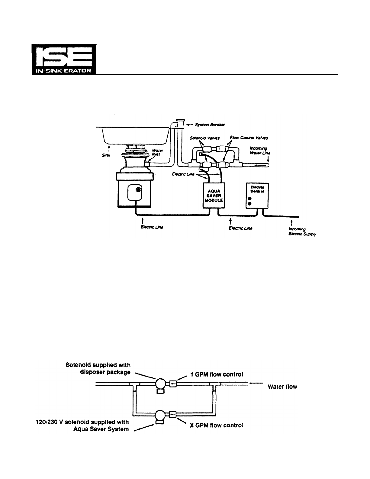
Recommended Installation of Aqua Saver System
Plumbing
Plumb the two water solenoid valves in parallel with each other and feed outlet to sink bowl or
disposer water inlet.
Important (See drawing below)
• The 1 GPM flow control (included with Aqua Saver) always plumbs to the solenoid valve supplied with the disposer
package, or the solenoid valve on an existing disposer installation.
• The X GPM flow control will be supplied as a standard item with a new In-Sink-Erator disposer package, or will be
in-line in an existing disposer installation. The Aqua Saver will work without the X GPM flow control, but it is
recommended as part of the installation. The X GPM flow control must always be plumbed to the 120/230 volt
solenoid valve supplied with the Aqua Saver package.
3
Page 4
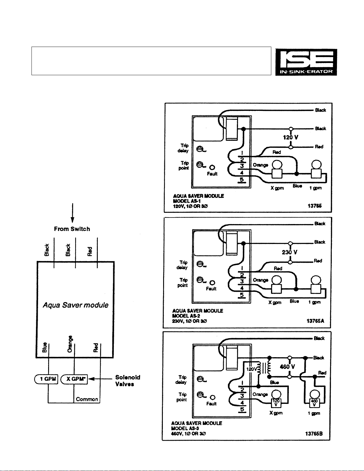
CONNECTING THE SOLENOID VALVES
General solenoid connection
Aqua Saver modules
The two solenoid valves are connected
to the Aqua Saver module by three
wires.
Note: When the disposer is initially
turned on, both solenoid valves will
operate. After approximately 15 seconds, the water flow to the disposer
will slow to 1 GPM, if you are not
grinding food waste.
• GPM varies by model
4
Page 5

ELECTRICAL CONNECTION DIAGRAMS
MANUAL REVERSING SWITCH - SINGLE PHASE
Reversing Switch Handle
115 volts
Single phase
MANUAL REVERSING SWITCH - SINGLE PHASE
Reversing Switch Handle
Motor
lead
wires
DIAGRAM 1
208/230 volts
Single phase
DIAGRAM 2 5
Page 6

ELECTRICAL CONNECTION DIAGRAMS
MANUAL REVERSING SWITCH-THREE PHASE
Reversing Switch Handle
MANUAL REVERSING SWITCH-THREE PHASE
Reversing Switch Handle
Motor
lead
wires
DIAGRAM 3
208/230 volts
Three phase
Motor
lead
460 volts
Three phase
wires
6
DIAGRAM 4
Page 7

ELECTRICAL CONNECTION DIAGRAMS
MANUAL SWITCH AND MAGNETIC STARTER - SINGLE PHASE
Line or
Power
Source
Aqua
Saver
Module
Motor
lead
wires
115 volts
Single phase
MANUAL SWITCH AND MAGNETIC STARTER - SINGLE PHASE
Line or
Power
Source
Aqua
Saver
Module
DIAGRAM 5
Motor
lead
wires
208-230 volts
Single phase
DIAGRAM 6 7
Page 8

+
ELECTRICAL CONNECTION DIAGRAMS
MANUAL SWITCH AND MAGNETIC STARTER - THREE PHASE
Line or
Power
Source
MANUAL SWITCH AND MAGNETIC STARTER - THREE PHASE
Motor
lead
wires
DIAGRAM 7
208-230 volts
Three phase
Line or
Power
Source
8
Motor
lead
wires
DIAGRAM 8
460 volts
Three phase
Page 9

ELECTRICAL CONNECTION DIAGRAMS
CC101 OR CC202 - SINGLE PHASE
Line or
Power
Source
CC101 OR CC202 - SINGLE PHASE
Motor
lead
wires
DIAGRAM 9
115 volts
Single phase
Line or
Power
Source
Motor
lead
208-230 volts
Single phase
wires
DIAGRAM 10 9
Page 10

Line
ELECTRICAL CONNECTION DIAGRAMS
CC101 OR CC202 - THREE PHASE
or
Power
Source
CC101 OR CC202 - THREE PHASE
Line or
Power
Source
Motor
lead
208-230 volts
Three phase
wires
DIAGRAM 11
Motor
lead
wires
460 volts
Three phase
10
DIAGRAM 12
Page 11

AQUA SAVER
120V,
10
OR
30
13765
CURRENT SENSING AND WARRANTY
Current sensing control
setup
1. Adjust the trip delay adjustment
at mid setting. This adjusts the
length of time the water runs at
full flow after grinding is completed.
Mid setting runs approximately 15
seconds.
2. With the disposer running but not
grinding:
a. Adjust the trip point control to
the maximum position. Water
to the disposer should be at
slow flow.
b. Turn the trip point control
counterclockwise until the red
fault light comes on. Water
flow should increase.
c. Turn the trip point control
clockwise until the red fault
light trips out. This is the set
MODULE MODEL AS-1
point.
Warranty Information
Your In-Sink-Erator Aqua Saver system is warranted for one year from date of installation.
This warranty covers both parts and labor for defects in workmanship or material only
(provided the labor is performed by an In-Sink-Erator Factory Authorized Service Agency).
This warranty does not apply if the Aqua Saver is installed with any commercial disposer
other than those manufactured by In-Sink-Erator. Also, the warranty does not apply if failure
is due to faulty or improper electrical installation, faulty or improper plumbing installation,
abuse, or accidental damage.
To obtain service, call the nearest In-Sink-Erator Factory Authorized Service Agency. For
the location of your nearest service agency, call toll free in the USA 1-800-558-5700 or 1800-561-1700 in Canada.
11
 Loading...