

Page 1
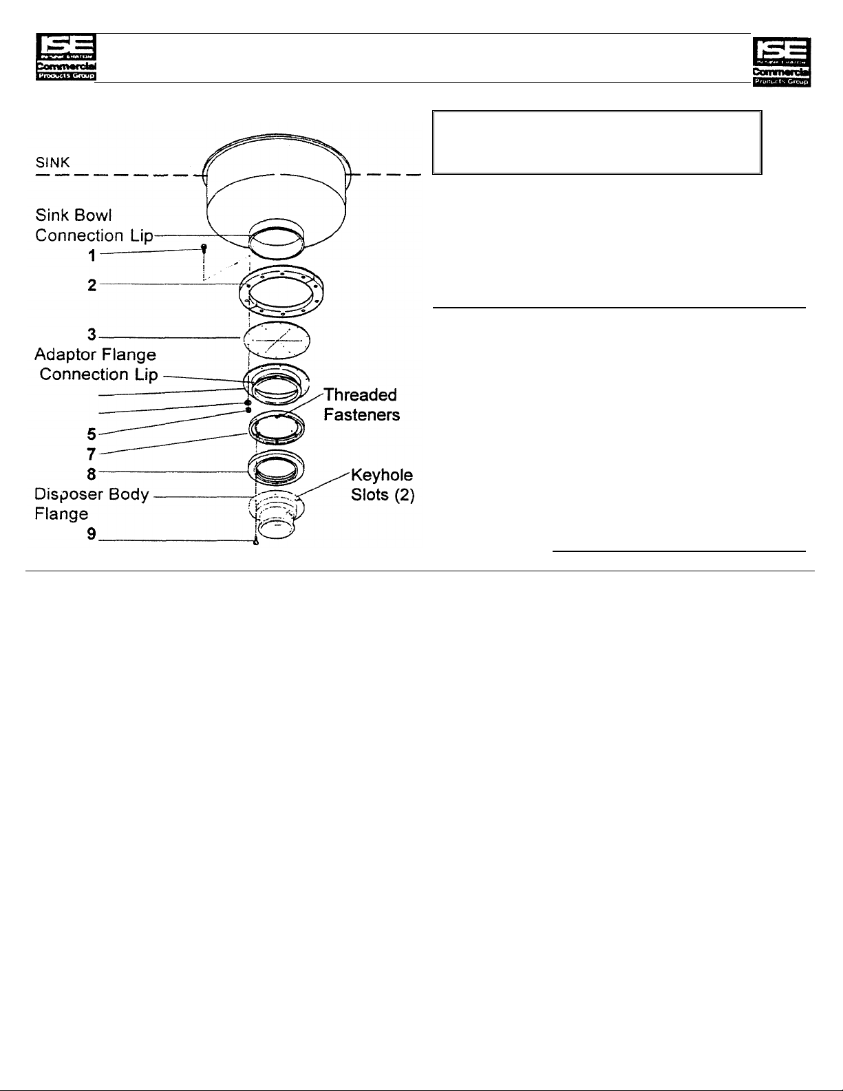
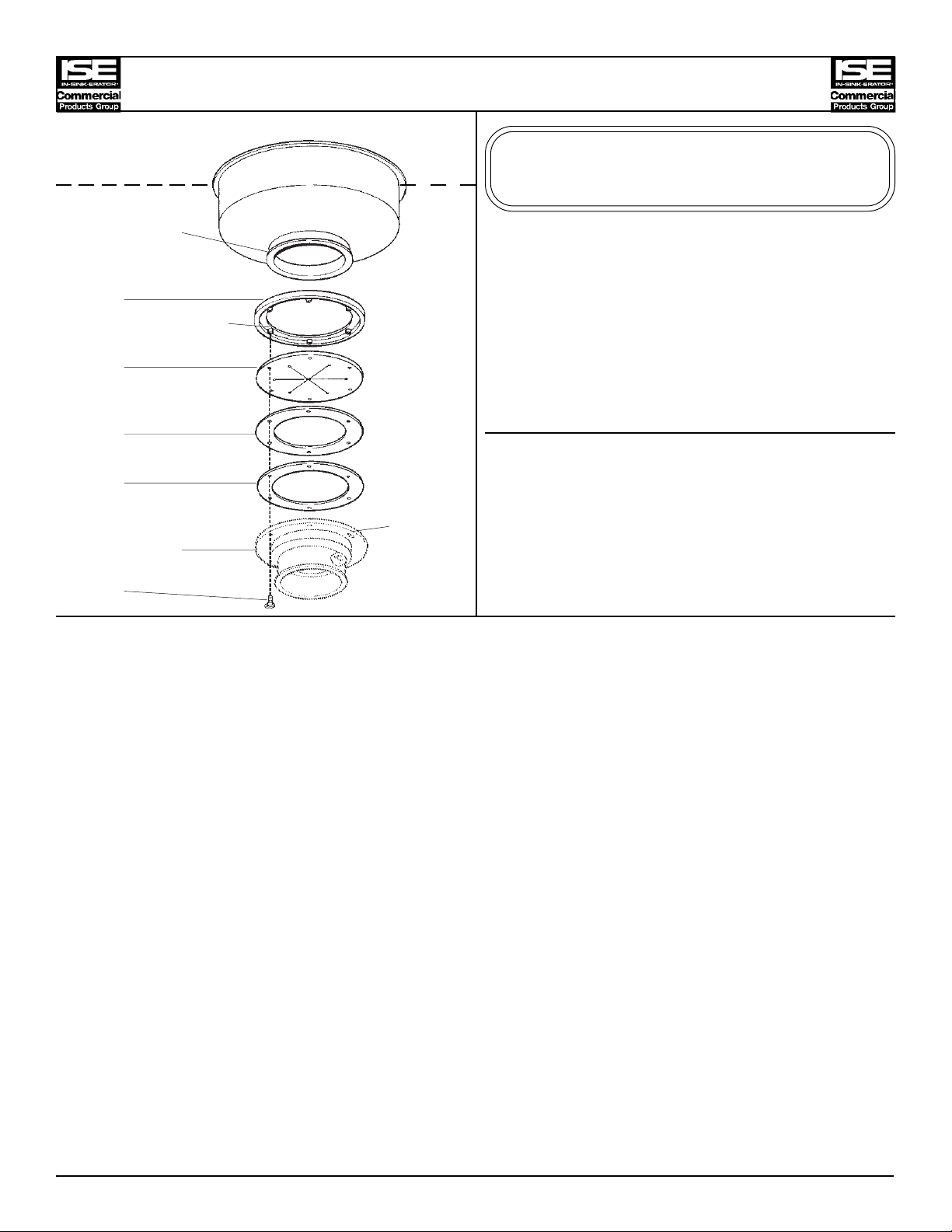
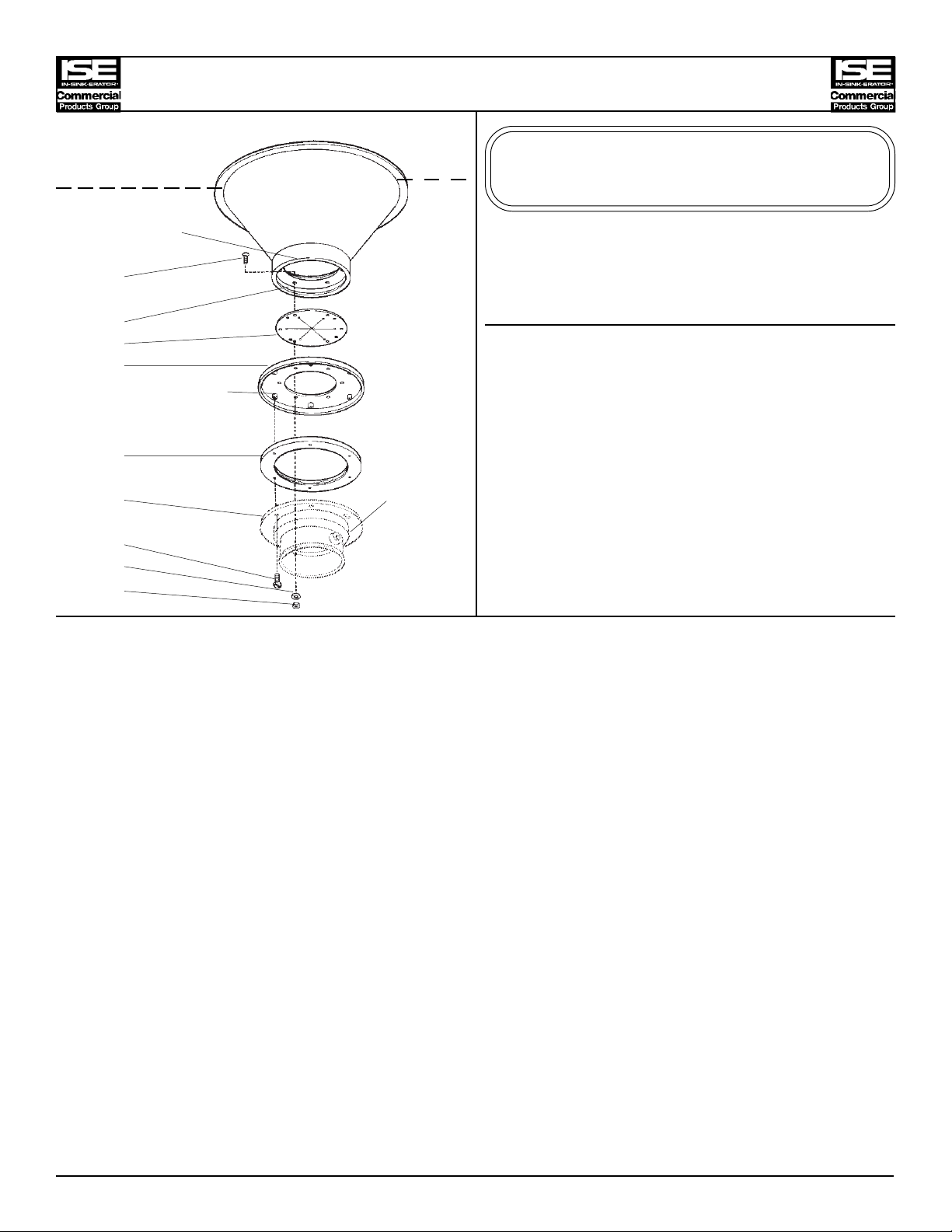
MOUNTING ADAPTOR (#11327)
This adaptor will fit a sink opening
8" I.D. and 9 1/4" O.D.
Part Numbers
I.D.
No.
1 1491 10 Screw
2 11279 1 Split Ring
3 11280 1 Flat Gasket
4 11278-A 1 Adapter Flange
5 11444 10 Lock Washer
6 3136 10 Nut
7 11004 1 Mounting Flange
8 11016 1 Mounting Gasket
9 1491 6 Screw
Part
No.
Qty Description
Installation Instructions (Suggested Assembly Method)
1. Place the split ring (2) around the sink bowl connection neck (located just above the sink bowl
connection lip). Insert screws (1) through the split ring (2), flat gasket (3), and adaptor flange (4). With
screws protruding through the adaptor flange (4), attach lock washers (5) and nuts (6). Tighten all
screws evenly.
2. Place mounting flange (7) over the adaptor flange connection lip (4). Push mounting flange (7) up out
of the way and fit inside groove of the mounting gasket (8) onto the adaptor flange connection lip (4).
3. Move mounting flange (7) down over mounting gasket (8). Be certain that the threaded fasteners in
the mounting flange (7) fit into recesses in the top of the mounting gasket (8).
4. Attach two screws (9) through opposite holes in the mounting gasket (8), and into the threaded
fasteners in the mounting flange (7). The screws (9) should be protruding approximately 1/4 inch
below the mounting gasket (8).
5. Position the disposer beneath the mounting gasket (8) and engage the two protruding screws in the
keyhole slots in the disposer body flange. Assemble the remaining screws (9) and turn the disposer
into place for plumbing connections. Tighten all screws evenly to secure the unit.
PN 13966 (REV. 11/1/96)
Page 2
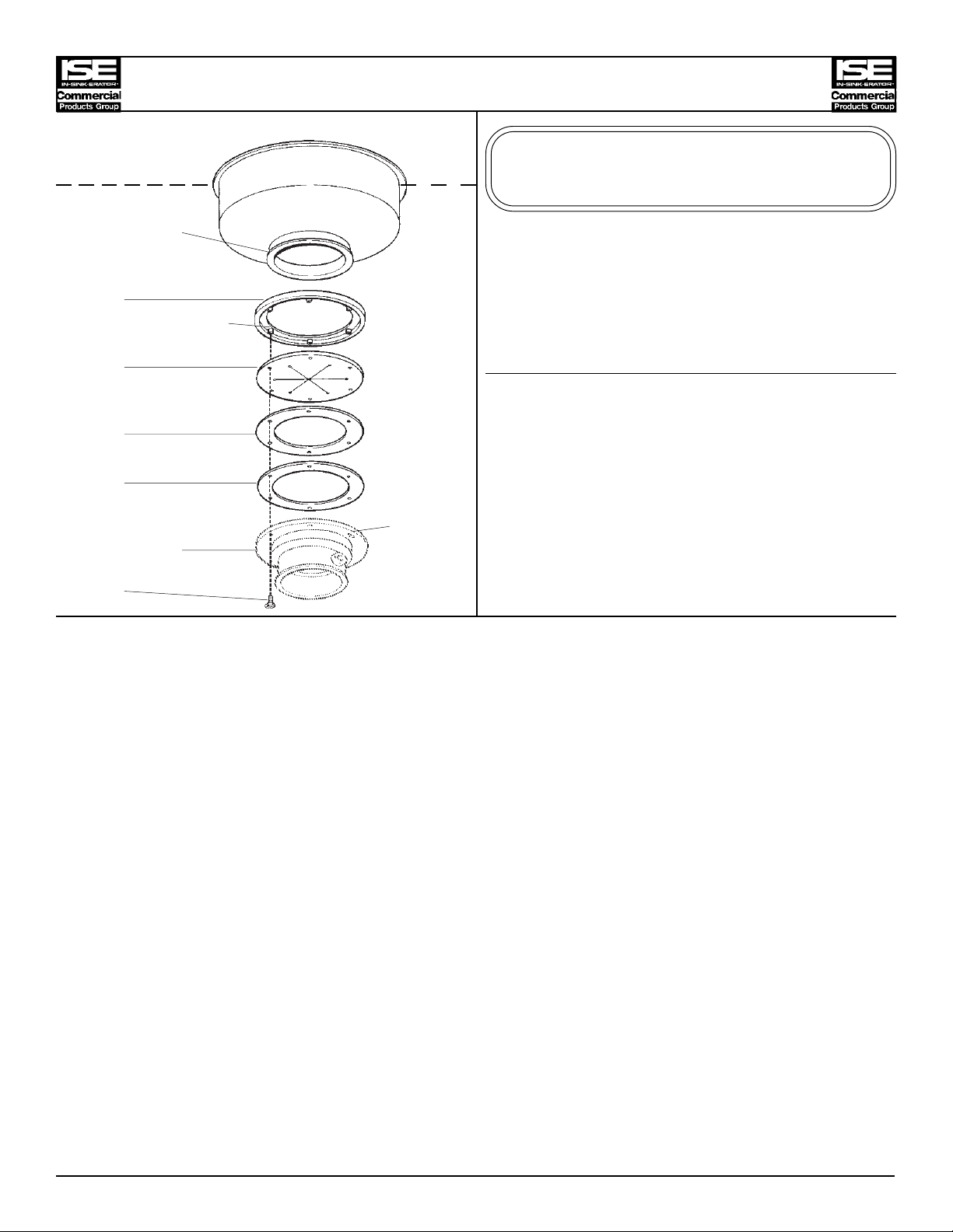
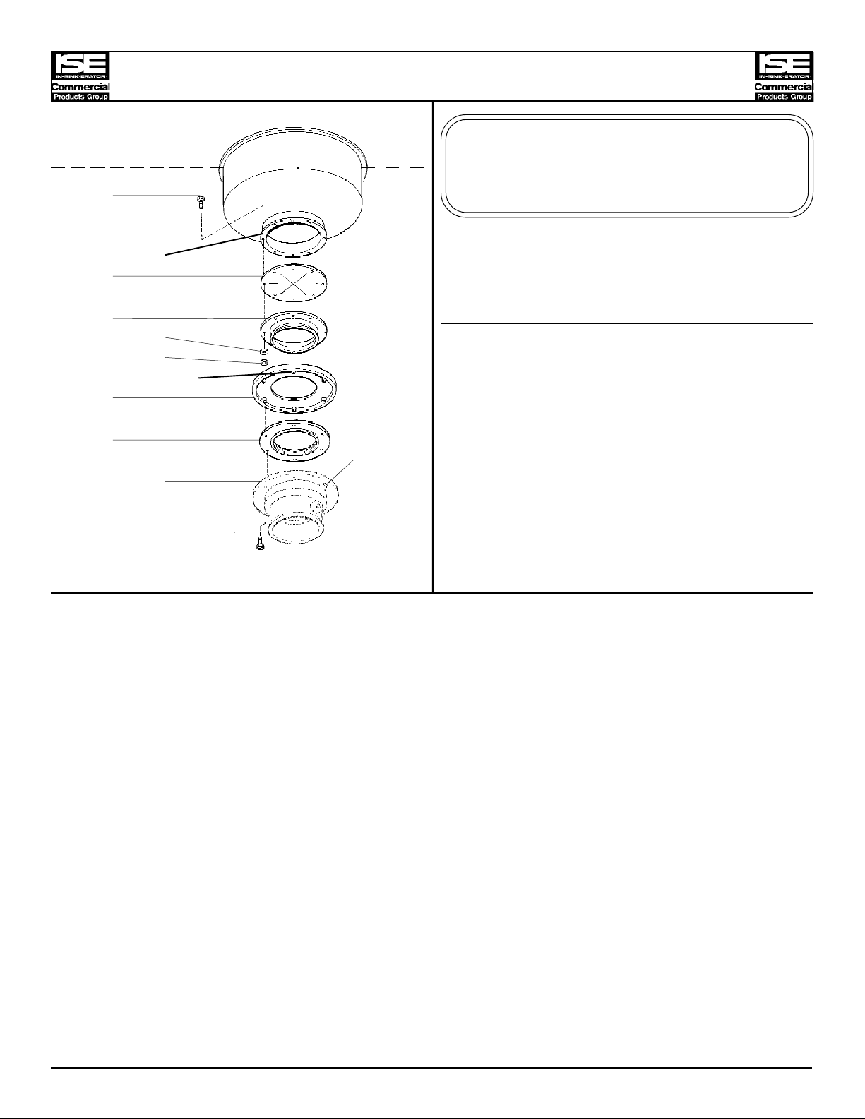
MOUNTING ADAPTOR (# 11327-A)
This adaptor will fit a sink opening of:
SINK
Sink Bowl
Connection Lip
1
Threaded Fasteners
2
3
4
Keyhole
Disposer Body Slots (2)
Flange
5
4 1/2" I.D. and 5 1/8" O.D.
Part Numbers
I.D. Part
No. No. Qty Description
1 11004-A 1 Mounting Flange
2 11342-A 1 Mounting Gasket
3 11293 1 Support Ring
4 11292 1 Flat Gasket
5 1491 6 Screw
Installation Instructions (Suggested Assembly Method)
1. Place mounting flange (1) up over existing sink bowl connection lip. It may require a slight force
fit.
2. Push mounting flange (1) up out of the way and fit inside groove of mounting gasket (2) onto the
sink bowl connection lip.
3. Move mounting flange (1) down over mounting gasket (2). Be certain that the threaded fasteners
in the mounting flange (1) fit into recesses in the top of the mounting gasket (2).
4. Attach two screws (5) through opposite holes in the flat gasket (4), support ring (3), mounting
gasket (2) and into the threaded fasteners in the mounting flange (1). The screws ( 5) should be
protruding approximately 1/4 inch below the flat gasket (4).
5. Position the disposer beneath the flat gasket (4) and engage the two protruding screws in the
keyhole slots in the disposer body flange. Assemble the remaining screws (5) and turn the
disposer into place for plumbing connections. Tighten all screws evenly to secure the unit.
PN 13966-A (REV. 11/1/96)
Page 3
SINK
Sink Bowl
Connection Lip
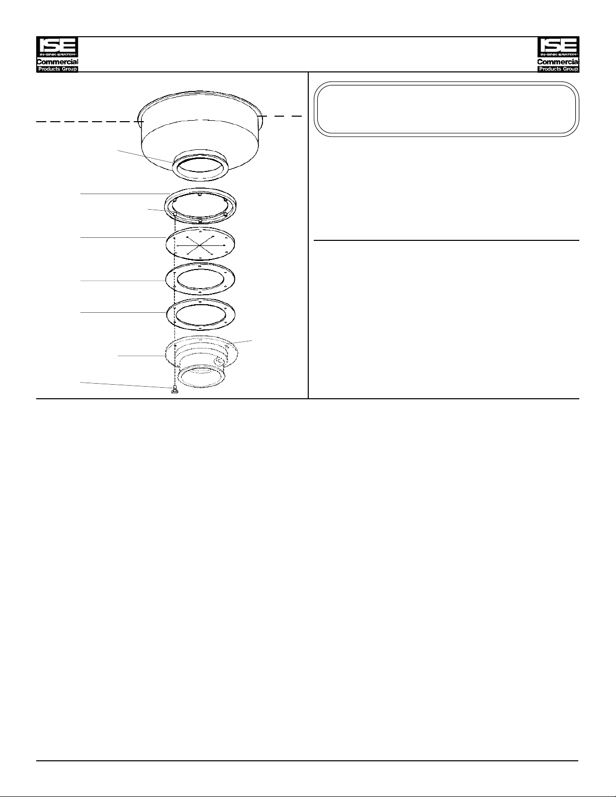
MOUNTING ADAPTOR (# 11327-B)
This adaptor will fit a sink opening of:
6" I.D. and 7 3/16" O.D.
1
Threaded Fasteners
2
3
4
Keyhole
Disposer Body Slots (2)
Flange
5
I.D. Part
No. No. Qty Description
1 11004 1 Mounting Flange
2 11342 1 Mounting Gasket
3 11293-B 1 Support Ring
4 11292 1 Flat Gasket
5 1491 6 Screw
Part Numbers
Installation Instructions (Suggested Assembly Method)
1. Place mounting flange (1) up over existing sink bowl connection lip. It may require a slight force
fit.
2. Push mounting flange (1) up out of the way and fit inside groove of mounting gasket (2) onto sink
bowl connection lip.
3. Move mounting flange (1) down over mounting gasket (2). Be certain that the threaded fasteners
in the mounting flange (1) fit into recesses in the top of the mounting gasket (2).
4. Attach two screws (5) through opposite holes in the flat gasket (4), support ring (3), mounting
gasket (2) and into the threaded fasteners in the mounting flange (1). The screws ( 5) should be
protruding approximately 1/4 inch below the flat gasket (4).
5. Position the disposer beneath the flat gasket (4) and engage the two protruding screws in the
keyhole slots in the disposer body flange. Assemble the remaining screws (5) and turn the
disposer into place for plumbing connections. Tighten all screws evenly to secure the unit.
PN 13966-B (REV. 11/1/96)
Page 4
SINK
Sink Bowl
Connection Lip
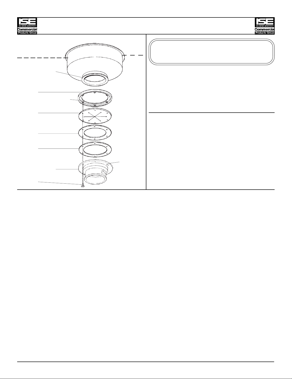
MOUNTING ADAPTOR (# 11327-C)
This adaptor will fit a sink opening of:
5 1/4" I.D. and 5 11/16" O.D.
1
Threaded Fasteners
2
3
4
Keyhole
Disposer Body Slots (2)
Flange
5
I.D. Part
No. No. Qty Description
1 11004-D 1 Mounting Flange
2 11342-B 1 Mounting Gasket
3 11293-A 1 Support Ring
4 11292 1 Flat Gasket
5 1491 6 Screw
Part Numbers
Installation Instructions (Suggested Assembly Method)
1. Place mounting flange (1) up over existing sink bowl connection lip. It may require a slight force
fit.
2. Push mounting flange (1) up out of the way and fit inside groove of mounting gasket (2) onto sink
bowl connection lip.
3. Move mounting flange (1) down over mounting gasket (2). Be certain that the threaded fasteners
in the mounting flange (1) fit into recesses in the top of the mounting gasket (2).
4. Attach two screws (5) through opposite holes in the flat gasket (4), support ring (3), mounting
gasket (2) and into the threaded fasteners in the mounting flange (1). The screws ( 5) should be
protruding approximately 1/4 inch below the flat gasket (4).
5. Position the disposer beneath the flat gasket (4) and engage the two protruding screws in the
keyhole slots in the disposer body flange. Assemble the remaining screws (5) and turn the
disposer into place for plumbing connections. Tighten all screws evenly to secure the unit.
PN 13966-C (REV. 11/1/96)
Page 5
MOUNTING ADAPTOR (# 11327-D)
This adaptor will fit a sink opening of:
SINK
Sink Bowl
Connection Lip
1
Threaded Fasteners
2
3
4
Keyhole
Disposer Body Slots (2)
Flange
5
6" I.D. and 6 1/2" O.D.
Part Numbers
I.D. Part
No. No. Qty Description
1 11004-B 1 Mounting Flange
2 11342 1 Mounting Gasket
3 11293-B 1 Support Ring
4 11292 1 Flat Gasket
5 1491 6 Screw
Installation Instructions (Suggested Assembly Method)
1. Place mounting flange (1) up over existing sink bowl connection lip. It may require a slight force
fit. Do not use existing LOOSE RING.
2. Push mounting flange (1) up out of the way and fit inside groove of mounting gasket (2) onto the
sink bowl connection lip.
3. Move mounting flange (1) down over mounting gasket (2). Be certain that the threaded fasteners
in the mounting flange (1) fit into recesses in the top of the mounting gasket (2).
4. Attach two screws (5) through opposite holes in the flat gasket (4), support ring (3), mounting
gasket (2) and into the threaded fasteners in the mounting flange (1). The screws ( 5) should be
protruding approximately 1/4 inch below the flat gasket (4).
5. Position the disposer beneath the flat gasket (4) and engage the two protruding screws in the
keyhole slots in the disposer body flange. Assemble the remaining screws (5) and turn the
disposer into place for plumbing connections. Tighten all screws evenly to secure the unit.
PN 13966-D (REV. 11/1/96)
Page 6
SINK
1
Sink Bowl
Connection Lip
2
3
4
5
Threaded Fastener
6
MOUNTING ADAPTOR (# 11327-E)
This adaptor will fit a sink opening of:
9" I.D. and 12 1/8" O.D.
with 11 1/8"bolt hole cirlce
Part Numbers
I.D. Part
No. No. Qty Description
1 1491 8 Screw
2 11280-A 1 Flat Gasket
3 11278-B 1 Adaptor Flange
7
4 11444 8 Lock Washer
Keyhole
Disposer Body Slots (2)
5 3136 8 Nut
Flange
6 11004 1 Mounting Flange
8
7 11016 1 Mounting Gasket
8 1491 6 Screw
Installation Instructions (Suggested Assembly Method)
1. Insert screws (1) through the sink bowl connection lip, flat gasket (2), and adaptor flange (3).
With screws protruding through the adaptor flange (3), attach lock washers (4) and nuts (5).
Tighten all screws evenly.
2. Place the mounting flange (6) over the adaptor flange connection lip (3). Push mounting flange
(6) up out of the way and fit the mounting gasket (7) onto the lip of the adaptor flange (3)
3. Move mounting flange (6) down over mounting gasket (7). Be certain that the threaded fasteners
in the mounting flange (6) fit into recesses in the top of the mounting gasket (7).
4. Attach two screws (8) through opposite holes in the mounting gasket (7), and into the threaded
fasteners in the mounting flange (6). The screws (8) should be protruding approximately 1/4 inch
below the mounting gasket (7).
5. Position the disposer beneath the mounting gasket (7) and engage the two protruding screws in
the keyhole slots in the disposer body flange. Assemble the remaining screws (8) and turn the
disposer into place for plumbing connections. Tighten all screws evenly to secure the unit.
PN 13966-E (REV. 11/1/96)
Page 7
MOUNTING ADAPTOR (# 11327-G)
This adaptor will fit a sink opening of:
SINK
Sink Bowl
Connection Lip
Threaded Fastener
1
2
Keyhole
Disposer Body Flange Slots (2)
3
7" I.D. and 7 3/8" O.D.
Part Numbers
I.D. Part
No. No. Qty Description
1 11004-C 1 Mounting Flange
2 11341 1 Mounting Gasket
3 1491 6 Screw
Installation Instructions (Suggested Assembly Method)
1. Place mounting flange (1) up over existing sink bowl connection lip. It may require a slight force
fit.
2. Push mounting flange (1) up out of the way and fit inside groove of mounting gasket (2) onto the
sink bowl connection lip.
3. Move mounting flange (1) down over the mounting gasket (2). Be certain that the threaded
fasteners in the mounting flange (1) fit into the recesses in the top of the mounting gasket (2).
4. Attach two screws (3) through opposite holes in the mounting gasket (2) and into the threaded
fasteners in the mounting flange (1). The screws (3) should be protruding approximately 1/4 inch
below the mounting gasket (2)
5. Position the disposer beneath the mounting gasket (2) and engage the two protruding screws in
the keyhole slots in the disposer body flange. Assemble the remaining screws (3) and turn the
disposer into place for plumbing connections. Tighten all screws evenly to secure the unit.
PN 13966-G (REV. 11/1/96)
Page 8
SINK
Sink Bowl
Connection Lip
1
MOUNTING ADAPTOR (# 11327-H)
This adaptor will fit a sink opening of:
4 1/2" I.D. and 6 7/8" O.D.
5 7/8" I.D. and 6 1/2" O.D.
5 7/8" I.D. and 6 7/8" O.D.
with 5 1/2" bolt hole circle
Part Numbers
2
3
Threaded Fasteners
4
5
6
Disposer Body
Flange Keyhole
7
I.D. Part
No. No. Qty Description
1 11294 6 Screw
2 11292-C 1 Flat Gasket
3 11189-A 1 Mounting Flange
4 11180 6 Washer
5 11179 6 Nut
6 11016 1 Mounting Gasket
7 1491 6 Screw
Installation Instructions (Suggested Assembly Method)
1. Insert screws (1) through the sink bowl connection lip (or loose ring), flat gasket (2) and mounting
flange (3). With screws protruding through the mounting flange (3) attach washers (4) and nuts
(5). Tighten all screws evenly.
2. Position the disposer for plumbing hookup and check the location of the keyhole slots in the
disposer body flange.
3. Attach two screws (7) through opposite holes in the mounting gasket (6) and into the threaded
fasteners in the mounting flange (3). The screws (7) should be protruding approximately 1/4 inch
below the mounting gasket (6).
4. Position the disposer beneath the mounting gasket (6) and engage the two protruding screws in
the keyhole slots in the disposer body flange. Assemble the remaining screws (7). Tighten all
screws evenly to secure the unit.
PN 13966-H (REV. 11/1/96)
Page 9
SINK
Sink Bowl
Connection Lip
MOUNTING ADAPTOR (# 11327-J)
This adaptor will fit a sink opening of:
5" I.D. and 5 7/8" O.D.
Part Numbers
1
2
3
4
Threaded Fasteners
5
Disposer Body
Flange Keyhole
6
7
8
I.D. Part
No. No. Qty Description
1 11294 6 Screw
2 11592 1 Clamping Ring
3 11292-B 1 Flat Gasket
4 11189-C 1 Mounting Flange
5 11016 1 Mounting Gasket
6 1491 6 Screw
7 11180 6 Washer
8 11179 6 Nut
Installation Instructions (Suggested Assembly Method)
1. Place the clamping ring (2) down through the opening so that it rests on the sink bowl connection
lip. If the opening has a small ridge on the inside above the lip, a slight force fit may be
necessary to push the ring down to the lip.
2. Insert screws (1) through the clamping ring (2), flat gasket (3) and mounting flange (4). With
screws protruding through the mounting flange (4), attach washers (7) and nuts (8). Tighten all
screws evenly.
3. Position the disposer for plumbing hookup and check the location of the keyhole slots in the
disposer body flange.
4. Attach two screws (6) through opposite holes in the mounting gasket (5) and into the threaded
fasteners in the mounting flange (4). The screws (6) should be protruding approximately 1/4 inch
below the mounting gasket (5).
5. Position the disposer beneath the mounting gasket (5) and engage the two protruding screws in
the keyhole slots in the disposer body flange. Assemble the remaining screws (6). Tighten all
screws evenly to secure the unit.
PN 13966-J (REV. 11/1/96)
Page 10

MOUNTING ADAPTOR (# 11327-K)
This adaptor will fit a sink opening of:
Sink
Sink Bowl
Connection Lip
1
Threaded Fasteners
2
3
4
Keyhole
Disposer Body Slots (2)
Flange
5
6" I.D. and 6 7/8" O.D.
Part Numbers
I.D. Part
No. No. Qty Description
1 11004-E 1 Mounting Flange
2 11342 1 Mounting Gasket
3 11293-B 1 Metal Support Ring
4 11292 1 Flat Gasket
5 1491 6 Screw
Installation Instructions (Suggested Assembly Method)
1. Place adaptor mounting flange (1) up over existing sink bowl connection lip. It may require a
slight force fit.
2. Push mounting flange (1) up out of the way and fit inside groove of mounting gasket (2) onto the
sink bowl connection lip.
3. Move mounting flange (1) down over mounting gasket (2). Be certain that the threaded fasteners
in the mounting flange (1) fit into recesses in the top of the mounting gasket (2).
4. Attach two screws (5) through opposite holes in the flat gasket (4), metal support ring (3),
mounting gasket (2) and into the threaded fasteners in the mounting flange (1). The screws (5)
should be protruding approximately 1/4 inch below the flat gasket (4).
5. Position the disposer beneath the flat gasket (4) and engage the two protruding screws in the
keyhole slots in the disposer body flange. Assemble the remaining screws (5) and turn the
disposer into place for plumbing connections. Tighten all screws evenly to secure the unit.
PN 13966-K (REV. 11/1/96)
Page 11

MOUNTING ADAPTOR (# 11599)
This adaptor will fit a sink opening of:
SINK
1
Sink Bowl
Connection Lip
2
Threaded Fasteners
3
4
5
6 Keyhole
Disposer Body Slots
Flange
7
4 1/2" I.D. and 6 1/2 O.D.
w/ 5 1/2" bolt hole circle
Part Numbers
I.D. Part
No. No. Qty Description
1 1491 6 Screw
2 11292-C 1 Flat Gasket
3 11189-A 1 Mounting Flange
4 11180 6 Washer
5 11179 6 Nut
6 11016 1 Mounting Gasket
7 1491 6 Screw
Installation Instructions (Suggested Assembly Method)
1. Insert screws (1) through the holes of the sink bowl connection lip, flat gasket (2) and mounting
flange (3). With screws protruding through the mounting flange (3), attach washers (4) and nuts
(5). Tighten all screws evenly.
2. Position the disposer for plumbing hookup and check the location of the keyhole slots in the
disposer body flange.
3. Attach two screws (7) through opposite holes in the mounting gasket (6) and into the threaded
fasteners in the mounting flange (3). The screws (7) should be protruding approximately 1/4 inch
below the mounting gasket (6).
4. Position the disposer beneath the mounting gasket (6) and engage the two protruding screws in
the keyhole slots in the disposer body flange. Assemble the remaining screws (7). Tighten all
screws evenly to secure the unit.
PN 13966-L (REV. 11/1/96)
Page 12

SINK
Sink Bowl
Connection Lip
1
2
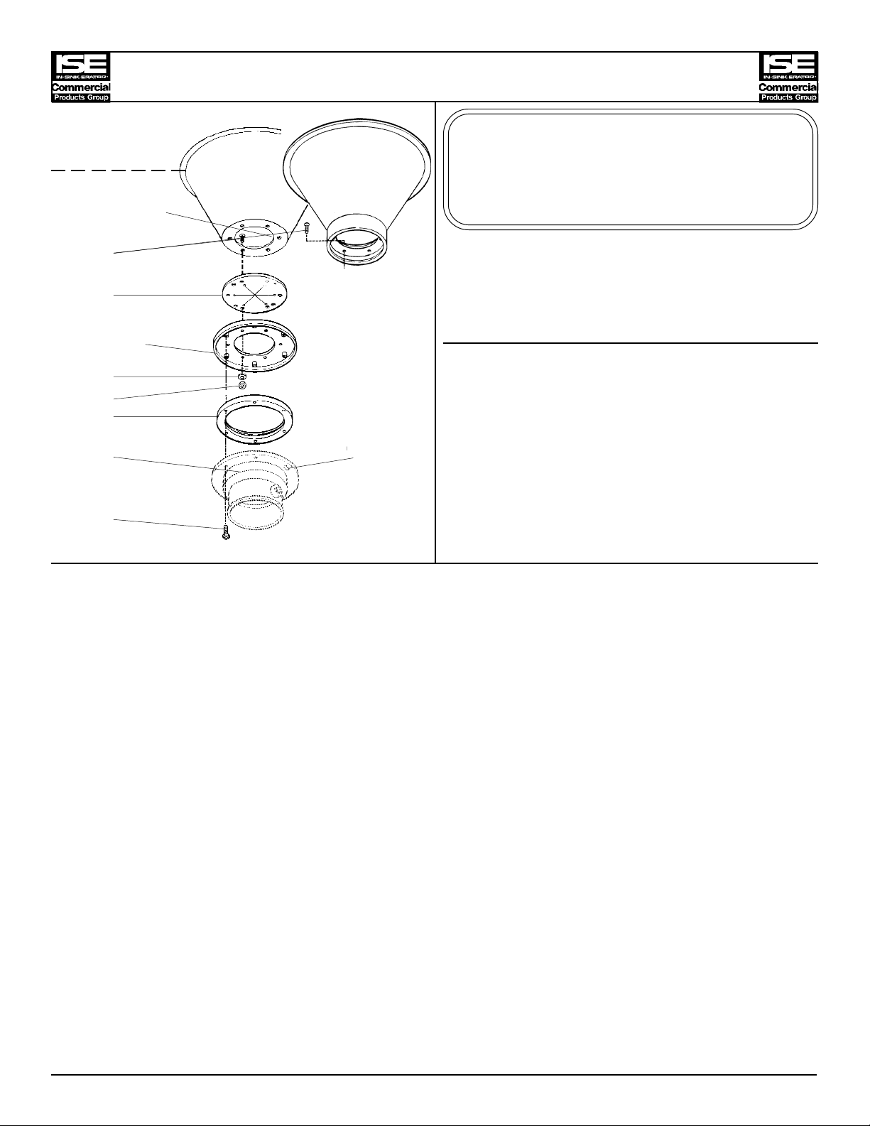
MOUNTING ADAPTOR (# 11599-A)
This adaptor will fit a sink opening of:
7" I.D. and 7 3/4" O.D.
Part Numbers
I.D. Part
No. No. Qty Description
3
Adaptor Flange
Connection Lip
1 1491 10 Screw
2 12613 1 Split Ring
3 12614 1 Flat Gasket
Threaded
Fasteners
5
7
4 12664-A 1 Spacer Sleeve
5 11444 10 Lock Washer
6 11179 10 Nut
8 Keyhole
Disposer Body Slots (2)
Flange
9
7 11004-C 1 Mounting Flange
8 11341 1 Mounting Gasket
9 1491 6 Screw
Installation Instructions (Suggested Assembly Method)
1. Place the split ring (2) around the sink bowl connection neck (located just above the sink bowl
connection lip). Insert screws (1) through the split ring (2), flat gasket (3), and spacer sleeve (4).
With screws protruding through the spacer sleeve (4), attach lock washers (5) and nuts (6).
Tighten all screws evenly.
2. Place mounting flange (7) over the spacer sleeve connection lip (4). Push mounting flange (7)up
out of the way and fit inside groove of the mounting gasket (8) onto the spacer sleeve connection
lip (4).
3. Move mounting flange (7) down over mounting gasket (8). Be certain that the threaded fasteners
in the mounting flange (7) fit into recesses in the top of the mounting gasket (8).
4. Attach two screws (9) through opposite holes in the mounting gasket (8), and into the threaded
fasteners in the mounting flange (7). The screws (9) should be protruding approximately 1/4 inch
below the mounting gasket (8).
5. Position the disposer beneath the mounting gasket (8) and engage the two protruding screws in
the keyhole slots in the disposer body flange. Assemble the remaining screws (9) and turn the
disposer into place for plumbing connections. Tighten all screws evenly to secure the unit.
PN 13966-M (REV. 11/1/96)
Page 13

MOUNTING ADAPTOR (# 11599-B)
This adaptor will fit a sink opening of:
SINK
1
Sink Bowl
Connection Lip
2
3
4
5
Adaptor Flange Threaded
Connection Lip Fasteners
6
7
Keyhole
Disposer Body Slots (2)
Flange
8
7" I.D. and 8 1/2 " O.D.
with 8 1/16" bolt hole circle
(10 bolts)
Part Numbers
I.D. Part
No. No. Qty Description
1 1468 10 Screw
2 12614 1 Flat Gasket
3 12664-A 1 Adapter Flange
4 11444 10 Washer
5 11179 10 Nut
6 11004-C 1 Mounting Flange
7 11341 1 Mounting Gasket
8 1491 6 Screw
Installation Instructions (Suggested Assembly Method)
1. Place flat gasket (2) on the sink bowl connection lip. Insert screws (1) through the sink bowl
connection lip, flat gasket (2), and adaptor flange (3). With screws protruding through the
adaptor flange (3), attach washers (4) and nuts (5). Tighten all screws evenly.
2. Place mounting flange (6) over adaptor flange connection lip (3). Push mounting flange (6)up
out of the way and fit inside groove of mounting gasket (7) onto the adaptor flange connection lip
(3).
3. Move mounting flange (6) down over mounting gasket (7). Be certain that the threaded fasteners
in the mounting flange (6) fit into recesses in the top of the mounting gasket (7).
4. Attach two screws (8) through opposite holes in the mounting gasket (7), and into the threaded
fasteners in the mounting flange (6). The screws (8) should be protruding approximately 1/4 inch
below the mounting gasket (7).
5. Position the disposer beneath the mounting gasket (7) and engage the two protruding screws in
the keyhole slots in the disposer body flange. Assemble the remaining screws (8) and turn the
disposer into place for plumbing connections. Tighten all screws evenly to secure the unit.
PN 13966-N (REV. 11/1/96)
Page 14

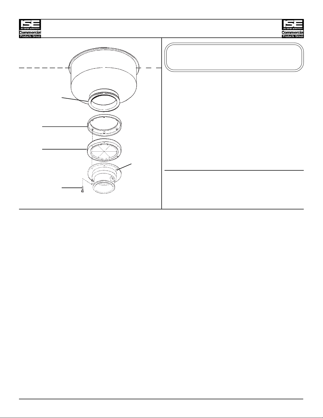
MOUNTING ADAPTOR (# 11599-E)
SINK
Sink Bowl
Connection Lip
Threaded Fasteners
1
2
Keyhole
Disposer Body Flange Slots (2)
3
This adaptor will fit a sink opening of:
6 5/8" I.D. and 7 1/8" O.D.
Part Numbers
I.D. Part
No. No. Qty Description
1 11004 1 Mounting Flange
2 11016 1 Mounting Gasket
3 1491 6 Screw
Installation Instructions (Suggested Assembly Method)
1. Place mounting flange (1) up over existing collar adaptor connection lip. It may require a slight
force fit.
2. Push mounting flange (1) up out of the way and fit mounting gasket (2) onto the sink bowl
connection lip.
3. Move mounting flange (1) down over the mounting gasket (2). Be certain that the threaded
fasteners in the mounting flange (1) fit into recesses in the top of the mounting gasket (2).
4. Attach two screws (3) through opposite holes in the mounting gasket (2) and into the threaded
fasteners in the mounting flange (1). The screws (3) should be protruding about 1/4 inch below
the gasket (2).
5. Position the disposer beneath the mounting gasket (1) and engage the two protruding screws in
the keyhole slots in the disposer body flange. Assemble the remaining screws (2) and turn the
disposer into place for plumbing connections. Tighten all screws evenly to secure the unit.
PN 13966-P (REV. 11/1/96)
Page 15

SINK
SinkBowl
Raised Bead
1 Connection
MOUNTING ADAPTOR (# 11599-H)
Thisadaptor will fita sink opening of:
6 5/8" I.D. and NO flange with
raised bead in the straight neck
Lip
2 Threaded
Fasteners
3
4
Keyhole
I.D. Part
No. No. Qty Description
1 1468 10 Scre w
2 12681 1 SplitRing
3 11306-D 1 MountingFlange
Part Numbers
Slots (2)
DisposerBody
Flange
4 11341 1 Mounting Gasket
5 3135 6 Scr ew
5
Installation Instructions (Suggested Assembly Method) - SUPPORT LEGS ARE REQUIRED
1. Place the split ring (2) over and above sink bowl raised bead.
2. Placemounting flange (3) over the sink bowl connection neck. Attach screws (1) through the split
ring (2) and into the threaded holes in the mounting flange (3). Tighten screws evenly.
3. Attachtwo screws (5) through opposite holes in the mounting gasket (4),andinto the threaded
holes in the mounting flange(3). The screws (5) should be protruding approximately 1/4 inch
below the mounting gasket (4).
4. Positionthe disposer beneath the mounting gasket (4)and engage the two protruding screws in
the keyhole slots in the disposer body flange. Assemble the remaining screws (5)and turn the
disposer into place for plumbing connections. Tighten all screws evenly tosecure the unit.
5. Extendthe adjustable legs of thedisposer to provide support fromthe floor.
NOTE: Disposersfrom3H.P.through10H.P. have factory assembledlegs.
Disposersfrom1/2H.P.through2 H.P. require twoaccessorylegs.
PN 13966-S (REV. 3/6/98)
Page 16

MOUNTING ADAPTOR (# 11599-K)
SINK
Throat
1
2
1
3
Threaded
Fasteners
4
5 Keyhole
Disposer Body Slots (2)
Flange
6
This adaptor will fit a sink opening of:
8" I.D. and NO Flange
Part Numbers
I.D. Part
No. No. Qty Description
1 13119 2 Clamping Band
2 13120-A 1 Rubber Sleeve
3 13118 1 Sleeve Adaptor
4 11004-C 1 Mounting Flange
5 11341 1 Mounting Gasket
6 1491 6 Screw
Installation Instructions (Suggested Assembly Method) - SUPPORT LEGS ARE REQUIRED.
1. Assemble the rubber sleeve (2) to the throat of the sink bowl with one of the clamping bands (1).
2. Insert the lip of the sleeve adaptor (3) through the mounting flange (4) and into the groove of the
mounting gasket (5).
3. Place the sleeve adaptor (3), mounting gasket (5) and mounting flange assembly on the top of the
disposer body flange. Be certain that the threaded fasteners in the mounting flange (4) fit into the
recesses in the top of the mounting gasket (5).
4. Fasten screws (6) through holes in disposer body flange, mounting gasket (5) and into the
threaded fasteners in the mounting flange (4). Tighten screws evenly.
5. Position the disposer under the rubber sleeve (3). Extend the adjustable legs of the disposer to
provide support from the floor.
NOTE: Disposers from 3 H.P. through 10 H.P. have factory assembled legs.
Disposers from 1/2 H.P. through 2 H.P. require two accessory legs.
6. Turn the disposer into position for plumbing connections. Slide the sleeve adaptor (3) into the
bottom of the rubber sleeve (2) and tighten with the other clamping band (1). Adjust the support
legs for final positioning.
PN 13966-T (REV. 11/1/96)
Page 17

MOUNTING ADAPTOR (# 11599-N)
This adaptor will fit a sink opening of:
4 7/16" I.D. and NO flange with
raised bead in the straight neck
Part Numbers
I.D.
No.
1 13242-B 1 Split Ring
2 11306-E 1 Mounting Flange
3 11184 6 Screw
4 11342-A 1 Mounting Gasket
5 3135 6 Screw
Part
No.
Qty Description
installation Instructions (Suggested Assembly Method) - SUPPORT LEGS ARE REQUIRED
1. Place the split ring (1) over and above sink bowl raised bead.
2. Place mounting flange (2) over the sink bowl connection neck. Attach screws (3) through the mounting
flange (3) and into the threaded holes in the split ring (2). Tighten screws evenly.
3. Attach two screws (5) through opposite holes in the mounting gasket (4), and into the threaded holes in
the mounting flange (2). The screws (5) should be protruding approximately 1/4 inch below the mounting
gasket (4).
4. Position the disposer beneath the mounting gasket (4) and engage the two protruding screws in the
keyhole slots in the disposer body flange. Assemble the remaining screws (5) and turn the disposer into
place for plumbing connections. Tighten all screws evenly to secure the unit.
5. Extend the adjustable legs of the disposer to provide support from the floor.
NOTE: Disposers from 3 H.P. through 10 H. P. have factory assembled legs.
Disposers from 1/2 H.P. through 2 H.P. require two accessory legs.
PN 13966-U (Rev. 11/1/96)
Page 18

MOUNTING ADAPTOR (# 11599-P)
This adaptor will fit a sink opening of:
6" I.D. and 8 3/4" O.D.
with 8-1/6" bolt hole circle (6 bolts)
Part Numbers
I.D.
No.
1 1468 6 Screw
2 11180 6 Washer
3 11292 1 Flat Gasket
4 12664-B 1 Adapter Flange
5 11180 6 Washer
6 3136 6 Nut
7 11004-C 1 Mounting Flange
8 11341 1 Mounting Gasket
9 1491 6 Screw
Part
No. Qty Description
Installation Instructions (Suggested Assembly Method)
1. Place flat gasket (2) on the sink bowl connection lip. Insert screws (1) through washer (2), sink bowl
connection lip, flat gasket (3), and adaptor flange (4). With screws protruding through the adaptor
flange (4), attach washers (5) and nuts (6). Tighten all screws evenly.
2. Place mounting flange (7) over adaptor flange connection lip (4). Push mounting flange (6) up out of
the way and fit inside groove of mounting gasket (8) onto the adaptor flange connection lip (4).
3. Move mounting flange (7) down over mounting gasket (8). Be certain that the threaded fasteners in the
mounting flange (7) fit into recesses in the top of the mounting gasket (8).
4. Attach two screws (9) through opposite holes in the mounting gasket (8), and into the threaded
fasteners in the mounting flange (7). The screws (9) should be protruding approximately 1/4 inch below
the mounting gasket (8).
5. Position the disposer beneath the mounting gasket (8) and engage the two protruding screws in the
keyhole slots in the disposer body flange. Assemble the remaining screws (9) and turn the disposer into
place for plumbing connections. Tighten all screws evenly to secure the unit.
PN 13966-W (REV. 11/1/96)
Page 19

MOUNTING ADAPTOR (# 11599-S)
This adaptor will fit a sink opening of:
SINK
1
Sink Bowl
Connection Lip
2
Threaded Fasteners
3
4
5
6 Keyhole
Disposer Body Slots
Flange
7
4 3/4" I.D. and 6 1/2 O.D.
w/ 5 1/2" bolt hole circle
Part Numbers
I.D. Part
No. No. Qty Description
1 1468 4 Screw
2 11292-H 1 Flat Gasket
3 11189-S 1 Mounting Flange
4 11180 4 Washer
5 11179 4 Nut
6 11016 1 Mounting Gasket
7 1491 6 Screw
Installation Instructions (Suggested Assembly Method)
1. Insert screws (1) through the holes of the sink bowl connection lip, flat gasket (2) and mounting
flange (3). With screws protruding through the mounting flange (3), attach washers (4) and nuts
(5). Tighten all screws evenly.
2. Position the disposer for plumbing hookup and check the location of the keyhole slots in the
disposer body flange.
3. Attach two screws (7) through opposite holes in the mounting gasket (6) and into the threaded
fasteners in the mounting flange (3). The screws (7) should be protruding approximately 1/4 inch
below the mounting gasket (6).
4. Position the disposer beneath the mounting gasket (6) and engage the two protruding screws in
the keyhole slots in the disposer body flange. Assemble the remaining screws (7). Tighten all
screws evenly to secure the unit.
PN 13966-X (REV. 11/1/96)
Page 20

MOUNTING ADAPTOR (# 11378)
Sink
Sink Bowl
Connection Lip
1
Existing
Spit Ring
2
3 Fasteners
4
5
6
Disposer Body
Flange
7
This adaptor will fit a sink opening of:
4 5/8" I.D. and 5 1/8" O.D.
(re-use split ring)
Part Numbers
Threaded
I.D. Part
No. No. Qty Description
1 1491 6 Screw
2 11292-D 1 Flat Gasket
3 11189-B 1 Mounting Flange
4 11444 6 Lock Washer
5 3136 6 Nut
6 11016 1 Mounting Gasket
7 1491 6 Screw
Installation Instructions (Suggested Assembly Method)
1. Place the existing split ring around the sink bowl connection neck (located just above the sink
bowl connection lip). Insert screws (1) through the existing split ring, flat gasket (2), and
mounting flange (3). With screws protruding through the mounting flange (3), attach lock washers
(4) and nuts (5). Tighten all screws evenly.
2. Attach two screws (7) through opposite holes in the mounting gasket (6), and into the threaded
fasteners in the mounting flange (3). The screws (7) should be protruding approximately 1/4 inch
below the mounting gasket (6).
3. Position the disposer beneath the mounting gasket (6) and engage the two protruding screws in
the keyhole slots in the disposer body flange. Assemble the remaining screws (7) and turn the
disposer into place for plumbing connections. Tighten all screws evenly to secure the unit.
PN 13966-Y (REV. 11/1/96)
Page 21

MOUNTING ADAPTOR (# 11378-A)
SINK
Throat
1
2
1
3
Threaded
Fasteners 4
5
6
7 Keyhole
Disposer Body Slots (2)
Flange
8
This adaptor will fit a sink opening of:
6 " I.D. and No Flange
Part Numbers
I.D. Part
No. No. Qty Description
1 13119-B 2 Clamping Band
2 13120-C 1 Rubber Sleeve
3 11004 1 Mounting Flange
4 11308 1 Spacer Sleeve
5 11342 1 Mounting Gasket
6 11293-B 1 Support Ring
7 11292 1 Flat Gasket
8 1491 6 Screw
Installation Instructions (Suggested Assembly Method) - SUPPORT LEGS ARE REQUIRED.
1. Assemble the rubber sleeve (2) to the throat of the sink bowl with one of the clamping bands (1).
2. Insert the flange of the spacer sleeve (4) into the groove of the mounting gasket (5).
3. Place flat gasket (7), support ring (6), spacer sleeve mounting gasket assembly on top of the
disposer body flange. Slide the mounting flange (3) over the spacer sleeve (4) and onto the
mounting gasket (5). Be certain that the threaded fasteners in the mounting flange (3) fit into the
recesses in the top of the mounting gasket (5).
4. Fasten screws (8) through holes in disposer body flange, flat gasket (7), support ring (6) mounting
gasket (5) and into the threaded fasteners in the mounting flange (3). Tighten screws evenly.
5. Position the disposer under the rubber sleeve (2). Extend the adjustable legs of the disposer to
provide support from the floor.
NOTE: Disposers from 3 H.P. through 10 H.P. have factory assembled legs.
Disposers from 1/2 H.P. through 2 H.P. require two accessory legs.
6. Turn the disposer into position for plumbing connections. Slide the spacer sleeve (4) into the
bottom of the rubber sleeve (2) and tighten with the other clamping band (1). Adjust the support
legs for final positioning.
PN 13966-AA (REV. 11/1/96)
Page 22

MOUNTING ADAPTOR (# 11378-B)
SINK
Throat
1
2
1
3
Threaded
Fasteners
4
5 Keyhole
Disposer Body Slots (2)
Flange
6
This adaptor will fit a sink opening of:
7 " I.D. and NO Flange
Part Numbers
I.D. Part
No. No. Qty Description
1 13119-A 2 Clamping Band
2 13120-B 1 Rubber Sleeve
3 11004-C 1 Mounting Flange
4 11562 1 Spacer Sleeve
5 11341 1 Mounting Gasket
6 1491 6 Screw
Installation Instructions (Suggested Assembly Method) - SUPPORT LEGS ARE REQUIRED.
1. Assemble the rubber sleeve (2) to the throat of the sink bowl with one of the clamping bands (1).
2. Insert the flange of the spacer sleeve (4) into the groove of the mounting gasket (5).
3. Place the spacer sleeve (4) and mounting gasket assembly on the top of the disposer body
flange. Slide the mounting flange (3) over the spacer sleeve (4) and onto the mounting gasket
(5). Be certain that the threaded fasteners in the mounting flange (3) fit into the recesses in the
top of the mounting gasket (5).
4. Fasten screws (6) through holes in disposer body flange, mounting gasket (5) and into the
threaded fasteners in the mounting flange (3). Tighten screws evenly.
5. Position the disposer under the rubber sleeve (2). Extend the adjustable legs of the disposer to
provide support from the floor.
NOTE: Disposers from 3 H.P. through 10 H.P. have factory assembled legs.
Disposers from 1/2 H.P. through 2 H.P. require two accessory legs.
6. Turn the disposer into position for plumbing connections. Slide the spacer sleeve (4) into the
bottom of the rubber sleeve (2) and tighten with the other clamping band (1). Adjust the support
legs for final positioning.
PN 13966-AB (REV. 11/1/96)
Page 23

MOUNTING ADAPTOR (# 11378-C)
SINK
Throat
1
2
1
3
Threaded
Fasteners 4
5
6
7 Keyhole
Disposer Body Slots (2)
Flange
8
This adaptor will fit a sink opening of:
4 1/2 " I.D. and NO FLANGE
Part Numbers
I.D. Part
No. No. Qty Description
1 13119-C 2 Clamping Band
2 13120-D 1 Rubber Sleeve
3 11004-A 1 Mounting Flange
4 11563 1 Spacer Sleeve
5 11342-A 1 Mounting Gasket
6 11293 1 Support Ring
7 11292 1 Flat Gasket
8 1491 6 Screw
Installation Instructions (Suggested Assembly Method) - SUPPORT LEGS ARE REQUIRED
1. Assemble the rubber sleeve (2) to the throat of the sink bowl with one of the clamping bands (1).
2. Insert the flange of the spacer sleeve (4) into the groove of the mounting gasket (5).
3. Place flat gasket (7), support ring (6), spacer sleeve / mounting gasket assembly on top of the
disposer body flange. Slide the mounting flange (3) over the spacer sleeve (4) and onto the
mounting gasket (5). Be certain that the threaded fasteners in the mounting flange (3) fit into the
recesses in the top of the mounting gasket (5).
4. Fasten screws (8) through holes in disposer body flange, flat gasket (7), support ring (6),
mounting gasket (5) and into the threaded fasteners in the mounting flange (3). Tighten screws
evenly.
5. Position the disposer under the rubber sleeve (2). Extend the adjustable legs of the disposer to
provide support from the floor.
NOTE: Disposers from 3 H.P. through 10 H.P. have factory assembled legs.
Disposers from 1/2 H.P. through 2 H.P. require two accessory legs.
6. Turn the disposer into position for plumbing connections. Slide the spacer sleeve (4) into the
bottom of the rubber sleeve (2) and tighten with the other clamping band (1). Adjust the support
legs for final positioning.
PN 13966-AC (REV. 11/1/96)
Page 24

MOUNTING ADAPTOR (# 11378-D)
Sink
1
Sink Bowl
Connection Lip
2
Spacer Sleeve
Connector Lip
3
4
5
6
Threaded Fasteners
7
8
9
Keyhole
Disposer Body Slots (2)
Flange
10
This adaptor will fit a sink opening of:
6" I.D. and 7 1/2" O.D.
with 6 7/8" bolt hole circle
Part Numbers
I.D. Part
No. No. Qty Description
1 1491 6 screw
2 11305-G 1 Flat Gasket
3 11001-A 1 Spacer Sleeve
4 11444 6 Washer
5 3136 6 Nut
6 11004 1 Mounting Flange
7 11342 1 Mounting Gasket
8 11293-B 1 Support Ring
9 11292 1 Flat Gasket
10 1491 6 screw
Installation Instructions (Suggested Assembly Method)
1. Insert screws (1) through the sink bowl connection lip, flat gasket (2), and spacer sleeve (3).
With screws protruding through the spacer sleeve (3), attach washers (4) and nuts (5). Tighten
all screws evenly.
2. Place mounting flange (6) over the spacer sleeve connection lip (3). Push mounting flange (6)up
out of the way and fit inside groove of mounting gasket (7) onto the spacer sleeve connection lip
(3).
3. Move mounting flange (6) down over mounting gasket (7). Be certain that the threaded fasteners
in the mounting flange (6) fit into the recesses in the top of the mounting gasket (7).
4. Attach two screws (10) through opposite holes in the bottom of the flat gasket (9), support ring
(8), mounting gasket (7), and into the threaded fasteners in the mounting flange (6). The screws
(10) should be protruding approximately 1/4 inch below the mounting gasket (7).
5. Position the disposer beneath the flat gasket (9) and engage the two protruding screws in the
keyhole slots in the disposer body flange. Assemble the remaining screws (10) and turn the
disposer into place for plumbing connections. Tighten all screws evenly to secure the unit.
PN 13966-AD (REV. 11/1/96)
Page 25

MOUNTING ADAPTOR (# 11378-E)
This adaptor will fit a sink opening of:
Sink
1
Sink Bowl
Connector Lip
2
3
4
Threaded Fasteners
5
Keyhole
Disposer Body Slots (2)
Flange
6
7
8
6" I.D. and 6 3/8" O.D.
Part Numbers
I.D. Part
No. No. Qty Description
1 11294 6 Screw
2 11598 1 Clamping Ring
3 11292-E 1 Flat Gasket
4 11189-D 1 Mounting Flange
5 11016 1 Mounting Gasket
6 1491 6 Screw
7 11180 6 Washer
8 11179 6 Nut
Installation Instructions (Suggested Assembly Method)
1. Place the clamping ring (2) down through the opening so that it rests on the sink bowl connection
lip.
2. Insert screws (1) through the clamping ring (2), flat gasket (3) and mounting flange (4). With
screws protruding through the mounting flange (4), attach the washers (7) and nuts (8). Tighten
all screws evenly.
3. Position the disposer for plumbing hookup and check the location of the keyhole slots in the
disposer body flange.
4. Attach two screws (6) through opposite holes in the mounting gasket (5) and into the threaded
fasteners in the mounting flange (4). The screws (6) should be protruding approximately 1/4 inch
below the mounting gasket (5).
5. Position the disposer beneath the mounting gasket (5) and engage the two protruding screws in
the keyhole slots in the disposer body flange. Assemble the remaining screws (6). Tighten all
screws evenly to secure the unit.
PN 13966- AE (REV. 11/1/96)
Page 26

MOUNTING ADAPTOR (# 11378-J)
This adaptor will fit a sink opening of:
Sink
1
Sink Bowl
Connection groove
Connection Neck
2
3
4
Threaded Fasteners
5
Keyhole
Disposer Body Slots (2)
Flange
6
6 3/8" I.D. and NO FLANGE
with snap ring groove
in the straight neck
Part Numbers
I.D. Part
No. No. Qty Description
1 1491 10 Screw
2 13255 1 Clamping Flange
3 13254 1 O-Ring
4 12844-B 1 Mounting Flange
5 11341 1 Mounting Gasket
6 3135 6 Screw
Installation Instructions (Suggested Assembly Method) - SUPPORT LEGS ARE REQUIRED
1. Place clamping flange (2) over and above sink bowl connection groove.
2. Place o-ring (3) into sink bowl connection groove.
3. Place mounting flange (4) over sink bowl connection neck. Attach screws (1) through the
clamping flange (2) and into the threaded holes in the mounting flange (4). Tighten screws
evenly.
4. Attach two screws (6) through opposite holes in the mounting gasket (5) and into the threaded
fasteners in the mounting flange (4). The screws (6) should be protruding approximately 1/4 inch
below the mounting gasket (5).
5. Position the disposer beneath the mounting gasket (5) and engage the two protuding screws in
the keyhole slots in the disposer body. Assemble the remaining screws (6) and turn the disposer
into place for plumbing connections. Tighten all screws evenly to secure the unit.
6. Extend the adjustable legs of the disposer to provide support from the floor.
NOTE: Disposers from 3 hp through 10 hp have factory assembled legs.
Disposers from 1/2 hp through 2 hp require two accessary legs.
PN 13966-AG (REV. 11/1/96)
Page 27

MOUNTING ADAPTOR (# 12904)
This adaptor will fit a sink opening of:
Sink
Sink Bowl
Connection Lip
1
2
3
4
5
6
6 5/8" I.D. and 7 1/8" O.D.
PART NUMBERS
I.D. Part
No. No. Qty Description
1 1491 10 screw
2 12681 1 Split Ring
3 12680 1 Flat Gasket
4 12903 1 Mounting Flange
5 11444 10 Lock Washer
6 3136 10 Nut
INSTALLATION INSTRUCTIONS (SUGGESTED ASSEMBLY METHOD)
1. Place the split ring (2) around the existing sink bowl connection neck (Located just above the sink
bowl connection lip).
2. Insert screws (1) through the split ring (2), flat gasket (3), and adaptor flange (4) tapering
downward. With screws protruding through the adaptor flange (4), attach lock washers (5) and
nuts (6). Tighten all screws evenly.
NOTE: This adaptor is used to reduce the sink bowl opening to a 3-1/2" diameter,
accommodating a standard sink flange.
PN 13966-AN ( REV. 11/1/96)
 Loading...