

Page 1
ASSEMBLY GUIDE
60" Espresso TV Stand
NS-HF2003
Before using your new product, please read these instructions to prevent any damage.
Page 2

Contents
Introduction . . . . . . . . . . . . . . . . . . . . . . . . . . . . . . . . . . . . . . . . . . . . . . . . . . . . . . . . . . . . . . . . . . . . . . . . . . . . . . . . . . . . . . . . . . 3
IMPORTANT SAFETY INSTRUCTIONS . . . . . . . . . . . . . . . . . . . . . . . . . . . . . . . . . . . . . . . . . . . . . . . . . . . . . . . . . . . . . . . . . . . 3
Features . . . . . . . . . . . . . . . . . . . . . . . . . . . . . . . . . . . . . . . . . . . . . . . . . . . . . . . . . . . . . . . . . . . . . . . . . . . . . . . . . . . . . . . . . . . . . . 3
Dimensions. . . . . . . . . . . . . . . . . . . . . . . . . . . . . . . . . . . . . . . . . . . . . . . . . . . . . . . . . . . . . . . . . . . . . . . . . . . . . . . . . . . . . . . . . . . . . . . . . . . . . . . 3
Tools needed . . . . . . . . . . . . . . . . . . . . . . . . . . . . . . . . . . . . . . . . . . . . . . . . . . . . . . . . . . . . . . . . . . . . . . . . . . . . . . . . . . . . . . . . . 4
Package contents . . . . . . . . . . . . . . . . . . . . . . . . . . . . . . . . . . . . . . . . . . . . . . . . . . . . . . . . . . . . . . . . . . . . . . . . . . . . . . . . . . . . . 4
Stand parts . . . . . . . . . . . . . . . . . . . . . . . . . . . . . . . . . . . . . . . . . . . . . . . . . . . . . . . . . . . . . . . . . . . . . . . . . . . . . . . . . . . . . . . . . . . . . . . . . . . . . . . 4
Stand hardware. . . . . . . . . . . . . . . . . . . . . . . . . . . . . . . . . . . . . . . . . . . . . . . . . . . . . . . . . . . . . . . . . . . . . . . . . . . . . . . . . . . . . . . . . . . . . . . . . . . 5
Anti-tip safety kit . . . . . . . . . . . . . . . . . . . . . . . . . . . . . . . . . . . . . . . . . . . . . . . . . . . . . . . . . . . . . . . . . . . . . . . . . . . . . . . . . . . . . . . . . . . . . . . . . 5
Pre-assembled hardware . . . . . . . . . . . . . . . . . . . . . . . . . . . . . . . . . . . . . . . . . . . . . . . . . . . . . . . . . . . . . . . . . . . . . . . . . . . . . . . . . . . . . . . . . . 5
Installation tips . . . . . . . . . . . . . . . . . . . . . . . . . . . . . . . . . . . . . . . . . . . . . . . . . . . . . . . . . . . . . . . . . . . . . . . . . . . . . . . . . . . . . . . 6
Installing dowels. . . . . . . . . . . . . . . . . . . . . . . . . . . . . . . . . . . . . . . . . . . . . . . . . . . . . . . . . . . . . . . . . . . . . . . . . . . . . . . . . . . . . . . . . . . . . . . . . . 6
Installing cam locks and cam screws. . . . . . . . . . . . . . . . . . . . . . . . . . . . . . . . . . . . . . . . . . . . . . . . . . . . . . . . . . . . . . . . . . . . . . . . . . . . . . . 6
Assembly instructions. . . . . . . . . . . . . . . . . . . . . . . . . . . . . . . . . . . . . . . . . . . . . . . . . . . . . . . . . . . . . . . . . . . . . . . . . . . . . . . . . 7
STEP 1 - Install the dowels and cam screws. . . . . . . . . . . . . . . . . . . . . . . . . . . . . . . . . . . . . . . . . . . . . . . . . . . . . . . . . . . . . . . . . . . . . . . . . 7
STEP 2 - Assemble the left side and middle panels. . . . . . . . . . . . . . . . . . . . . . . . . . . . . . . . . . . . . . . . . . . . . . . . . . . . . . . . . . . . . . . . . . 9
STEP 3 - Attach the right side and bottom panels. . . . . . . . . . . . . . . . . . . . . . . . . . . . . . . . . . . . . . . . . . . . . . . . . . . . . . . . . . . . . . . . . . 10
STEP 4 - Attach the feet. . . . . . . . . . . . . . . . . . . . . . . . . . . . . . . . . . . . . . . . . . . . . . . . . . . . . . . . . . . . . . . . . . . . . . . . . . . . . . . . . . . . . . . . . . . 11
STEP 5 - Attach the top panel. . . . . . . . . . . . . . . . . . . . . . . . . . . . . . . . . . . . . . . . . . . . . . . . . . . . . . . . . . . . . . . . . . . . . . . . . . . . . . . . . . . . . 12
STEP 6 - Attach the back panel. . . . . . . . . . . . . . . . . . . . . . . . . . . . . . . . . . . . . . . . . . . . . . . . . . . . . . . . . . . . . . . . . . . . . . . . . . . . . . . . . . . . 13
STEP 7 - Attach the trim to the shelf. . . . . . . . . . . . . . . . . . . . . . . . . . . . . . . . . . . . . . . . . . . . . . . . . . . . . . . . . . . . . . . . . . . . . . . . . . . . . . . 14
STEP 8 - Assemble the drawers.. . . . . . . . . . . . . . . . . . . . . . . . . . . . . . . . . . . . . . . . . . . . . . . . . . . . . . . . . . . . . . . . . . . . . . . . . . . . . . . . . . . 15
STEP 9 - Insert the drawers and shelf. . . . . . . . . . . . . . . . . . . . . . . . . . . . . . . . . . . . . . . . . . . . . . . . . . . . . . . . . . . . . . . . . . . . . . . . . . . . . . 18
STEP 10 - Attach the door. . . . . . . . . . . . . . . . . . . . . . . . . . . . . . . . . . . . . . . . . . . . . . . . . . . . . . . . . . . . . . . . . . . . . . . . . . . . . . . . . . . . . . . . . 20
Anti-tip safety strap installation instructions . . . . . . . . . . . . . . . . . . . . . . . . . . . . . . . . . . . . . . . . . . . . . . . . . . . . . . . . . . 21
ONE-YEAR LIMITED WARRANTY . . . . . . . . . . . . . . . . . . . . . . . . . . . . . . . . . . . . . . . . . . . . . . . . . . . . . . . . . . . . . . . . . . . . . . 22
2
www.insigniaproducts.com
Page 3
Introduction
6
0
"
(
1
5
2
.
4
c
m
)
22" (55.8 cm)
1
8
.
5
"
(
4
6
.
9
c
m
)
6.6 × 26.9 × 13.4"
(16.8 × 68.3 × 34 cm)
(H × W × D)
25 lbs (11.3 kg)
8
"
(
2
0
.
2
c
m
)
8.3" (21 cm)
2
8
.
8
"
(
7
3
.
2
c
m
)
50 lbs (22.7 kg)
50 lbs (22.7 kg)
120 lbs (54.4 kg)
Congratulations on your purchase of a high-quality Insignia product. Your NS-HF2003 represents the state of the art in TV
stand design and is designed for reliable and trouble-free performance.
IMPORTANT SAFETY INSTRUCTIONS
WAR NIN G: Failure to follow these installation instructions or any other abuse, mistreatment, unreasonable use, or neglect
of the product shall constitute a waiver of all warranties, expressed and implied, and constitute a waiver of all claims of
liability (including loss of revenue or income, pain and suffering, emotional distress, or similar damages), incidental,
punitive, or consequential damages arising out of or resulting from the improper installation, abuse, mistreatment,
unreasonable use, or neglect regardless of whether such damages arise in contract, tort, under statute, in equity, at law, or
otherwise.
WAR NIN G: THIS PRODUCT IS INTENDED TO HOLD THE MAXIMUM WEIGHT (EVENLY DISTRIBUTED) INDICATED. EXCEEDING
THE MAXIMUM WEIGHT WILL RESULT IN INSTABILITY AND MAY CAUSE POSSIBLE INJURY.
WAR NIN GS:
• The weight of your TV must not exceed 120 lbs. (54.4 kg).
• This product contains small items that could be a choking hazard if swallowed. Keep these items away from young
children!
SAVE THESE INSTRUCTIONS
Features
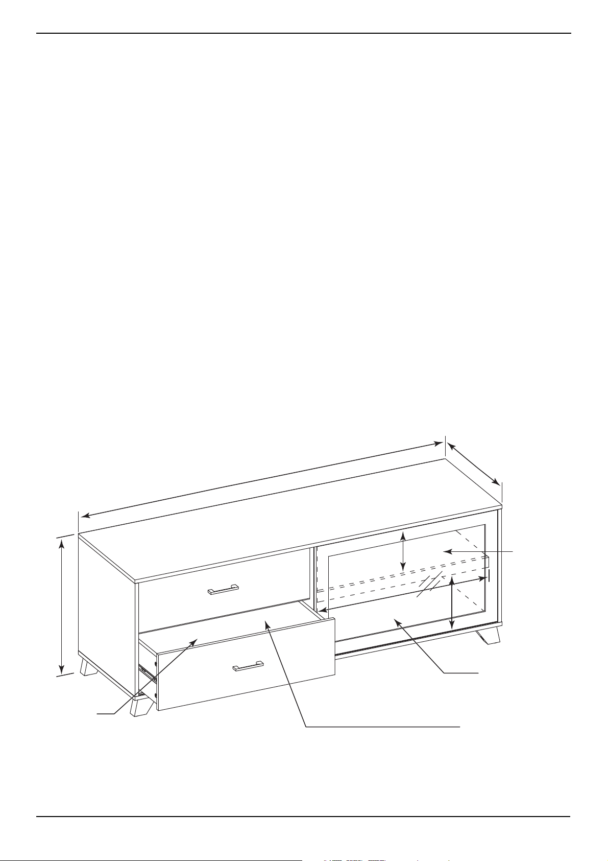
• Supports TVs up to 65" (165.1 cm) and 120 lbs. (54.4 kg)
• Rich dark espresso finish fits your décor
• Two drawers for hiding movies, games, remotes, and more
• Sliding glass door lets you operate AV devices remotely
• Adjustable shelf accommodates most equipment
• Cord cutout provides easy cable routing
NS-HF2003
Dimensions
www.insigniaproducts.com
3
Page 4
Tools needed
Phillips screwdriver
Flathead screwdriver
Rubber mallet
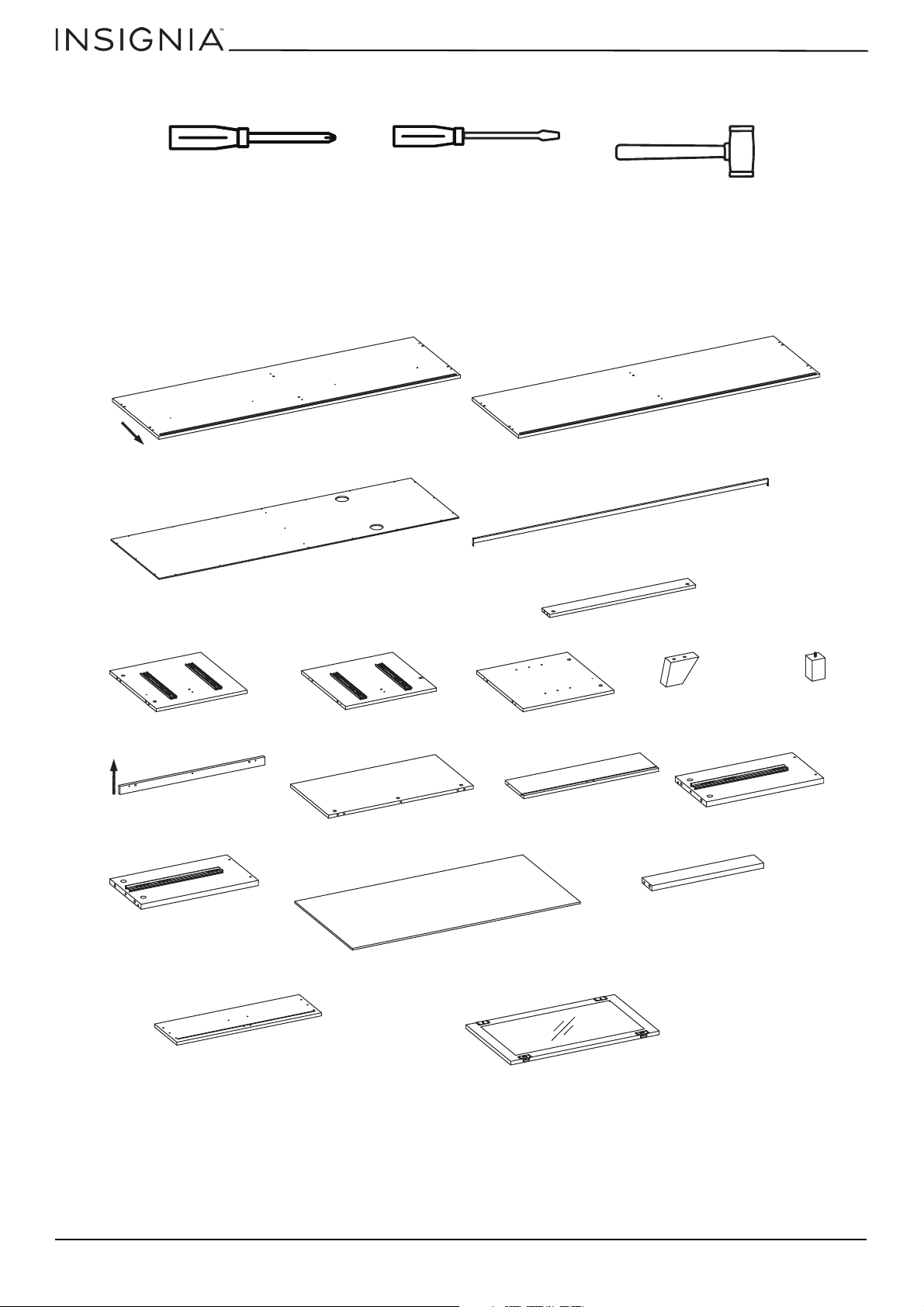
To p
3 Back panel (1)
5 Middle crossbar (1)
2 Bottom panel (1)
1 Top panel (1)
4 Upper crossbar (1)
6 Left side panel (1)
7 Middle panel (1)
8 Right side panel (1)
9 Side
foot (4)
10 Middle
foot (1)
11 Front trim (1)
12 Adjustable shelf (1)
13 Back drawer panel (2)
14 Left drawer panel (2)
15 Right drawer panel (2)
17 Bottom drawer
support (2)
18 Front drawer panel (2)
19 Door (1)
16 Bottom drawer panel (2)
F
r
o
n
t
You need the following tools to assemble your new TV stand:
Package contents
Make sure that you have all the parts and hardware necessary to assemble your new TV stand.
Stand parts
60" Espresso TV Stand
4
www.insigniaproducts.com
Page 5
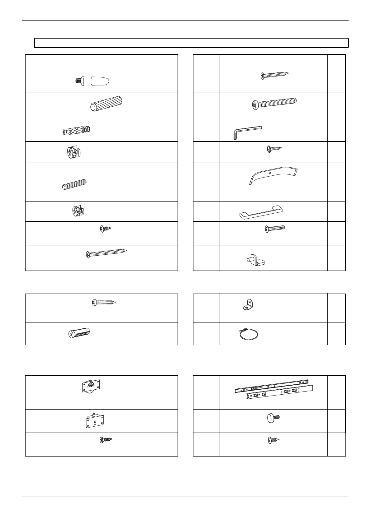
Stand hardware
Glue
Wood screw 4 × 32 × 8 mm (FHWS4328BL)
Large wood dowel (WD830)
Allen bolt 6 × 50 × 10 mm (AB65010BL)
Cam screw (CSST8833BL)
Allen wrench
Large cam lock (CL1512BL)
Wood screw 3 × 16 × 8 mm (RHWS3168BL)
Small wood dowel (WD630)
Wire management strip
Small cam lock (CL1410BL)
Handle
Wood screw 3.5 × 12 × 6 mm (RHWS35126BL)
Machine screw 4 × 21 × 8 mm (MS4218BL)
Wood screw 4 × 50 × 8 mm (FHWS4508BL)
Shelf pin
Wood Screw 4 × 32 × 8 mm (RHWS4328BL)
Mounting tab
Plastic socket
Plastic mounting strap
Roller
Drawer glides (2 pieces per set)
Latch
Floor leveler
Wood screw 3.5 × 12 × 6 mm (FHWS35126BL)
Wood screw 3.5 × 12 × 6 mm (RHWS35126BL)
Note: You may not use all the included hardware.
NS-HF2003
LABEL HARDWARE QTY.
A
B
C
D
E
F
G
1
16
21
11
6
10
2
LABEL HARDWARE QTY.
I
J
K
L
M
N
O
16
8
1
23
2
2
4
H
6
P
Anti-tip safety kit
WA
WB
2
2
WC
WD
Pre-assembled hardware
These parts are pre-assembled and attached to other parts. They are shown here for reference only.
ZA
ZB
2
2
ZD
ZE
4
4
2
4 sets
5
ZC 16 ZF 24
www.insigniaproducts.com
5
Page 6
60" Espresso TV Stand
OR
1/3
OR
Installation tips
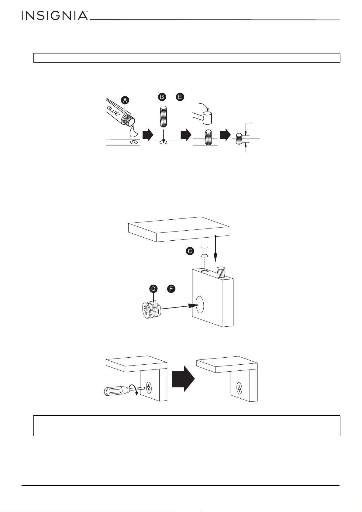
Installing dowels
CAUTION: Make sure that you use glue with the dowels. The glue helps stabilize your TV stand and keeps it from coming apart.
1 Put a drop of glue (A) in the dowel hole, then insert about 2/3 of the dowel (B or E) into the hole. You can tap the dowel
with a rubber mallet, if necessary.
2 After the dowel is installed, wipe off the excess glue with a damp cloth.
Installing cam locks and cam screws
One end of a cam screw (C) is threaded, the other end is not. The un-threaded end locks into a cam lock (D or F).
1 Screw the threaded end of the cam screw (C) into the cam screw hole.
2 Insert a cam lock (D or F) into a cam lock hole. Make sure that the open end in the cam lock faces toward the cam screw
hole.
3 Insert the un-threaded end of a cam screw (C) into the opening in the cam lock.
4 Use a flat blade screwdriver to turn the cam lock clockwise until the arrow and the + and – symbols point away from the
connected panel.
CAUTIONS:
• Do not use an automatic screwdriver to tighten the cam locks.
• Do not over-tighten the cam locks.
6
www.insigniaproducts.com
Page 7
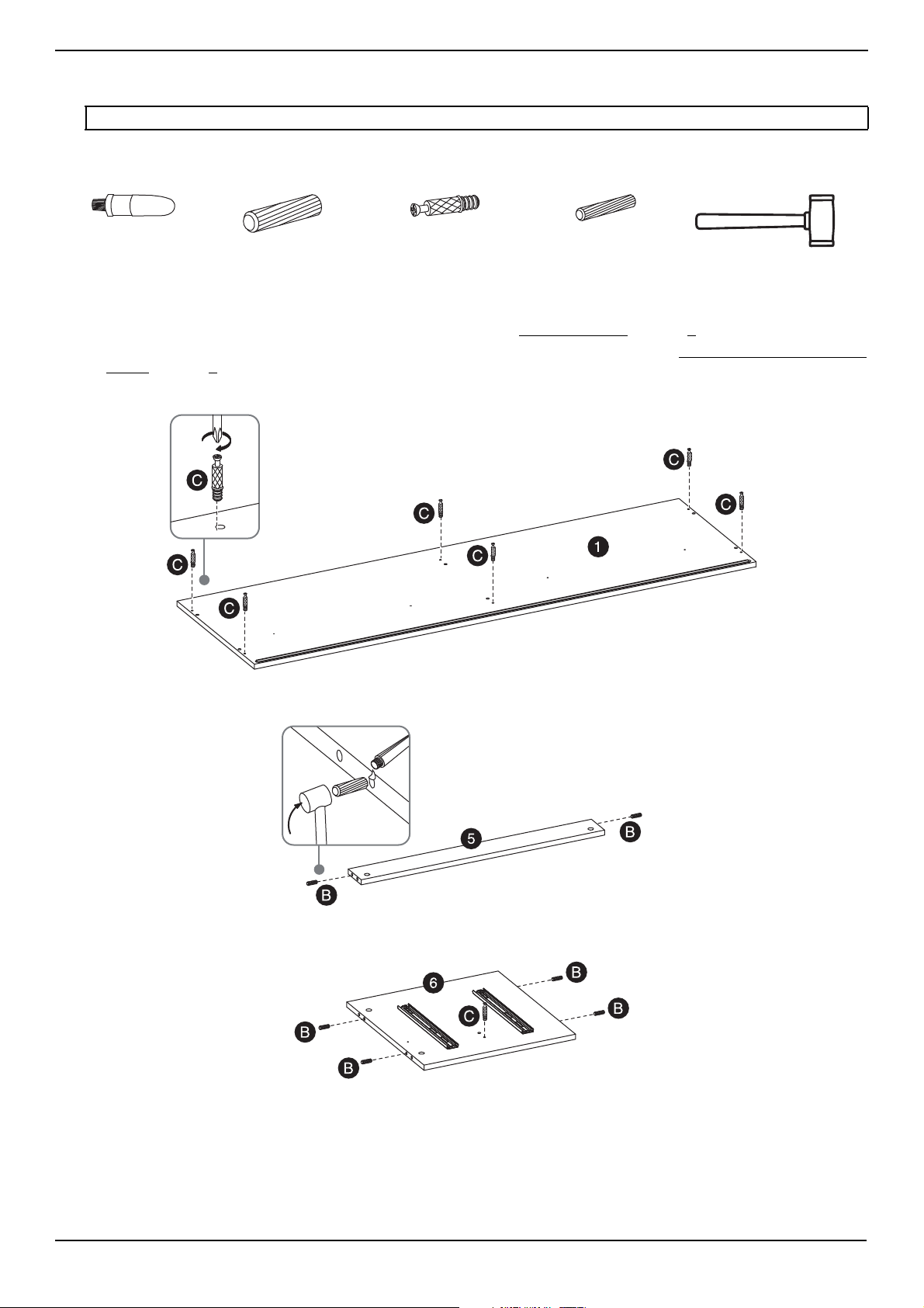
Assembly instructions
A Glue (1)
B Large wood dowel (16)
E Small wood dowel (6)
Rubber mallet
C Cam screw (21)
WAR NIN G: You need two people to assemble your TV stand.
STEP 1 - Install the dowels and cam screws.
You’ll need
1 Put a drop of glue in each dowel hole, then insert about 2/3 of each dowel (B or E) into the hole. Use a rubber mallet, if
needed. Install the dowels (as shown). For more information see Installing dowels
2 Screw the cam screws (C) into the cam screw holes (as shown). For more information, see Installing cam locks and cam
screws on page 6.
Top panel (1)
on page 6.
NS-HF2003
Middle crossbar (5)
Left side panel (6)
www.insigniaproducts.com
7
Page 8

Middle panel (7)
Right side panel (8)
Front trim (11) and adjustable shelf (12)
60" Espresso TV Stand
Left drawer panel (14), right drawer panel (15), bottom drawer support (17), and front drawer panel (18)
Note: You need to insert dowels into two of each part shown.
8
www.insigniaproducts.com
Page 9

STEP 2 - Assemble the left side and middle panels.
Phillips screwdriver
6 Left side panel (1)
7 Middle panel (1)
5 Middle crossbar (1)
4 Upper crossbar (1)
D Large cam lock (2)
G Wood screw 3.5 × 12 × 6 mm
(1)
Flat blade screwdriver
A Glue (1)
You’ll need
1 Insert two large cam locks (D) into the cam lock holes on the ends the middle crossbar (5). Make sure that the openings
on the cam locks face the cam screw holes.
2 Put a drop of glue into each dowel hole on the left side panel (6) and middle panel (7).
3 Insert the dowels and cam screws on the ends of the middle crossbar into the holes in the left side panel and middle
panel.
4 Tighten the cam locks in the middle crossbar.
5 Secure the upper crossbar (4) to the left side panel with one wood screw 3.5 × 12 × 6 mm (G).
NS-HF2003
www.insigniaproducts.com
9
Page 10

60" Espresso TV Stand
2 Bottom panel (1)
A Glue (1)
G Wood screw
3.5 × 12 × 6 mm (1)
H Woo d sc rew
4 × 50 × 8 mm (6)
Phillips screwdriver
Flat blade screwdriver
8 Right side panel (1)
Front
STEP 3 - Attach the right side and bottom panels.
You’ll need
1 Secure the upper crossbar (4) to the right side panel with one wood screw 3.5 × 12 × 6 mm (G).
2 Put a drop of glue into each dowel hole on the left side panel (6), middle panel (7), and right side panel (8).
3 Make sure that the rail on the bottom panel (2) is facing the front of your stand, then insert the dowels on the left,
middle, and right panels into the bottom panel.
4 Secure the bottom panel to the left, middle, and right panels with six wood screws 4 × 50 × 8 mm (H).
10
www.insigniaproducts.com
Page 11

STEP 4 - Attach the feet.
9 Side foot
(4)
J Allen bolt 6 × 50 × 10 mm (8)
K Allen wrench (1)
10 Middle
foot (1)
You’ll need
1 Carefully turn your stand on its side with the bottom panel (2) facing you.
2 Screw the middle foot (10) into the hole in the center of the bottom panel.
3 Align the four side feet (9) with the holes on each corner of the bottom panel. Make sure that the angled sides of the
feet face inward.
4 Insert two Allen bolts 6 × 50 × 10 mm (J) through each foot and the bottom panel and into your stand. Tighten the
screws with the Allen wrench (K).
NS-HF2003
www.insigniaproducts.com
11
Page 12

60" Espresso TV Stand
1 Top panel (1)
D Large cam lock (6)
I Woo d sc rew
4 × 32 × 8 mm (4)
A Glue (1)
Phillips screwdriver
Flat blade screwdriver
F
r
o
n
t
F
r
o
n
t
STEP 5 - Attach the top panel.
You’ll need
1 Carefully turn your stand upright.
2 Insert six large cam locks (D) into the cam lock holes in the left, right, and middle panels. Make sure that the openings
on the cam locks face the cam screw holes.
3 Put a drop of glue in the six dowel holes on the top panel (1).
4 Place the top panel on the left (6), right (8), and middle (7) panels so that the dowels and cam screws align.
5 Tighten the cam locks.
6 Secure the top panel to the upper crossbar (4) with four wood screws 4 × 32 × 8 mm (I)
12
www.insigniaproducts.com
Page 13

STEP 6 - Attach the back panel.
3 Back panel (1)
L Wood screw 3 × 16 × 8 mm
(23)
M Wire management
strip (2)
WC Mounting tabs (2)
Note: WC is part of the
Anti-Tip Safety Kit
Phillips screwdriver
L
WC
WC
You’ll need
1 Align the screws on the back panel (3) with the screw holes on the back of your stand.
2 Align two mounting tabs (WC) with the holes on the top of each corner of the back panel as shown.
3 Insert two wood screws 3 × 16 × 8 mm (L) through the mounting tabs and into the back of your stand. Tighten the
screws.
4 Align two wire management strips (M) horizontally with the center holes on the back panel as shown.
5 Insert two wood screws 3 × 16 × 8 mm (L) through the wire management strips and into the back of your stand. Tighten
the screws.
6 Secure the back panel to your stand with 19 wood screws 3 × 16 × 8 mm (L).
NS-HF2003
www.insigniaproducts.com
13
Page 14

60" Espresso TV Stand
11 Front trim (1)
D Large cam lock (3)
A Glue (1)
Flat blade screwdriver
12 Adjustable shelf (1)
Top
To p
STEP 7 - Attach the trim to the shelf.
You’ll need
1 With the adjustable shelf (12) face down, insert three cam locks (D). Make sure that the openings on the cam locks face
the cam screw holes.
2 Put a drop of glue in the three dowel holes on the front trim (11).
3 Press the shelf and trim together, then tighten the cam locks.
14
www.insigniaproducts.com
Page 15

STEP 8 - Assemble the drawers.
14 Left drawer panel
(2)
15 Right drawer panel
(2)
18 Front drawer panel (2)
A Glue (1)
17 Bottom drawer
support (2)
16 Bottom drawer panel (2)
Assembling the sides, drawer support, and front panels.
You’ll need
1 Place the drawer front (18) face down.
2 Put a drop of glue in the three dowel holes on the front panel.
3 Make sure that the rails on the side panels face out, then align the dowels and cam holes on the left and right side
panels (14 and 15) with the cam screws on the left and right edges of front panel. Press the side panels and front panel
together.
4 Align the dowel on the bottom drawer support (17) with the cam hole in the back edge of the front panel, then press
the parts together.
5 Repeat this step on the other drawer.
NS-HF2003
Attaching the bottom drawer panel.
You’ll need
1 Slide the bottom drawer panel (16) into the grooves on the left drawer panel (14), right drawer panel (15), and front
drawer panel (18).
www.insigniaproducts.com
15
Page 16

2 Repeat this step on the other drawer.
60" Espresso TV Stand
16
www.insigniaproducts.com
Page 17

Attaching the back drawer panels.
13 Back drawer panel (2)
I 4 × 32 × 8 mm screw (12)
Phillips screwdriver
Left
Right
F Small cam lock (10)
Flat blade screwdriver
N Handle (2)
O Machine screw
4 × 21 × 8 mm (4)
You’ll need
1 Align the back drawer panel (13) with the drawer side panels (14 and 15) and bottom drawer support (17).
2 Secure the back drawer panel to the side panels and drawer support using six 4 × 32 × 8 mm screws (I).
3 Insert small cam locks (F) into the cam lock holes on the side panels and drawer support, then tighten the cam locks.
4 Repeat this step on the other drawer.
NS-HF2003
Attaching the drawer handles.
You’ll need
1 Align a handle (N) with the holes in the center of the front drawer panel (18).
2 From the inside of the drawer, secure the handle with two machine screws 4 × 21 × 8 mm (O).
3 Repeat these steps for the other drawer.
www.insigniaproducts.com
17
Page 18

STEP 9 - Insert the drawers and shelf.
Ball bearing
plates
Front
Nylon clip
Front
Nylon clip
Front
Inserting the drawers
1 Slide the ball bearing plates on the left and right drawer side panels to the front of your stand.
2 Align the rails on the drawers with the ball bearing plates, then slide the drawers into your stand.
60" Espresso TV Stand
Removing the drawers
• Pull the drawer out until you can see or feel the black nylon clips on the ball bearing plates, then at the same time, push
the right clip down, the left clip up, and pull the drawer out of your stand.
18
www.insigniaproducts.com
Page 19

Inserting the shelf
P Shelf pin (4)
12 Adjustable shelf (1)
You’ll need
1 Select the level where you want the shelf to sit. You can select from three positions.
2 Insert the four shelf pins (P) into the holes inside your stand. Make sure that the pins are on the same level.
NS-HF2003
3 With the front trim facing you, insert the shelf (12) above the tabs, then lower the shelf onto the tabs.
www.insigniaproducts.com
19
Page 20

60" Espresso TV Stand
19 Door (1)
Phillips screwdriver
The following parts are pre-installed.
ZA Roller ZB Latch
BACK VIEW
Locked
Unlocked
BACK VIEW
STEP 10 - Attach the door.
You’ll need
1 Put the pre-assembled rollers (ZA) on the bottom of the door (19) into the groove on the bottom panel (2).
2 Make sure that the latches (ZB) are unlocked.
3 Insert the latches into the groove on the top of the door (19), then push the latch sliders into the locked position.
4 Make sure that the door slides freely. If the door does not slide freely, loosen the screws in the center of the rollers, turn
the rollers clockwise slightly, then tighten the screws. Test the door movement again.
You’re done! Clean your stand with a damp cloth, then wipe it dry.
20
www.insigniaproducts.com
Page 21

Anti-tip safety strap installation instructions
WA Wood screw
4 × 32 × 8 mm (2)
WB Plastic socket
(2)
WC Mounting
tab (2)
WD Plastic mounting
strap (2)
Phillips screwdriver
Rubber mallet
Note: We recommend that you install the anti-tip strap as a safety precaution.
You’ll need
1 Use a drill with a 5/16" (8 mm) drill bit to drill two holes in your wall approximately two inches below the position of the
mounting tabs on your stand, then insert the plastic sockets (WB) into the holes.
NS-HF2003
Notes:
• You attached the mounting tabs to your stand in STEP 6 - Attach the back panel.
• You can use a rubber mallet to lightly tap the sockets into the holes.
2 Secure the mounting tabs (WC) to the plastic sockets with two of the wood screw 4 × 32 × 8 mm (WA).
3 Thread the plastic mounting straps (WD) through the tabs on your stand and on the wall, then thread the straps
through the strap holes.
4 Pull the straps to tighten them, then thread the straps back through the strap holes to lock them in place.
on page 13.
www.insigniaproducts.com
21
Page 22

60" Espresso TV Stand
ONE-YEAR LIMITED WARRANTY
Definitions:
The Distributor* of Insignia branded products warrants to you, the original purchaser of this new Insignia-branded product (“Product”), that the
Product shall be free of defects in the original manufacturer of the material or workmanship for a period of one (1) year from the date of your purchase
of the Product (“Warranty Period”).
For this warranty to apply, your Product must be purchased in the United States or Canada from a Best Buy branded retail store or online at
www.bestbuy.com or www.bestbuy.ca, and is packaged with this warranty statement.
How long does the coverage last?
The Warranty Period lasts for 1 year (365 days) from the date you purchased the Product. Your purchase date is printed on the receipt you received
with the Product.
What does this warranty cover?
During the Warranty Period, if the original manufacture of the material or workmanship of the Product is determined to be defective by an authorized
Insignia repair center or store personnel, Insignia will (at its sole option): (1) repair the Product with new or rebuilt parts; or (2) replace the Product at
no charge with new or rebuilt comparable products or parts. Products and parts replaced under this warranty become the property of Insignia and are
not returned to you. If service of Products or parts are required after the Warranty Period expires, you must pay all labor and parts charges. This
warranty lasts as long as you own your Insignia Product during the Warranty Period. Warranty coverage terminates if you sell or otherwise transfer the
Product.
How to obtain warranty service?
If you purchased the Product at a Best Buy retail store location, please take your original receipt and the Product to any Best Buy store. Make sure that
you place the Product in its original packaging or packaging that provides the same amount of protection as the original packaging. If you purchased
the Product from a Best Buy online web site (www.bestbuy.com or www.bestbuy.ca), mail your original receipt and the Product to the address listed
on the web site. Make sure that you put the Product in its original packaging or packaging that provides the same amount of protection as the original
packaging.
To obtain warranty service, in the United States call 1-888-BESTBUY, Canada call 1-866-BESTBUY. Call agents may diagnose and correct the issue over
the phone.
Where is the warranty valid?
This warranty is valid only in the United States and Canada at Best Buy branded retail stores or websites to the original purchaser of the product in the
country where the original purchase was made.
What does the warranty not cover?
This warranty does not cover:
• Food loss/spoilage due to failure of refrigerator or freezer
• Customer instruction/education
•Installation
•Set up adjustments
• Cosmetic damage
• Damage due to weather, lightning, and other acts of God, such as power surges
• Accidental damage
•Misuse
•Abuse
•Negligence
• Commercial purposes/use, including but not limited to use in a place of business or in communal areas of a multiple dwelling condominium or
apartment complex, or otherwise used in a place of other than a private home.
• Modification of any part of the Product, including the antenna
• Display panel damaged by static (non-moving) images applied for lengthy periods (burn-in).
• Damage due to incorrect operation or maintenance
• Connection to an incorrect voltage or power supply
• Attempted repair by any person not authorized by Insignia to service the Product
• Products sold “as is” or “with all faults”
• Consumables, including but not limited to batteries (i.e. AA, AAA, C etc.)
• Products where the factory applied serial number has been altered or removed
• Loss or Theft of this product or any part of the product
• Display panels containing up to three (3) pixel failures (dots that are dark or incorrectly illuminated) grouped in an area smaller than one tenth
(1/10) of the display size or up to five (5) pixel failures throughout the display. (Pixel based displays may contain a limited number of pixels that
may not function normally.)
• Failures or Damage caused by any contact including but not limited to liquids, gels or pastes.
REPAIR REPLACEMENT AS PROVIDED UNDER THIS WARRANTY IS YOUR EXCLUSIVE REMEDY FOR BREACH OF WARRANTY. INSIGNIA SHALL NOT BE
LIABLE FOR ANY INCIDENTAL OR CONSEQUENTIAL DAMAGES FOR THE BREACH OF ANY EXPRESS OR IMPLIED WARRANTY ON THIS PRODUCT,
INCLUDING, BUT NOT LIMITED TO, LOST DATA, LOSS OF USE OF YOUR PRODUCT, LOST BUSINESS OR LOST PROFITS. INSIGNIA PRODUCTS MAKES NO
OTHER EXPRESS WARRANTIES WITH RESPECT TO THE PRODUCT, ALL EXPRESS AND IMPLIED WARRANTIES FOR THE PRODUCT, INCLUDING, BUT NOT
LIMITED TO, ANY IMPLIED WARRANTIES OF AND CONDITIONS OF MERCHANTABILITY AND FITNESS FOR A PARTICULAR PURPOSE, ARE LIMITED IN
DURATION TO THE WARRANTY PERIOD SET FORTH ABOVE AND NO WARRANTIES, WHETHER EXPRESS OR IMPLIED, WILL APPLY AFTER THE WARRANTY
PERIOD. SOME STATES, PROVINCES AND JURISDICTIONS DO NOT ALLOW LIMITATIONS ON HOW LONG AN IMPLIED WARRANTY LASTS, SO THE ABOVE
LIMITATION MAY NOT APPLY TO YOU. THIS WARRANTY GIVES YOU SPECIFIC LEGAL RIGHTS, AND YOU MAY ALSO HAVE OTHER RIGHTS, WHICH VARY
FROM STATE TO STATE OR PROVINCE TO PROVINCE.
Contact Insignia:
For customer service please call 1-877-467-4289
www.insigniaproducts.com
INSIGNIA is a trademark of Best Buy and its affiliated companies.
Distributed by Best Buy Purchasing, LLC
7601 Penn Ave South, Richfield, MN 55423 U.S.A.
©2019 Best Buy. All rights reserved.
22
www.insigniaproducts.com
Page 23

For product inquiries, please contact us with the information below:
1-877-467-4289
www.insigniaproducts.com
INSIGNIA is a trademark of Best Buy and its affiliated companies.
Distributed by Best Buy Purchasing, LLC
7601 Penn Ave South, Richfield, MN 55423 U.S.A.
©2019 Best Buy. All rights reserved.
V2 ENGLISH
19-0611
 Loading...