

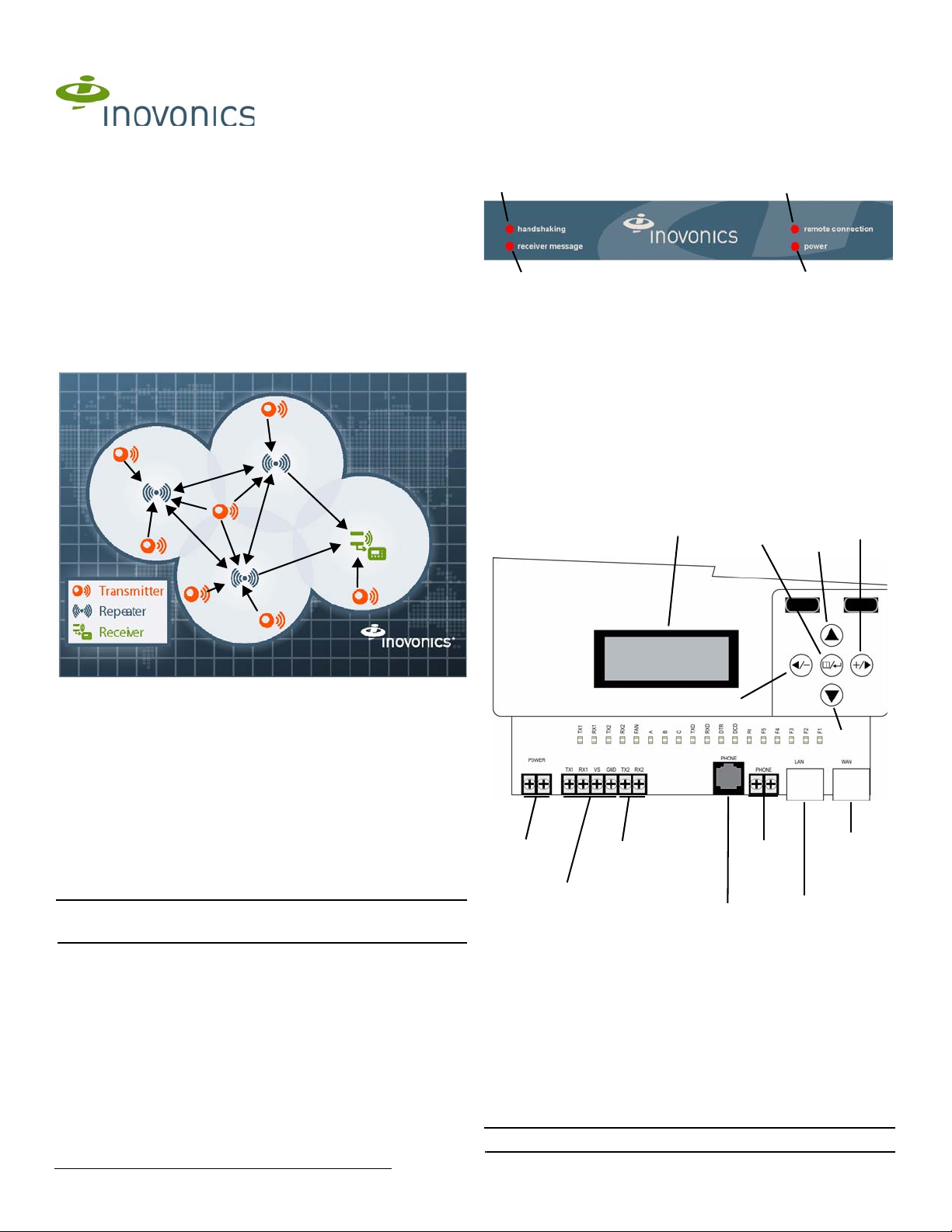
RDL8500 Remote Data Logger
A
B
D
C
Power
terminals
Diagnostics
LAN port
WAN
port
Second
gateway
serial
terminal
First
gateway
serial
terminal
LCD
display
Up
Down
Back
Enter
Advance
Modem
terminals
Diagnostics
RJ11 jack
Installation Instructions
1 Introduction
The RDL8500 remote data logger is installed at a submetering site’s head
end location to collect data from transmitters using the EN4000, EN6540,
and/or FA403 RF gateways. The RDL8500 can remotely communicate with
the billing service or with an onsite technician using the TapWatch.com
website or the Inovonics TapWatch 3 software.
1.1 Installing an Inovonics Submetering System
An EchoStream survey kit should be used to establish an EchoStream
system. The EchoStream survey kit measures the signal strength of highpower repeater and sensor messages to help optimize your EchoStream
system.
1.3 RDL8500 Remote Data Logger Front Panel
Figure 2 RDL8500 remote data logger front panel
A handshaking B receiver
message
C remote
connection
D power
Operation LEDs
handshaking: If using TapWatch.com, this is lit when the RDL8500 is
initializing connection to the website; if using TapWatch 3, this is lit when
the RDL8500 modem is initializing connection to the billing service.
receiver message: Lights when a serial data message is received from the
gateway.
remote connection: If using TapWatch.com, this is lit when the RDL8500 is
connected to TapWatch.com; if using TapWatch 3, this is lit when the
modem is connected to the customer’s billing service.
power: Lit when the RDL8500 is receiving power.
1.4 RDL8500 Internal Components
Figure 1 Sample EchoStream system
The EchoStream survey kit provides you with two signal strength
measurements: signal level and signal margin.
Signal level
The signal level is the measurement of the overall decibel level of the
message.
Signal margin
The signal margin is the measurement of the decibel level of the message,
minus the decibel level of any interfering signals. Inovonics equipment
should be placed within a facility such that all end-devices produce signal
margin readings of at least 4 decibels.
Both the signal level and signal margin are measured in decibels. Because
signal strength and signal margin are measured on a logarithmic scale, the
difference between a decibel level of 3 (Weak) and a decibel level of 4
(Good) is a much larger difference than it would be on a linear scale.
Note: For more information about the EchoStream survey kit, see the
EN7016SK EchoStream® Survey Kit Installation and Operation Manual.
1.2 Inovonics Contact Information
If you have any problems with this installation, contact Inovonics technical
support:
• E-mail: support@inovonics.com
• Phone: (800) 782-2709
5.29.13 05456G © Inovonics, 2013 - www.inovonics.com
Figure 3 RDL8500 internal components
Internal LEDs
TX1: Lit when transmitting data to the first gateway.
RX1: Lit when receiving data from the first gateway.
TX2: Lit when transmitting data to the second gateway.
RX2: Lit when receiving data from the second gateway.
FAN: Lit when the fan is running.
TXD: Lit when the modem is transmitting data.
RXD: Lit when the modem is receiving data.
DTR: Lit when the modem is ready.
DCD: Lit when the modem is connected.
RI: Lit when the modem is ringing.
Note: The rest of the LEDs are reserved.
1.5 What’s In The Carton
RDL8500
EN4000
Vs
GND
TX1/2
RX1/2
Vs
GND
RX
TX
RDL8500
EN6540
Vs
GND
TX1/2
RX1/2
Vs
GND
SER IN
SER OUT
RDL8500
FA403
Vs
GND
TX1/2
RX1/2
Vs
GND
IN
OUT
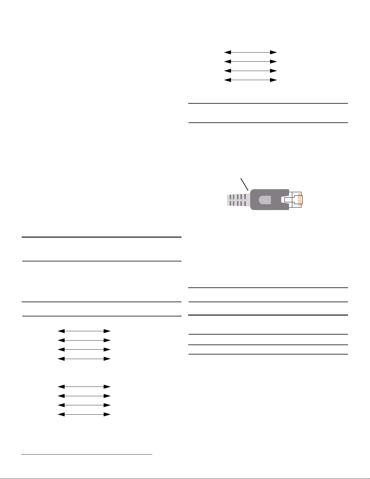
Remove Strain
Relief Boot
• Two drywall anchors
• Two mounting screws
• One power transformer mounting cable tie
• One power transformer mounting screw
• One power transformer
• One six-foot power cable
2 Installation and Startup
2.1 Installation Notes
• These products are designed to be maintained by authorized
TapWatch service providers
• Products are tested for indoor use, non-condensing environment
• The RDL8500 must be mounted within 50 feet of where you plan to
mount the gateway, in a location near a standard 120 VAC wall outlet
• The RDL8500 and RF gatways should be mounted in a location
removed from other electrical equipment
• If you are planning to use TapWatch 3, the RDL8500 must be
mounted within 50 feet of a phone line
• If you are planning to use TapWatch.com, the RDL8500 must be
located near an available Ethernet port with access to the internet, as
close to the main router as possible; coordinate with the facility’s IT
representative to ensure an available port; a WiFi router is not
recommended
2.2 Connect the RDL8500 Remote Data Logger to RF
Gateway(s)
The RDL8500 can be connected to an EN4000, EN6540, and/or FA403 in
any of the following configurations:
• An EN4000, EN6540, or FA403 (conventional or enhanced) by itself
• An EN4000 and an FA403
• An EN6540 and an FA403
• An enhanced FA403 and a conventional FA403
Note: This procedure only provides instructions on how to connect the
RDL8500 to the RF gateway. For more information about EN4000,
EN6540, or FA403 installation, see their corresponding installation
instructions.
1. Use a Phillips screwdriver to loosen the housing screw on the bottom of
the RDL8500.
2. Lift the housing up and off of the hinges.
3. Consulting Figure 4, “RDL8500 to EN4000 connections”, Figure 5,
“RDL8500 to EN6540 connections”, or Figure 6, “RDL8500 to FA403
connections”, connect the gateway to the RDL8500 using 4-conductor,
22 gauge, unshielded wire with a maximum length of 50 feet.
Note: RF gateways can be connected to either TX1/RX1 or TX2/RX2. If
only using one gateway, connect the RDL8500 to TX1/RX1.
Figure 6 RDL8500 to FA403 connections
2.3 Connect Power and Ethernet or Modem Cabling
Caution: Telephone, Ethernet, and power connections should be as
mechanically robust as possible, and protected from accidental
disconnection.
4. If you will be using TapWatch.com, connect one end of an unshielded
Cat 5e Ethernet patch cable to the RDL8500 WAN port (Figure 3); if you
will be using TapWatch 3, skip to step 7.
5. Connect the other end of the patch cable to a port on the network with
access to the internet.
6. Some Cat 5e Ethernet patch cables are equipped with a strain relief
boot. If present, remove the strain relief boot to ensure the RDL8500
housing will close properly.
Figure 7 Remove the Cat 5e Ethernet patch cable strain relief boot
7. If using a phone line, connect the phone line from the screw terminals
on a hardwired wall bracket to the terminal blocks on the RDL8500.
• The phone line should be connected to the telephone wall outlet using
the screw terminals. The RJ11 plug-in phone connector is provided for
easy access to the phone line during on-site maintenance.
8. Use the provided power supply and power cable to connect power to
the RDL8500.
• Circuit protection is built into the power supply
• Power leads are reversible
2.4 Mount the RDL8500 Remote Data Logger
9. Using the anchors and screws provided, mount the RDL8500.
Caution: Neither the RF gateway or the RDL8500 should ever be installed
at floor level.
10. Secure the power supply to the outlet with the provided cable tie and
screw.
Caution: Wiring should exit through the back of the RDL8500, be cut to
length, and be stapled neatly to the wall to reduce the possibility of
personal injury or equipment damage.
2.5 Verify Connection to TapWatch.com
Note: If you will be using TapWatch 3, this can be skipped.
Connection to TapWatch.com is verified through the LCD display (Figure
3). The LCD display default screen provides date, time, and the firmware
Figure 4 RDL8500 to EN4000 connections
Figure 5 RDL8500 to EN6540 connections
5.29.13 05456G © Inovonics, 2013 - www.inovonics.com 2
version. To verify connection to TapWatch.com:
11. From the default screen, press the advance button (Figure 3).
12. Use the down button to navigate to “Network Management” and press
the enter button.
13. Use the down button to navigate to “T apwatch.com” and press the enter
button.
14. Ensure the “Stat:” field displays “Connected.”
15. Use the down button to navigate to the “Prb:” field and ensure there is a
“+” before “Ping,” “DNS,” and “HTTPS,” and not an exclamation point.
 Loading...