


Table of Contents
Preface 4
Notice .................................... ...................... ....................... ....................... .............4
Document Part Number .......................................................................................4
Trademarks ........................................................................................................... 4
US Patent Numbers .......................................................... ... .................................4
Technical Services Contact Information ............................................................5
Document Conventions ................... ... ... ... .... .......................................... ... ... ... ....5
Warranty ................................................................................................................ 5
Chapter 1 Radius Overview 7
1.1 About Radius .................... ... .......................................... .... ... ... ... ....................7
1.2 Defining the Radius System ......................................................... .... ... ... ... ....8
1.2.1 Monitored Devices ..............................................................................................8
1.2.2 Device Categories ...............................................................................................8
1.2.3 Alert Devices .......................................................................................................8
1.2.4 Alert Groups ........................................................................................................8
1.2.5 Modes and Actions .............................................................................................9
1.3 Radius Server Components ..........................................................................9
1.3.1 Radius Server ......................................................................................................9
1.3.2 Network Coordinator ..........................................................................................9
1.3.3 High Power Repeater ..........................................................................................9
1.3.4 Wireless End Devices .........................................................................................10
1.3.4.1 Pendant Transmitters ...............................................................................10
1.3.4.2 Universal Transmitters .............................................................................10
1.3.4.3 Specialized Transmitters .........................................................................10
1.3.5 Dialogic® Combined Media Board ................................................................... .10
1.3.6 Two-Way Radio Interface ...................................................................................10
1.3.7 Paging Base Station and Pagers .......................................................................11
Chapter 2 Radius Server Installation and Configuration 12
6.24.13 06325C © Inovonics, 2013 - www.inovonics.com 1

2.1 Radius Server Installation .............................................................................12
2.1.1 Connect to the Radius Server ............................................................................13
2.1.1.1 Connect to the Radius Server via Microsoft® Remote Desktop ..........13
2.1.1.2 Connect to the Radius Server Locally ....................................................13
2.1.2 Configure the Radius Server with a Static IP Address ....................................13
2.1.3 Check for Active License for your Radius System ..........................................14
Chapter 3 Network Coordinator Installation and Configuration 15
3.1 Network Coordinator Installation ..................................................................15
3.1.1 Configure the Network Coordinator ..................................................................16
Chapter 4 High Power Repeater Installation and Configuration 18
4.1 High Power Repeater Installation .................................................................18
4.1.1 Configure Repeaters ...........................................................................................18
Chapter 5 End Device Installation and Configuration 20
5.1 End Device Installation .................... ..............................................................20
5.1.1 Create Category ..................................................................................................20
5.1.2 Pendant Transmitter Installation .......................................................................22
5.1.2.1 Register a Pendant Transmitter ..............................................................22
5.2 Universal Transmitter Installation ............................. .......................... ..........23
5.2.1 Register a Universal Transmitter .......................................................................23
5.3 Specialized and Motion Detector Transmitter Installation .........................24
5.3.1 Register a Specialized or Motion Detector Transmitter .............................. ....24
Chapter 6 Dialogic® D/41JCT-LS Combined Media Board Installation and Configuration 26
6.1 Dialogic® D/41JCT-LS Combined Media Board Installation .......................26
6.1.1 Configure the Dialogic Board ............................................................................26
6.1.2 Set Up a Phone (Voice Call) Alert ......................................................................27
Chapter 7 Two Way Radio Module Installation 29
7.1 Two-Way Radio Module Installation .............................................................29
6.24.13 06325C © Inovonics, 2013 - www.inovonics.com 2

Chapter 8 Pager Installation and Configuration 30
8.1 WaveWare Paging Base Installation ...................... ....................................... 30
8.1.1 Configure the Paging Base ................................................................................30
8.1.2 Configure Apollo Gold Pagers ...........................................................................31
8.1.3 Configure Wall Pagers ........................................................................................32
8.1.3.1 Advanced Wall Pager Configuration Options ........................................34
Chapter 9 Restart Services 35
9.1 Restart Services .............................................................................................35
6.24.13 06325C © Inovonics, 2013 - www.inovonics.com 3

Preface
Notice
© Inovonics, 2013
Inovonics intends this manual for use by Inovonics customers only. All
comments concerning the contents of this manual should be directed to the
Inovonics marketing department. No part of this work covered by copyright
may be reproduced in any form either graphically, electronically, or
mechanically; including photocopying, recording, taping, or storing in an
information retrieval system without prior written permission from Inovonics.
Document Part Number
06325C
Trademarks
Inovonics, EchoStream, and Radius are registered trademarks of Inovonics.
All other brand names and product names used in this manual are trademarks,
registered trademarks, or trade names of their respective holders.
US Patent Numbers
• 7,154,866
• 7,554,932
• 7,746,804
6.24.13 06325C © Inovonics, 2013 - www.inovonics.com 4

Technical Services Contact Information
For Inovonics technical services:
• E-mail: support@inovonics.com
• Phone: (800) 782-2709; (303) 939-9336
Document Conventions
The following notices are used throughout this document:
Note: Emphasizes points, provides supplementary information, or indicates minor
problems in an expected outcome.
Caution: Indicates possible damage to equipment or loss of data, as well as potential
problems in an expected outcome.
Warning: Indicates the possibility of minor injury to oneself or others.
Danger:Indicates the possibility of serious or fatal injury to oneself or others.
Warranty
Inovonics Wireless Corporation ("Inovonics") warrants the Radius server
hardware to conform to its own specifications and to be free of defects in
materials and workmanship under normal use for a period of twelve (12)
months from the date of manufacture. Within the warranty period, Inovonics
will repair or replace, at its option, all or any part of the warranted product.
Inovonics will not be responsible for dismantling and/or reinstallation charges.
To exercise the warranty, the User ("User", "Installer" or "Consumer") must
work directly through their authorized distributor who will be given a Return
Material Authorization ("RMA") Number by Inovonics. Details of shipment will
be arranged directly through the authorized distributor.
6.24.13 06325C © Inovonics, 2013 - www.inovonics.com 5

This warranty is void in cases of improper installation, misuse, failure to follow
installation and operating instructions, unauthorized alteration, accident or
tampering, and repair by anyone other than Inovonics.
This warranty is exclusive and expressly in lieu of all other warranties,
obligations or liabilities, whether written, oral, express, or implied. There is no
warranty by Inovonics that Inovonics product will be merchantable or fit for any
particular purpose, nor is there any other warranty, expressed or implied,
except as such is expressly set forth herein. In no event shall Inovonics be
liable for an incidental, consequential, indirect, special, or exemplary
damages, including but not limited to loss of profit, revenue or contract, loss of
use, cost of down time, or interruption of business, nor any claim made by
distributor's customers or any other person or entity.
This warranty will not be modified or extended. Inovonics does not authorize
any person to act on its behalf to modify or extend this warranty. This warranty
will apply only to the Radius server hardware. Inovonics will not be liable for
any direct, incidental or consequential damage or loss whatsoever, caused by
the malfunction of product due to products, accessories, or attachments of
other manufacturers, including batteries, used in conjunction with Inovonics
products.
6.24.13 06325C © Inovonics, 2013 - www.inovonics.com 6
Chapter 1
Radius Overview
1.1 About Radius
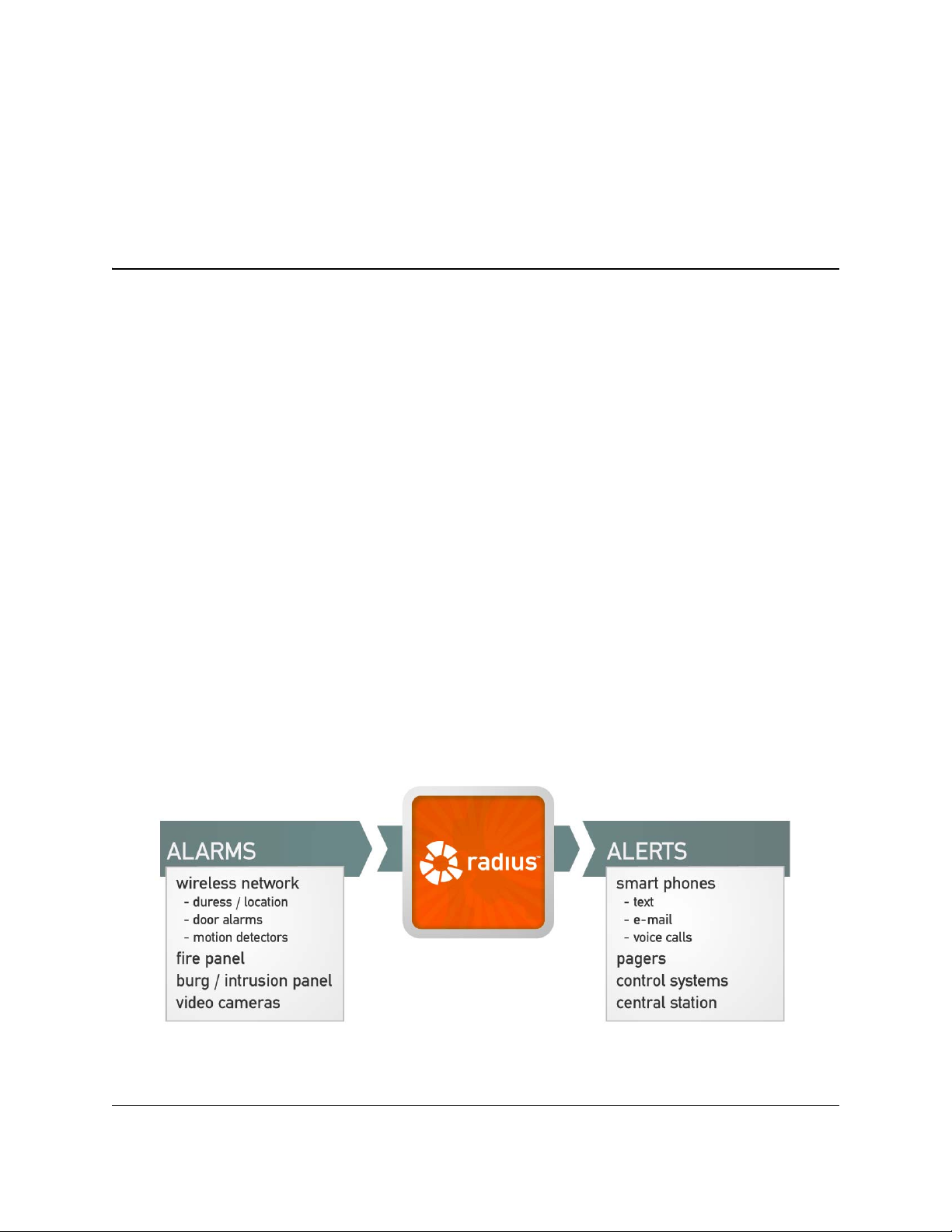
Radius is a revolutionary alert server and awareness engine. Designed to link
people to events in life-safety situations, Radius combines the latest mass
notification capabilities with advanced positioning technology to provide
detailed location information.
Radius provides the central nervous system for your Physical Security
Information Management system. The system integrates data from traditional
security devices, even IP-enabling legacy security and fire panels to do so,
and then coordinates an appropriate response. The location functionality
provided by Inovonics® Positioning Technology™ then ensures those alarms
can be located, so that the response can be effective.
Radius allows users to monitor a variety of end-devices; interface to fire,
access control, and environmental systems; and provide notification to mobile
devices such as cell phones, pagers, and two-way radios.
Figure 1-1 Radius Overview
6.24.13 06325C © Inovonics, 2013 - www.inovonics.com 7

1.2 Defining the Radius System
Every Radius system will differ depending on the specific application, but they
all have in common that they must turn alarms from end devices into alerts
delivered to the user.
Generally, Radius system components are defined as follows:
1.2.1 Monitored Devices
Every device that you are watching for an alarm must be defined as a
monitored device. This includes universal transmitters, pendants, door alarms,
smoke detectors, and motion detectors.
1.2.2 Device Categories
Every monitored device must belong to a category. If you are using motion
detectors, you will need a motion detector category; if you are using pendants,
you need a pendant category. It is in the device category section that you
determine what you want Radius to do when an alarm occurs at a monitored
device.
Radius Overview
1.2.3 Alert Devices
Every device that will receive an alert from Radius must be defined here,
including pagers, phones, and email addresses.
• Any device to which you want to send a quick message or reminder must
be set up in alert devices.
• Any device that you want included in an alarm escalation under modes
and actions must be set up in alert devices.
• If you want to put together an alert group, all members of the group must
be set up in alert devices.
1.2.4 Alert Groups
This feature allows you to create groups of alert devices that will always be
contacted together. Alert groups are especially useful in situations where you
wish to contact a large group of people; by creating an alert group, you only
have to choose a single entry to send a quick message or reminder.
• If you want to put together an alert group, all members of the group must
be set up in alert devices.
6.24.13 06325C © Inovonics, 2013 - www.inovonics.com 8

1.2.5 Modes and Actions
Alarms can be escalated using the modes and actions option. This will allow
you to set up time schedules (modes) and specific alarm responses (actions)
for each device category.
1.3 Radius Server Components
1.3.1 Radius Server
The Radius server is a Windows XP embedded server typically connected to
the local area network (LAN) to allow existing users to view and administer the
Radius system on their workstations.
The Radius server includes four serial ports, one Ethernet port, six USB ports
and four analog telephone jacks.
Radius Overview
• The Radius server requires 110VAC power with an uninterrupted power
supply and an ethernet connection.
1.3.2 Network Coordinator
The network coordinator manages signals between the wireless end devices
in the Radius system and the Radius server.
• The network coordinator requires 110VAC power.
• Generally speaking, the network coordinator should be mounted in an
elevated position, away from metal.
• The network coordinator should be mounted no more than 25 feet away
from the Radius server.
1.3.3 High Power Repeater
The high power repeater intelligently amplifies transmissions from any
Inovonics EchoStream end device, while ignoring background noise. Virtually
any number of repeaters can be added to a system, scaling the system size as
needed.
• The high power repeater requires 110VAC power.
Radius can also use the high power repeater network to provide the
approximate location of wireless end devices sending alert signals.
6.24.13 06325C © Inovonics, 2013 - www.inovonics.com 9

Radius Overview
1.3.4 Wireless End Devices
The Radius system can incorporate any Inovonics wireless end device,
including:
1.3.4.1 Pendant Transmitters
Inovonics wireless pendant transmitters offer virtually limitless opportunities for
panic/duress, life safety, and many custom applications.
• http://www.inovonics.com/pendant-transmitters.aspx
1.3.4.2 Universal Transmitters
Inovonics universal transmitters are designed for use with almost any standard
contact or sensor. They are available in a number of configurations for almost
any application.
• http://www.inovonics.com/universal-transmitters.aspx
1.3.4.3 Specialized Transmitters
Inovonics specialized transmitters are used for unique security, pulse
counting, temperature, and custom applications.
• http://www.inovonics.com/specialized-transmitter.aspx
1.3.5 Dialogic® Combined Media Board
A dialogic combined media board allows the Radius system to make and
receive phone calls. A voice-enabled Radius server includes one four-port
Dialogic board installed.
• The Dialogic combined media board can only be used with a standard
analog phone line. The combined media board will not work with a digital
phone line.
1.3.6 Two-Way Radio Interface
A two-way radio can be connected to the Radius server using a radio interface
box with a phone connection on one end and a 2.5mm jack to interface to a
base radio. The radio interface box will use one of the RJ1 1 jacks found on the
dialogic board.
6.24.13 06325C © Inovonics, 2013 - www.inovonics.com 10

Radius Overview
1.3.7 Paging Base Station and Pagers
The Radius server can connect to a paging base station via one of the serial
ports to deliver POCSAG compliant messages to pagers.
• The paging base station requires 110VAC power.
• Generally speaking, the paging base station should be mounted in an
elevated position, away from metal.
• The paging base station should be mounted no more than 25 feet away
from the Radius server.
6.24.13 06325C © Inovonics, 2013 - www.inovonics.com 11

Chapter 2
Radius Server Installation and Configuration
2.1 Radius Server Installation
To install the Radius server:
1 Use the included mounting hardware to mount the server in a safe,
temperature controlled location.
Caution: The Radius server is equipped with an active temperature monitoring system.
To ensure proper operation of the Radius server, please ensure that the
ambient temperature not exceed 100 degrees farhenheit.
2 Connect UPS battery backup and power.
Caution: The server must be connected to a UPS battery backup to prevent damage
from inadvertant power sources.
3 If desired, connect the server to the LAN using a standard CAT 5 ethernet
cable.
Note: For more information, see “Connect to the Radius Server via Microsoft® Remote
Desktop” on page 13.
4 If desired, connect the server to a local monitor, keyboard, and mouse.
5 Power on the Radius server.
6.24.13 06325C © Inovonics, 2013 - www.inovonics.com 12

Radius Server Installation and Configuration
2.1.1 Connect to the Radius Server
2.1.1.1 Connect to the Radius Server via Microsoft® Remote Desktop
If the Radius server has been connected to the LAN, you can access the
Radius server using Remote Desktop on any desktop running Windows® XP
or Vista.
Note: To access the Radius server you must have the IP address of the server.
1 Click “Start.”
2 Click “Run.”
3 Type in “mstsc” and click “OK.”
4 Enter the IP address of the Radius server and click Connect.
5 Once connected, enter the Radius user name and password provided to
you by Inovonics. If you do not have this information, please call
Inovonics technical services at 800.782.2709, option 2.
6 You should now be connected to the Radius system.
2.1.1.2 Connect to the Radius Server Locally
If the Radius server has been connected to a monitor, keyboard, and mouse
you can connect to the Radius system locally.
1 Power on the Radius server.
2 Once you are in the Windows operating system, double click the Radius
icon on the desktop. By default, this will load the Radius interface login
screen.
3 Enter the Radius user name and password provided to you by Inovonics.
If you do not have this information, please call Inovonics technical
services at 800.782.2709, option 2.
2.1.2 Configure the Radius Server with a Static IP Address
An internet connection is required for the Radius server , and the Radius server
must be assigned a static IP address.
To configure Radius with a static IP address:
1 Contact your local IT administrator to obtain an IP configuration for the
Radius system. You will need the following information:
6.24.13 06325C © Inovonics, 2013 - www.inovonics.com 13

Radius Server Installation and Configuration
• The static IP address
• The default gateway
• Subnet mask
• The address of the DNS server(s)
2.1.3 Check for Active License for your Radius System
You may need to contact Inovonics to obtain an active license for your Radius
system. To determine if you have an active license:
1 Click “Start.”
2 Click “Run.”
3 Type in “cmd” and tap the enter button.
4 Type in “cd\statsol” and tap the enter button.
5 Type in “statlicense.”
6 If you receive a message stating “License file is invalid or missing,” call
Inovonics technical services at 800.782.2709, option 2.
6.24.13 06325C © Inovonics, 2013 - www.inovonics.com 14

Chapter 3
Network Coordinator Installation and Configuration
3.1 Network Coordinator Installation
The network coordinator manages the wireless signals between Inovonics end
devices, high power repeaters, and the Radius server.
To install the network coordinator:
1 Mount the network coordinator per the network coordinator’s installation
instructions.
• Generally, it’s best to mount the network coordinator in an elevated
position, away from metal.
2 Plug the network coordinator’s power cable into a surge protector.
Caution: It is highly recommended that the network coordinator be plugged into a UPS
battery backup.
3 Plug the network coordinator’s data and power cable into COM 1 on the
Radius server.
• The COM port settings for the Radius process creation are 9600/8/1/N.
The port settings are set by default.
6.24.13 06325C © Inovonics, 2013 - www.inovonics.com 15

Network Coordinator Installation and Configuration
3.1.1 Configure the Network Coordinator
Note: This procedure is typically performed at Inovonics before shipping.
To configure the network coordinator:
1 Access the Radius interface and log in.
2 Click “Install Setup.”
3 Click on “Process Setup.”
4 Choose “Serial Alarm” from the “Interface Name” dropdown menu.
5 Click “Add New Interface.”
6 Enter an “Interface Name.”
• Be sure to name the interface something that you and your customer will
recognize. Any device that enters the Radius system through this process
will be given a System ID “processname_xxxxx.”
• We recommended that the process name be only one word, such as
“coordinator.”
7 Check the box for “Start Interface when Services Start.”
8 Check the box for “Automatically Create New Devices.”
• You will only want this checked during installation. Once you’ve
completed installation, return to this screen and uncheck it to ensure
devices in neighboring systems don’t impact your system.
9 Set the “Debug Level:” to “None.”
10 Select “Inovonics EchoStream” from the “Serial Interface Type.”
11 Enter a NID for the system in the “EchoStream Network ID” field. Any
number, 1-31, will work.
12 If you will be immediately registering repeaters, check the box for “Add
new Echostream repeaters to NID when Reset button pressed.”
Note: You will only want this checked during installation. Once you’ve completed
installation, return to this screen and uncheck it to ensure devices in neighboring
systems don’t impact your system.
13 Set the “Minimum Activity Interval” to “3.”
6.24.13 06325C © Inovonics, 2013 - www.inovonics.com 16

Network Coordinator Installation and Configuration
• This setting monitors the data flow of the Radius system. If no data enters
the Radius system during a three minute interval, Radius will create and
log an error . If the site is under a NOC agreement and the server is set to
report to the NOC, Inovonics will be notified of errors.
14 Set the COM settings under “Selection connection Type” to “Direct Serial”
and enter “COM1.”
15 Click “Insert.”
16 Restart services.
• For more information about restarting services, see “Restart Services” on
page 35.
6.24.13 06325C © Inovonics, 2013 - www.inovonics.com 17

Chapter 4
High Power Repeater Installation and Configuration
4.1 High Power Repeater Installation
The Inovonics high power repeater intelligently amplifies transmission from
any EchoStream series end device while ignoring background noise. Virtually
any number of repeaters can be added to a system, scaling the system size as
needed.
• For installation instructions and more information: http://
www.inovonics.com/high-power-repeater.aspx
Repeaters will automatically be discovered in the Radius system during the
installation process, but not yet enrolled.
4.1.1 Configure Repeaters
In a Radius system, repeaters are also used to determine the location of end
devices in alarm. The minimum signal strength can be adjusted to fine-tune
the repeater’s location capability. The higher you set the minimum signal
strength, the closer the device in alarm must be to the repeater for the location
to be determined. For example, setting a minimum signal strength of ten dB
will only report location information for alarms with a signal strength of higher
than ten dB.
To adjust the minimum signal strength:
1 Access the Radius interface and log in.
2 Click “Install Setup.”
3 Click on “Process Setup.”
6.24.13 06325C © Inovonics, 2013 - www.inovonics.com 18

High Power Repeater Installation and Configuration
4 Select the EN6040 network coordinator.
5 Check the box for “Add new Echostream repeaters to NID when Reset
button pressed.”
6 Click “Administration.”
7 Click “Monitored Devices.”
8 Select “Repeaters and Locators” from the drop down menu.
9 Click the name of the repeater in the “Device Description” field.
10 Enter a description in the “Monitored Device Description.”
• The text entered here is what will be displayed on the main screen and in
reports.
11 As desired, enter any notes in the “Notes” field.
12 As desired, set a minimum signal strength for the purposes of location in
the “Minimum signal strength for location (0-100).”
13 Click “Update Monitored Device.”
6.24.13 06325C © Inovonics, 2013 - www.inovonics.com 19

Chapter 5
End Device Installation and Configuration
5.1 End Device Installation
Inovonics end devices typically fall under four categories:
• Pendant transmitters
• Universal transmitters
• Motion detector transmitters
• Specialized transmitters
Although the installation of all of the above is similar, there are some
differences.
5.1.1 Create Category
End devices enrolled into the Radius system must be added to a device
category before they can be used. In some cases you will need to create the
device category to which you will add the end device. End devices that will
need a device category created for them include:
• Door alarm transmitters
• Universal transmitters
• Smoke detectors
• Motion detectors
To check current device categories and create new ones:
1 From the home screen, click “Administration.”
2 Click “Device Categories.”
6.24.13 06325C © Inovonics, 2013 - www.inovonics.com 20

End Device Installation and Configuration
3 If you do not see the category needed for the end device you’re enrolling,
click “Create a New Category.”
4 In the “Description Field,” enter a description of the device category.
5 In the “Missing Interval” field, enter the time, in minutes, to elapse
between check in messages before a device in this category will be
considered missing.
6 Check the box next to “Do not show devices in this category on the main
status screen” if you want to keep end devices in this category from
displaying on the main screen.
• This can be useful for devices which will only be used used to establish
the vector map necessary for location functionality.
7 If this category will contain pendants, and you want them to be locatable,
check the box for “This category contains pendants - collect location
information.”
8 Edit the “Message for active alarms” field as desired to customize alarm
messages sent for devices in this category. If left blank, the default alarm
message will be used.
• Use the system values in the help pop-up window to include variable
information in your message.
9 Edit the “Message for alarm clears” field as desired to customize alarm
clear messages sent for devices in this category. If left blank, the default
alarm clear message will be used.
• Use the system values in the help pop-up window to include variable
information in your message.
Caution: The Auto Create IDs field is used by Inovonics support personnel. Do not edit
this field with consulting Inovonics technical support.
10 As desired, enter any notes in the “Notes” field.
11 Click “Insert Category”. The new category will now display on the “Device
Categories” screen.
12 Repeat for each category of device you will be using.
6.24.13 06325C © Inovonics, 2013 - www.inovonics.com 21

End Device Installation and Configuration
5.1.2 Pendant Transmitter Installation
Inovonics pendant transmitters are versatile mobile transmitters that can be
used anywhere within the EchoStream Commercial Mesh Network.
For more about Inovonics pendant transmitters:
• http://www.inovonics.com/pendant-transmitters.aspx
5.1.2.1 Register a Pendant Transmitter
1 From the home screen, click “Administration.”
2 Click “Monitored Devices.”
3 Push the alarm button(s) so that it enrolls in the Radius system. The
device will appear on the monitored devices screen in the “New Devices”
category.
Note: Activating the device is usually the easiest way to add it to “New Devices,” but
any message will suffice, even a tamper or check-in message.
4 Click the name of the device in the “Device Description” field.
• If there is more than one new device, make sure the ID number in the new
device list matches that on the box of the pendant.
5 As desired, enter a “Spoken Device Description.”
• This is only used if the spoken device pronunciation will differ from the
text entered under the “Monitored Device Description.” For example,
because “room number 1414” would be spoken as “room number one
thousand four hundred and fourteen,” this can be written as “room
number fourteen fourteen” so that it will be pronounced correctly . Another
example might be a word with a challenging text-to-speech pronunciation
like “anesthesiology,” which should be spelled phonetically. This change
will not show up on the main screen, reports or pagers; it will only change
the pronunciation as spoken by the system.
6 Select “Pendant” in “Device Category.”
7 If you wish to use the location feature for pendants, you must select the
check box for “This Category contains Pendants – Collect location
information.”
8 If you want the alarm to latch on until reset, check the box for “Use
Pendant reset button.”
6.24.13 06325C © Inovonics, 2013 - www.inovonics.com 22

End Device Installation and Configuration
• This is to ensure that alarm resets are coming from the specific device. It
also inhibits additional alarms until reset.
9 Enter a “Monitored Device Description.”
10 If you want a different alarm message than the default category message,
assign a custom “Alert Message.”
11 Add “Notes” as desired in the available field.
12 Click “Update Monitored Device.”
13 Reset the pendant transmitter per the transmitter’s installation
instructions.
5.2 Universal Transmitter Installation
Inovonics universal transmitters are designed to make nearly any normally
open/normally closed sensor wireless. The universal transmitter should be
installed per the transmitter’s installation instructions.
For more about Inovonics universal transmitters:
• http://www.inovonics.com/universal-transmitters.aspx
5.2.1 Register a Universal Transmitter
1 From the home screen, click “Administration.”
2 Click “Monitored Devices.”
3 Open the universal transmitter housing and press the reset button. The
device will appear on the monitored devices screen in the “New Devices”
category.
4 Click the name of the device in the “Device Description” field.
• If there is more than one new device, make sure the ID number in the new
device list matches that on the box of the universal transmitter.
5 Select desired “Device Category. ”
6 Enter a “Monitored Device Description.”
7 As desired, enter a “Spoken Device Description.”
• This is only used if the spoken device pronunciation will differ from the
text entered under the “Monitored Device Description.” For example,
because “room number 1414” would be spoken as “room number one
thousand four hundred and fourteen,” this can be written as “room
6.24.13 06325C © Inovonics, 2013 - www.inovonics.com 23

End Device Installation and Configuration
number fourteen fourteen” so that it will be pronounced correctly . Another
example might be a word with a challenging text-to-speech pronunciation
like “anesthesiology,” which should be spelled phonetically. This change
will not show up on the main screen, reports or pagers; it will only change
the pronunciation as spoken by the system.
8 Assign a custom “Alert Message” as desired.
9 Add “Notes” as desired in the available field.
10 Click “Update Device Record.”
5.3 Specialized and Motion Detector Transmitter Installation
Inovonics specialized transmitters can be used for unique security applications
including custom designed applications. They include bill trap transmitter,
glassbreak transmitters, and smoke detectors.
For more about specialized transmitters:
• http://www.inovonics.com/specialized-transmitter.aspx
Inovonics motion detectors feature digital signal processing to recognize
human signature movements, reducing false alarms, and can be fully
supervised, include a lithium battery , provide case tamper protection, and have
an attractive design to blend into virtually any environment.
For more about motion detector transmitters:
• http://www.inovonics.com/motion-detectors.aspx
5.3.1 Register a Specialized or Motion Detector Transmitter
11 Click “Administration.”
12 Click “Monitored Devices.”
13 Open the transmitter housing and press the reset button.
14 Click the name of the device in the “Device Description” field.
• If there is more than one new device, make sure the ID number in the new
device list matches that on the box of the universal transmitter.
15 Select desired “Device Category.”
16 Enter a “Monitored Device Description.”
6.24.13 06325C © Inovonics, 2013 - www.inovonics.com 24

End Device Installation and Configuration
17 As desired, enter a “Spoken Device Description.”
• This is only used if the spoken device pronunciation will differ from the
text entered under the “Monitored Device Description.” For example,
because “room number 1414” would be spoken as “room number one
thousand four hundred and fourteen,” this can be written as “room
number fourteen fourteen” so that it will be pronounced correctly . Another
example might be a word with a challenging text-to-speech pronunciation
like “anesthesiology,” which should be spelled phonetically. This change
will not show up on the main screen, reports, or pagers; it will only change
the pronunciation as spoken by the system.
18 Assign a custom “Alert Message” as desired.
19 Add “Notes” as desired in the available field.
20 Click “Update Device Record.”
6.24.13 06325C © Inovonics, 2013 - www.inovonics.com 25

Chapter 6
Dialogic® D/41JCT-LS Combined Media Board Installation and Configuration
6.1 Dialogic® D/41JCT-LS Combined Media Board Installation
The Radius server can support one or more Dialogic combined media boards
to allow the system to make and receive phone calls.
Note: The Dialogic combined media board can only be used with a standard analog
phone line. The combined media board will not work with a digital phone line.
The Radius system can support up to 24 simultaneous phone calls. For more
information, please call Inovonics technical services at 800.782.2709, option
2.
6.1.1 Configure the Dialogic Board
1 Access the Radius interface and log in.
2 Click on “Install Setup.”
3 Click on “Process Setup.”
4 Select the drop down menu and choose “Telephony.”
5 Select “Add New Interface.”
6 Enter a descriptive name in the “Interface Name”.
7 Check the box for “Start Interface when Service Starts.”
6.24.13 06325C © Inovonics, 2013 - www.inovonics.com 26

Dialogic® D/41JCT-LS Combined Media Board Installation and Configuration
8 From the “Interface Type” drop down menu, select “Dialogic”.
9 As desired, check “Only Process Alert Devices Restricted to this
Interface.”
10 From the “Dialogic Channel” drop down menu, select the channel that
corresponds to your phone line.
• Select “Board 1 Channel (Port) 1” for line 1, “Board 1 Channel (Port) 2” for
line 2, etc.
11 As desired, check “Line Has Caller ID.”
12 As desired, check “Monitor inbound calls, but do not answer. (allows
triggering of alarms without answering call)”.
13 As desired, check “Poll Inbound Calls for Integration Digits (i.e.
MainStreet Messanger - requires additional hardware)”.
14 As desired, check “Inbound devices support Contact ID (i.e. Alarm
Panels, but not MSM/Elcombe)”.
15 As desired, enter an IP addres in the “IP Address of Channel Control
Relay” field.
16 Click “Insert.”
17 Restart services.
• For more information about restarting services, see “Restart Services” on
page 35.
6.1.2 Set Up a Phone (Voice Call) A l ert
1 Access the Radius interface and log in.
2 Click on “Administration.”
3 Click “Alert Devices.”
4 Click “Create a New Alert Device.”
5 Select “Phone (Voice Call)” from the “Insert Alert Device” dropdown
menu.
6 Enter a description of the alert device in the “Description” field.
7 If desired, choose an alert device category from the “Alert Device
Category” dropdown menu.
• This is usually used for quick messages and reminders.
6.24.13 06325C © Inovonics, 2013 - www.inovonics.com 27

Dialogic® D/41JCT-LS Combined Media Board Installation and Configuration
8 Enter the telephone number of the device in the “Telephone Number (as it
should be dialed)” field.
Note: Enter the number as it would be dialed from a phone connected to the same line.
For example, if you need to dial a 9 to get an outside line enter the number as
9,1,1234567890, with each comma as a one second pause in the dialing
sequence.
9 If you wish to restrict calls to this number to a particular phone line, select
the line from the drop down menu and check the box next to “Restrict
Calls to This Interface.”
10 As desired, Check the box next to “Retry after leaving a message.”
11 As desired, check the box next to “Retry after no answer.”
• By default the Radius system will allow the phone call attempt to ring for
roughly 30 seconds before hanging up. Once the Radius system hangs
up it will automatically queue the phone call for another attempt according
to the alert device’s settings.
12 As desired, check the box next to “Send notification when alarm is
confirmed.”
13 Set “How many times should the system try to call?”
14 Set “How many minutes should the system wait between call attempts?”
15 As desired add any notes in the “Notes” field.
16 Click “Insert Alert Device.”
6.24.13 06325C © Inovonics, 2013 - www.inovonics.com 28

Chapter 7
Two Way Radio Module Installation
7.1 Two-Way Radio Module Installation
The radio module has a phone connection on one end, and a 2.5mm
microphone plug to interface to a handset.
To install the two-way radio interface box:
1 Plug the radio module’s 2.5mm microphone plug into the handset.
2 Connect a phone cable from a Radius server’s Dialogic port to the radio
module.
3 Connect the power supply to a 110V AC power source.
6.24.13 06325C © Inovonics, 2013 - www.inovonics.com 29

Chapter 8
Pager Installation and Configuration
8.1 WaveWare Paging Base Installation
The WaveWare paging base is a 5 watt paging base station programmed for
469.6500 MHz POCSAG compliant pagers.
To install the WaveWare paging base:
1 Mount the paging base.
• Generally, it’s best to mount the paging base in an elevated position,
away from metal.
• The paging base is shipped with a six foot serial cable. However , the base
station can be mounted up to 20 feet from the Radius server if needed.
2 Attach the supplied antenna to the paging base.
Caution: Do not test the paging base without the antenna attached. Doing so can harm
the paging base.
3 Plug the paging base’s serial cable into COM 2 on the Radius server.
• The COM port settings for the Radius process creation are 9600/8/1/N.
The port settings are set by default.
8.1.1 Configure the Paging Base
1 Access the Radius interface and log in.
2 Click “Install Setup.”
3 Click “Process Setup.”
6.24.13 06325C © Inovonics, 2013 - www.inovonics.com 30

Pager Installation and Configuration
4 Select “Local Paging/LCD Messaging” from the “New Interface Type:”
dropdown menu.
5 Click “Add Interface.”
6 Enter “WaveWare” in the “Interface Name.”
7 Check the box next to “Start Interface when Service Starts.”
8 Select the corresponding pager type from the “Interface T ype:” dropdown
menu. If you do not see the corresponding pager type:
a. Click “Install Setup.”
a. Click “Option Setup.”
b. Check the box next to “Waveware Pager (Fast – Dip Switch 6 Off).”
c. Click “Update.”
• For more information about restarting services, see “Restart Services” on
page 35.
9 Leave the box next to “Only Process Alert Devices Restricted to this
Interface” unchecked.
10 Set the “Minimum Activity Interval” to three minutes
• This setting monitors the data flow of the Radius system. If no data enters
the Radius system during a three minute interval, Radius will create and
log an error.
11 Set the “IP Reconnection Interval” to 60 minutes.
12 Set the COM settings to “Direct Serial” and enter COM2.
13 As desired, enter any notes in the “Notes” field.
14 Click “Insert.”
15 Restart services.
• For more information about restarting services, see “Restart Services” on
page 35.
8.1.2 Configure Apollo Gold Pagers
1 Access the Radius interface and log in.
2 Click “Administration.”
3 Click “Alert Devices.”
4 Click “Create a New Alert Device.”
6.24.13 06325C © Inovonics, 2013 - www.inovonics.com 31

Pager Installation and Configuration
5 Choose “Local Pager” from the “Insert Alert Device” dropdown menu.
6 Click “Add New Alert Device.”
7 Enter a name in the “Description” field.
8 Choose the corresponding “Alert Device Category,” if one applies.
9 Enter the “Pager ID.”
• This is also known as the CAP code, found on the back of the pager.
Note: Each pager is shipped with a global CAP code as well as an individual CAP Code.
The global CAP code can be used to send a message to all pagers on site; the
individual CAP code is used to send a message to that specific pager.
10 As desired, check the box next to “Send notification when alarm is
confirmed”.
11 As desired, check the box next to “Restrict calls to this interface” and
choose the appropriate paging base from the drop down menu.
12 Enter any notes in the “Notes” field.
13 Click “Insert Alert Device.”
14 T est the operation of the p aging base and pager configuration by sending
a quick message to a pager.
8.1.3 Configure Wall Pagers
1 Access the Radius interface and log in.
2 Click “Install Setup.”
3 Click “Option Setup.”
4 Click “Process T ype.”
5 Check the box next to “Wall Board”
6 Click “Update.”
7 Restart services.
• For more information about restarting services, see “Restart Services” on
page 35.
6.24.13 06325C © Inovonics, 2013 - www.inovonics.com 32

Pager Installation and Configuration
Caution: Verify system status, making sure that all processes have restarted, before
continuing.
8 Click “Administration.”
9 Click “Alert Devices.”
10 Click on “Create a New Alert Device.”
11 Select “Wall Pager” from the “Insert Alert Device” drop down menu.
12 Enter a name in the “Description.”
13 Choose the corresponding “Alert Device Category,” if one applies.
14 Enter the “Wall Pager ID.”
• This is also known as the CAP code, and will be included with the
materials received from Inovonics. It will be a five digit number beginning
with 100.
15 As desired, check “Initialize the wall pager with the following values on
startup or modification” to have the optional messages displayed upon
startup or modification.
16 As desired, check “Show time”.
17 As desired, check “Show date”.
18 As desired, check “Annunciate when displaying message”.
19 As desired, check “Show this message when idle”.
20 As desired, check enter an “Annunciate type”.
21 As desired, enter an “Annunciate time”.
22 As desired, check “Show location information for pendant alarms.”
23 As desired, check “Display full alert message”.
24 As desired, check “Send notification when alarm is confirmed.”
25 As desired, check the box next to “Restrict calls to this interface” and
choose the appropriate paging base from the drop down menu.
• Do not select this option unless there is more than one paging base on
site.
26 Set a display time in the “Display time for wallboard quick messages”
field.
27 Enter any notes in the “Notes” field.
6.24.13 06325C © Inovonics, 2013 - www.inovonics.com 33

Pager Installation and Configuration
28 Click “Insert Alert Device.”
29 T est the operation of the p aging base and pager configuration by sending
a quick message to a pager.
30 The alert device type “Wall Pager” will be listed in the alert device menu
and can now be added to actions, as desired.
• You must have a custom alert message programmed for this device to
function properly.
• The wall pager should only be added to each action one time. For
example, if using an escalation path for alerts, include the wall pager only
one time in that action at the first stage.
8.1.3.1 Advanced Wall Pager Configuration Options
The wall pager is controlled by a configuration file that Radius uses to
determine its default settings. The file is located in the C:\St at sol> directory on
each Radius server. The default file name is wall_pager.conf. This file can be
used to customize the way the wall pager behaves and shows certain items on
the display.
The default wall_pager.conf file is overwritten during any software update. To
ensure the file is not overwritten:
1 Create a copy of the existing wall_pager.conf, and name it
wall_pager_site.conf in the Statsol Directory.
• The system will automatically check to see if there is a
wall_pager_site.conf in the statsol directory. If wall_pager_site.conf is
found, it will use this configuration. If wall_pager_site.conf is not found the
system will revert back to the default and use wall_pager.conf.
2 Once you have created the new file, wall_pager_site.conf, edit the
information within that file.
6.24.13 06325C © Inovonics, 2013 - www.inovonics.com 34

Chapter 9
Restart Services
9.1 Restart Services
Restarting services is necessary at multiple points throughout the installation
process.
To restart services:
1 Access the Radius interface and log in.
2 Click “Reports.”
3 Click “System Status.”
4 Check “System Status” for current processes running.
• After restarting services you will return to this screen to ensure the
processes have restarted.
5 Click “Reminders.”
6 Verify that none are scheduled to start within the next 15 minutes.
7 Minimize the browser window.
8 Double-click the “Services” icon on your desktop.
9 Scroll down to “Inovonics Radius Main.”
10 Right click on “Inovonics Radius Main” and select “Restart.”
11 Verify that process have restarted by returning to the “System Status”
screen.
6.24.13 06325C © Inovonics, 2013 - www.inovonics.com 35
 Loading...