

pp
FA130
Frequency Agile£ 900MHz
Wireless Keypad
Installation Instructions
02583B
Attention: The FA130 keypad requires Vision Plus
C2020 V1.4x or greater
or greater.
FA400 receiver firmware V1.5x
and
panel firmware
800-782-2709
For technical support
or a
nThis product is designed to be installed and maintained by
professional security technicians.
nUnless specifically noted, Inovonics products are intended for
indoor use. This receiver is intended for use with indoor
security systems. Use in outdoor applications may impair
performance.
Inovonics Wireless Corporation
E-mail: support@inovonics.com
www.inovonicswireless.com
lication assistance
Important Notes
315 CTC Blvd
Louisville CO 80027
1
2
3
4
5
6
7
8
9
0
FIRE
REVIEW
POLICE
OFF
SPECIAL
CHIME
EMERGENCY
ENTER
STAY
AWAY
CUSTOM
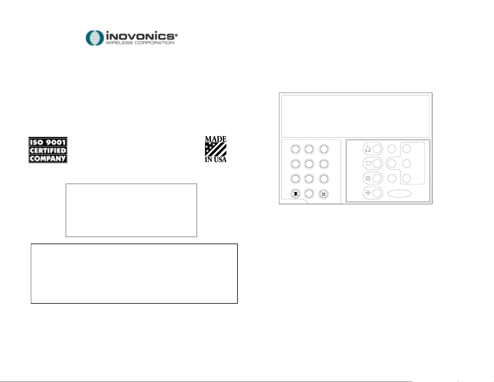
Figure 1: FA130 Keypad
Recommended programming:
Type: KEYPAD
Monitored: No (Not Applicable)
Audible: No (Not Applicable)
Relay out: No (Not Applicable)
Recommended Check-in: 30 seconds*
Typical battery life: 3-4 years
Battery type: BAT604 Duracell DL123A 3V
Low battery monitoring: automatic
* Programmed check-in values are executed at 3-times the interval shown to
extend battery life. For example, " 30 seconds" results in a 90-second checkin interval.
FA130 Keypad
The FA130 keypad is a 900MHz wireless transmitter used to arm and disarm
the Vision Plus™ or Wireless Guardian™ system. The FA130 is a one-way
device, which can be programmed as a supervised point. Functionally, the
FA130 emulates the KP130 hardwire executive keypad, without the LCD
display.
PROGRAMMING THE KEYPAD:
1. If desired, identify the point number of the unit with numbered labels
provided with the Vision Plus™ or Wireless Guardian™ panel.
2. Turn the phillips-head screw on the bottom of the housing slightly.
Separate the housing halves.
3. Complete program data entry as shown below Figure 1. When prompted
to "Plug in Xmitter", connect the programming cable between
programming headers on the hardwire executive keypad and the FA130
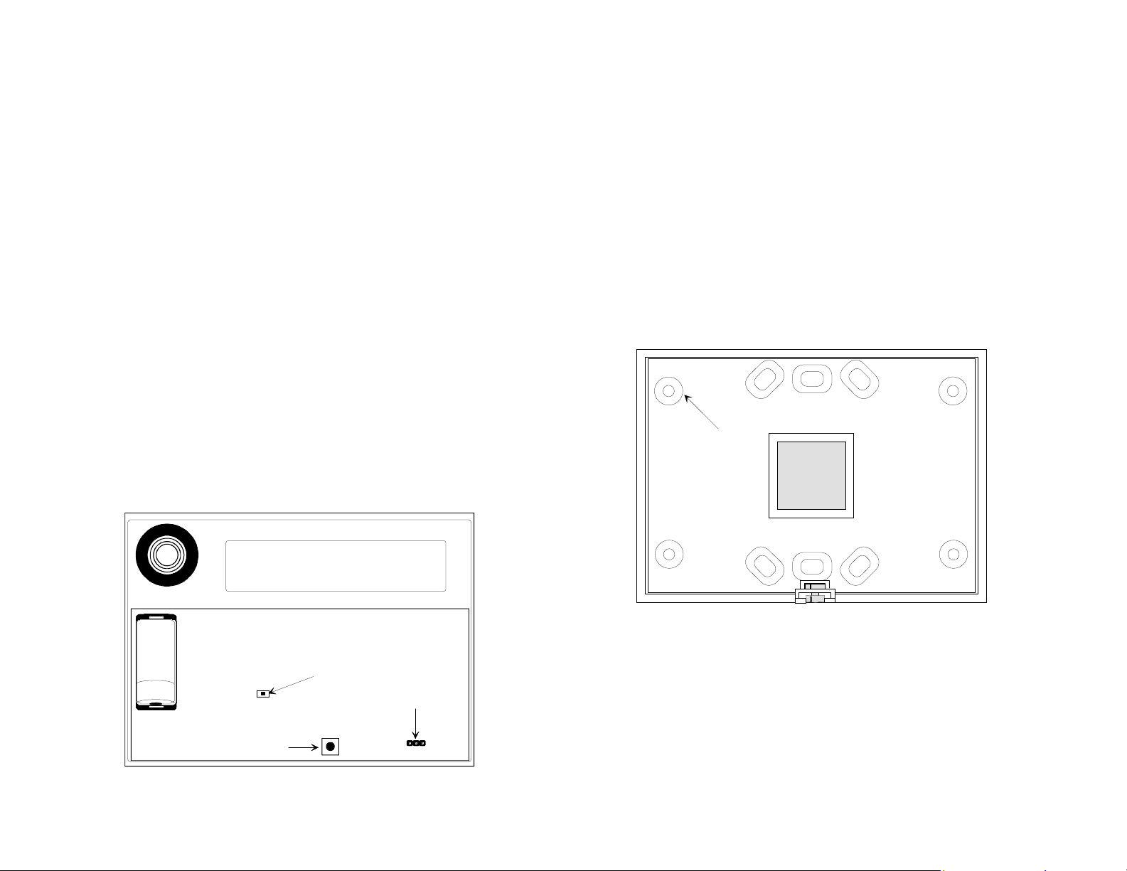
wireless keypad. Refer to Figure 2 to locate the programming header.
4. Press the reset button on the FA130 keypad. When programming has
been confirmed by the hardwire executive keypad, disconnect the
programming cable.
5. Test the FA130. Pressing any arming key will cause the keypad to
transmit and the transmit LED under the ENTER key to flash during
transmissions. The panel will decode the message to determine if it is
valid.
MOUNTING THE FA130
1. Turn the phillips-head screw on the bottom of the housing one turn.
Separate the housing halves.
2. Use supplied hardware to attach the FA130 securely to a wall.
3. Use the mounting holes in the backplate as needed to locate screws or
wall anchors.
MOUNTING HOLES
(4 PLACES)
6. Mount the keypad using hardware provided.
3.0V
TRANSMIT LED
(SURFACE MOUNT CHIP)
+
RESET BUTTON
Figure 2: FA130 programming
PROGRAMMING
HEADER
Figure 3: back housing mounting holes
 Loading...