


FA104
C104 Programmer Upgrade
User Manual
for FA416, FA416D, FA464
Frequency Agile™
and
C404 4-channel slave receiver
Receivers
© 1994 INOVONICS Corporation
LIT-FA104-USER 14-Nov-95


Table of Contents
Overview
................................................Page 1
Upgrading the C104
..............................Page 2
Programming FA416 & FA464
Point Status
Receiver Setup
Output Setup
Program Points
Delete Points
Clear Faults
Test Outputs
................................Page 3
...........................Page 4
..............................Page 5
..........................Page 6
..............................Page 7
................................Page 7
...............................Page 7
.............Page 3
Programming C404
Point Status
Receiver Setup
Program Points
Delete Points
...............................Page 8
................................Page 8
...........................Page 8
..........................Page 9
..............................Page10
Appendix A: FA416 defaults
................Page 11
Appendix B: FA464 defaults
................Pages 12-13
Appendix C: C404 defaults
..................Page 14
Appendix D: Recommended transmitter
programming
..................Pages 15-16
© 1994 INOVONICS Corporation
LIT-FA104-USER 14-Nov-95

Overview:
The FA104 is an upgraded version of the C104 Programmer which has the full functionality of the FA116
Programmer. The FA104 Programmer allows the user to alter receiver and transmitter parameters to fit specific
applications.
The FA104 is compatible with FA416, FA416D, and FA464 Frequency Agile™ receivers as well as with the
C404 receiver. The programmer also allows the user to monitor signal margin and signal strength of points, to
test output functions, to clear faults, to add, modify and delete transmitters and to program transmitters.
The FA104 is menu-driven. Users locate main menu headings using arrow keys, then select headings by
pressing the
reject current settings for the receiver, receiver outputs and transmitters. Transmitters are programmed by
connecting them to the programmer via the transmitter programming cable.
Numeric
option or menu heading. The
programming mode.
ENTER
key. The programmer displays option screens which allow the user to accept, change or
keys enter values.
Arrow
keys change menu options. The
EXIT
key leaves the current option level. From a main menu heading,
ENTER
EXIT A B
key advances to the next available
EXIT
leaves
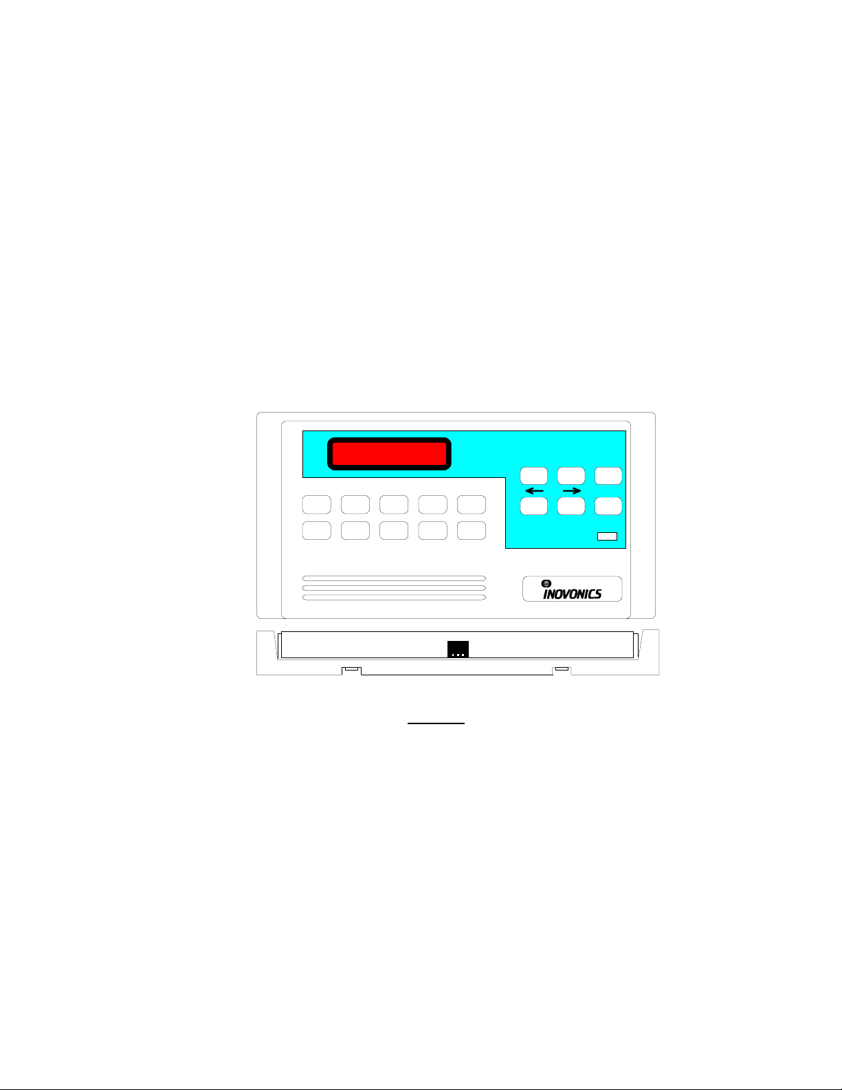
1234
0
56789
FA104 PROGRAMMER
ENTER
POWER
Features
•
Programs all FA-series and C-series receivers and transmitters.
•
Sets receiver and transmitter parameters.
•
Permits transmitter zoning.
•
2-Line x 16-character liquid crystal display.
© 1994 INOVONICS Corporation
1
LIT-FA104-USER 14-Nov-95

Upgrading the C104 Programmer
The Inovonics C104 programmer becomes the FA104 programmer by installing components included in the the F104
upgrade kit.
Elastomer keypad
Microprocessor
(Orient notch as shown)
Contents of the kit
1 transmitter programmming cable small (#1 or #0) phillips head screwdriver
1 microprocessor small slot screwdriver
1 1x3 elastomeric keypad element small paper clip or .032" wire
3 blank keys soldering iron
1 3-pin right-angle header solder
1 graphic overlay label
: Tools needed:
3-pin header
Upgrade Procedure:
1. Replace the C104 graphic label with the FA104 graphic overlay.
2. Place the C104 Programmer upside down on the workbench.
3. Use a small slot screwdriver to release plastic catches at bottom edge and carefully remove back cover.
4. Use a small phillips screwdriver to remove the single screw fastening the PCB board to the front hosing cover.
Carefully lift the PCB away from the front cover. This exposes the keys, so be careful not to accidentally dump
them.
5. Place the 3 blank keys in the unused cutouts in the front cover. Set the front cover aside.
6. Solder the 3-pin header on the PCB as shown. Insert from the component side of the board. The "short" legs go
through the board. Tip: for maximum joint strength, solder the through-hole pins on pads on both sides of the
board. Solder on the component side first, to tack the header in place, then turn the PCB over and put good joints
on the backside pads. Inspect the solder joints carefully for good flow, and make sure that there are no solder
bridges between pads. Finished joints should look "bright and shiny".
7. Insert the paper clip or wire into the holes on the front side of the elastomeric keypad and press the mounting pegs
through the mounting holes in the PCB.
8. Very carefully remove the microprocessor from the socket. If you don't have a special tool for this procedure, use a
small flat screwdriver under the chip body to gradually pry the microprocessor legs out of the socket.
9. Remove the upgrade microprocessor from the anti-electrostatic foam and carefully insert it into the socket. THE
MICRO IS ORIENTED WITH THE POLARIZING NOTCH TOWARD THE CENTER OF THE BOARD. A good
method is to insert all the pins on one side of the socket, then to carefully press the other side in. After insertion,
look closely for bent or buckled leads.
10. Re-assemble the programmer. Tip: when assembling the housing, hook the top hinges first, then snap the bottom
latches into place.
© 1994 INOVONICS Corporation
2
LIT-FA104-USER 14-Nov-95
n
Point
Status
Programming FA416, FA416D and FA464 Receivers
with the FA104 Programmer
Following are descriptions of menu and option displays. Main menu headings are
SETUP, OUTPUT SETUP, PROGRAM POINT, DELETE POINT, CLEAR FAULTS
When the FA104 is first powered up, the display briefly shows software version information, then shows the logo
display, including receiver type:
To enter programming mode, enter the access code. Default access code is
Press ENTER for
Press
!
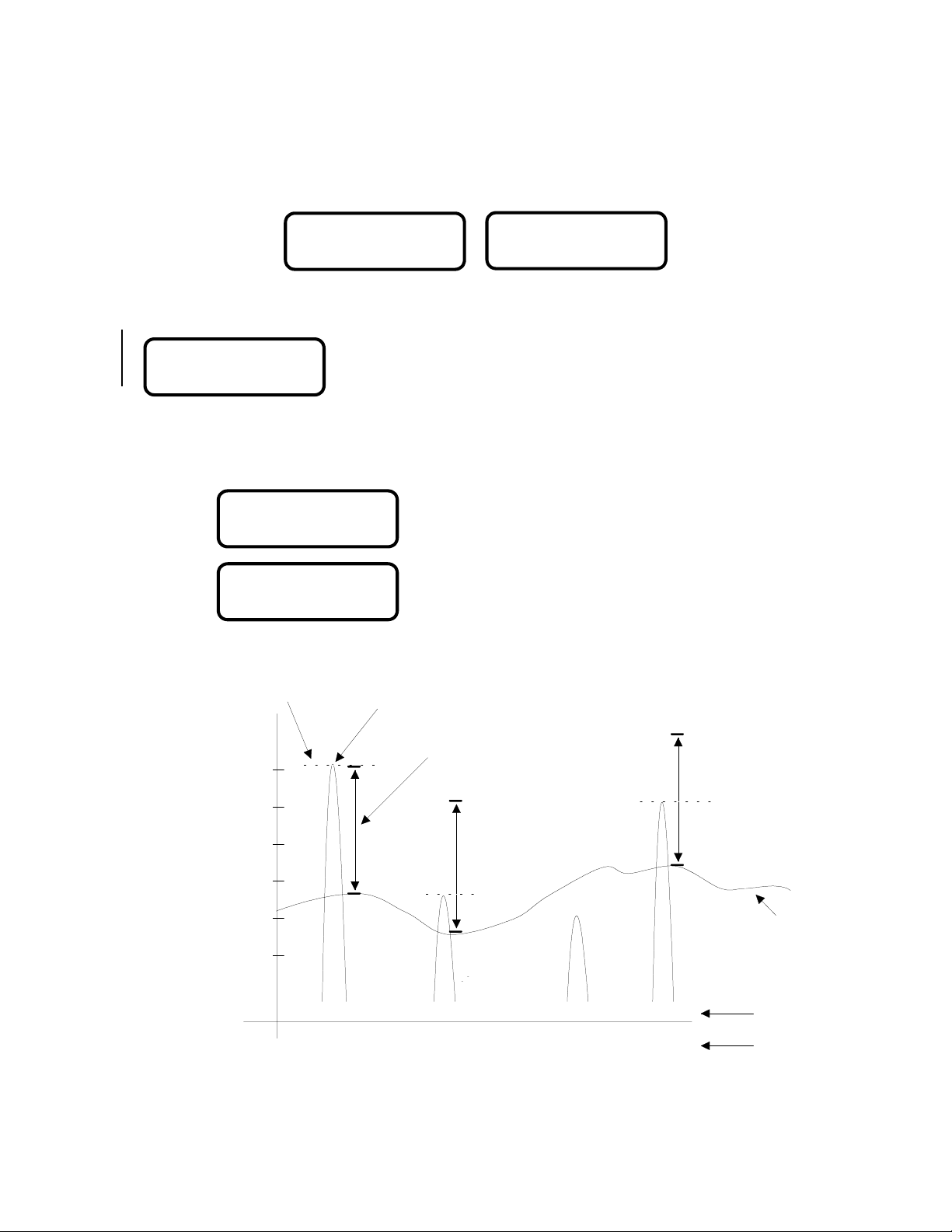
POINT STATUS "
Signal margin
just distinguishable from background) to 33 (strongest). Signal margins below 10 are reported as "Weak".
Signal level
faint).
`
Signal Level (dB)
is an indicator of relative signal strength to background noise. Margin values are from 3 (signal
is an absolute measure of intensity, ranging from about -65dB (very strong) to below -110dB (very
!
1 ALM TMP BATT"
GOOD SIGNAL
!
1 ALM TMP BATT"
LVL:-nnn MAR:+mm
-65dB
INOVONICS FA416
FREQUENCY AGILE
ENTER
Press
!
to go to Receiver Setup menu or press " to go to Test Outputs.
The top line of the display shows the current status of the transmitter.
The second line will read "Good Signal" or "Weak Signal". Press
ENTER
The top line of the display shows the current status of the transmitter.
The bottom line shows real-time values in dB and dBm for signal level
and signal margin. Press
Weak Signal" display.
Received
Signal
Signal Margin Scale
33
INOVONICS FA464
FREQUENCY AGILE
to see signal margins, signal levels and current point status.
to view
ENTER
POINT STATUS, RECEIVER
TEST OUTPUTS
and
3446
. The display will show:
to toggle back to "Good Signal /
33
.
-75dB
-85dB
-95dB
-105dB
-115dB
© 1994 INOVONICS Corporation
33
3
3
33 10
-65dB -100dB
3
Not Received
Not Received
3
18
-75dB
Background
Noise
Signal Margi
Signal Level
LIT-FA104-USER 14-Nov-95
 Loading...