

EN7286NX GE NetworX™ Serial Receiver
A
H
B
B
B
J
K
L
E
D
C
I
B
F
G
M
N
O
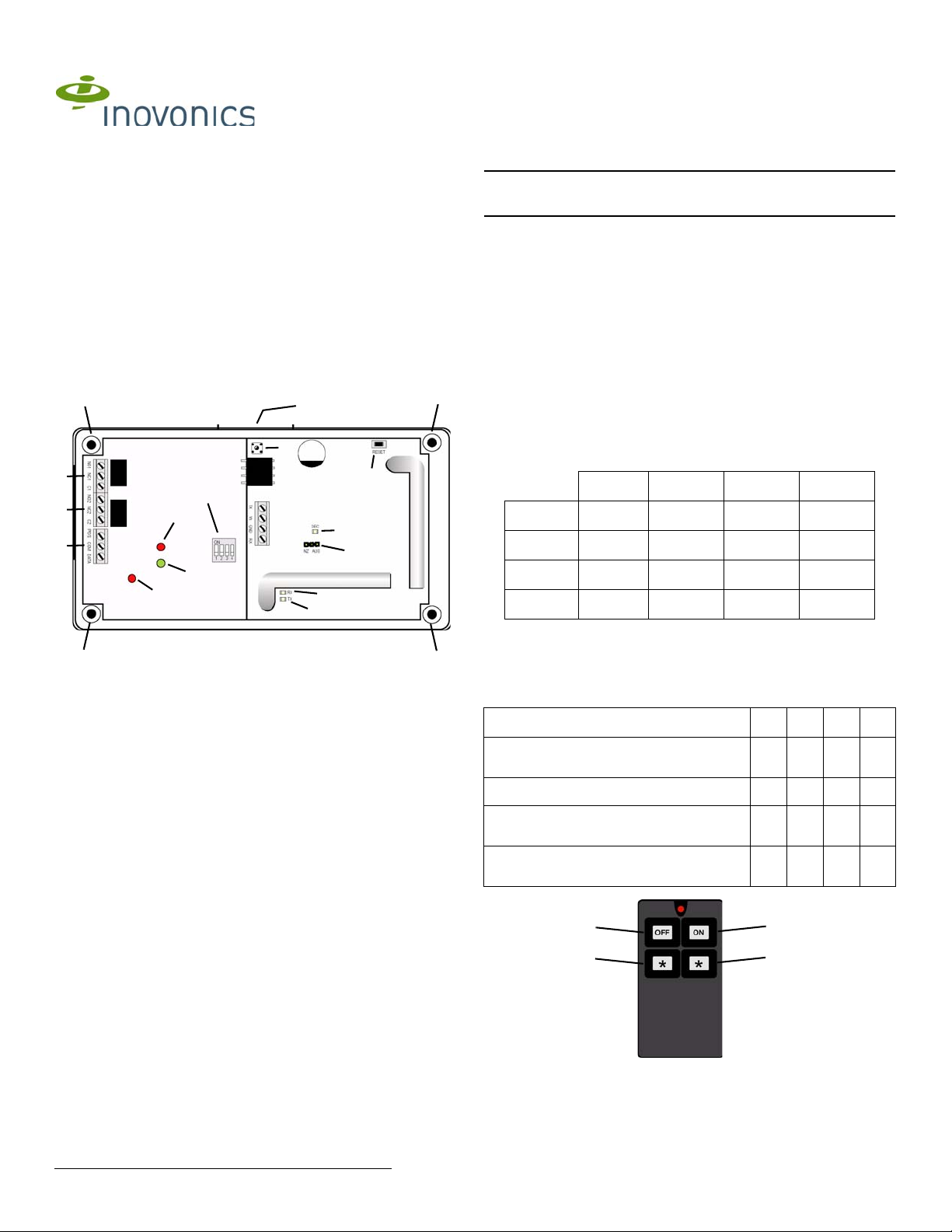
Button 1:
disarm
Button 2:
arm away
Button 3:
arm stay
or relay 2
Button 4:
relay 1
Interface
Installation Instructions - 05938A
1 Overview
The EN7286NX serial receiver interface converts Inovonics EchoStream
wireless messages for compatibility with GE security systems. The
EN7286NX supports 48 wireless points.
1.1 Product Service Information
Contact Inovonics technical services:
• E-mail: support@inovonics.com
• Phone: (800) 782-2709
2 EN7286NX Components
3.2 Connect the EN7286NX to the NX Panel
Caution: Long cable runs should not be adjacent to high current power
feeds. Keep cable lengths as short as possible to minimize noise pickup.
Measure voltage at the serial receiver interface on long cable runs.
1. Connect the serial receiver interface data terminal block (Figure 1, G) to
the NX Panel. Cabling should meet the following specifications:
Cable requirements 4-conductor 20AWG (or larger) stranded-tinned
copper with PVC insulation rated to 300 volts at 26°C (80°F). (Belden
#8205, for example.)
Maximum cable length 30.5 meters (100 feet).
• Connect POS on the power/data terminal block (Figure 1, G) to POS
on the GE NetworX Panel.
• Connect COM on the power/data terminal block (Figure 1, G) to COM
on the GE NetworX Panel.
• Connect DATA on the power/data terminal block (Figure 1, G) to DAT A
on the GE NetworX Panel.
2. Connect the relay 1 (Figure 1, E) and 2 (Figure 1, F) terminal blocks to
external devices as desired.
3.3 Set the Serial Receiver Interface Address
Dipswitches 1 and 2 (Figure 1, H) are used to set the serial receiver
interface address. Use the following table to choose settings appropriate
for your installation:
1234
35
36
37
38
Once you have made your selection, you will need to cycle power to
complete the interface address change.
Off Off
On Off
Off On
On On
3.4 Set Functions on Four-Button Transmitters
Figure 1 EN7286NX components
A Housing release tab B Mounting holes C Housing tamper
D Reset button E Relay 1 terminal
G Power/data terminal
block
J Receiver Receive LED K Receiver Transmit
M Interface Receive LED N Interface Decode
block
H EN7286NX
dipswitches
LED
LED
switch
F Relay 2 terminal
block
I Receiver Decode
LED
L Frequency band
selection pins
O Interface Serial
Receive LED
3 Setup the EN7286NX
Dipswitches 3 and 4 (Figure 1, H) are used to set the functionality of
buttons 3 and 4 on four-button transmitters.
Function 1 2 3 4
Button 3: arm stay; Button 4: relay 1
momentary
Button 3: arm stay; Button 4: relay 1 toggle Off On
Button 3: relay 2 momentary; Button 4: relay
1 momentary
Button 3: relay 2 toggle; Button 4: relay 1
toggle
Off Off
On Off
On On
3.1 Select the Frequency Band
EchoStream products are able to use a range of radio frequencies, and
must be configured for your geographic area. By default, the EN7286NX is
set for the United States. If you want to configure the EN7286NX for a
different geographic area:
1. Use a small screwdriver to press the housing release tab (Figure 1, A);
separate the housing.
2. Place a selection jumper on the appropriate frequency band selection
pins (Figure 1, L).
• Leave the jumper off the pins to set the frequency range to 902-928
MHz for North America.
• Place the jumper on the top two pins, marked AUS, to set the
frequency range to 915-928 MHz for Australia.
• Place the jumper on the bottom two pins, marked NZ, to set the
frequency range to 921-928 MHz for New Zealand.
3. Remove the power source to reset.
© Inovonics, 2010 - www.inovonics.com
Figure 2 Four-button transmitter

4 Programming Location Descriptions
This section describes the programming locations specific to the
EN7286NX serial receiver interface and Inovonics transmitters. For more
information about programming, see the control panel’s installation manual.
4.1 Transmitter Enrollment Location
Location 0
Location 0 is used to initiate the enrollment of transmitters. To enroll
transmitters:
1. Enter the number of the zone to which you wish to enroll the transmitter.
2. Press * to save.
3. Within 150 seconds, press the Reset button on the transmitter you wish
to enroll.
Caution: Make sure the transmitter has not already been registered with
the receiver.
The keypad will sound a chime indicating successful enrollment of the
transmitter; if the zone number does not exist, or if a transmitter has
already enrolled to it, the keypad will sound a triple beep.
Enrollment can be stopped at any point by entering a value of 0.
If auto-increment is enabled in location 193, the next zone value will be
automatically entered into the location, and subsequent transmitters can be
enrolled without returning to the keypad. If there is no successful
enrollment within 150 seconds, the keypad will sound a triple beep.
Enrollment can be stopped at any point by entering a value of 0.
4.2 Transmitter Options Location
Locations 1-192
Up to 48 of these locations can be accessed, depending on the value of the
bank offset value in location 194. Each transmitter has three options that
can be configured.
Standard Transmitter
Option 1-5 Not used
Option 6 Supervision: off = use burg supervision; on = supervised
Option 7 Off = not supervised; on = supervised
Option 8 Off = transmitter disabled; on = transmitter enabled
4.4 Serial Receiver Interface Zone Bank Offset Location
Location 194
Normally this location is set to 0, and the corresponding zones for the serial
receiver interface are 1 through 48. If a panel that supports more than 48
zones is used, this location can be changed to allow the available zones to
start at a higher number in order to reach the highest zones of the panel. As
shown in the following table, each count of 1 in this location increases the
starting zone by 8 up to a maximum 192 zones.
0 Zones 1 - 48
1 Zones 9 - 56
2 Zones 17 - 64
3 Zones 25 - 72
4 Zones 33 - 80
5 Zones 41 - 88
. . . .
18 Zones 145 - 192
4.5 Supervision Window Location
Location 195
Range settings are from 0 - 255, in 10 minute increments. For example, a
setting of 6 will set the supervision window to 60 minutes. The first segment
is used to store the supervision window for a burg/intrusion transmitter and
the second segment is used to store the supervision window for smoke/fire
transmitter. The typical check in time for EchoStream transmitters is 3
minutes.
5 Specifications
Housing dimensions 6.38" x 3.60" x 1.10"(162.0 mm x 91.4 mm x 27.9
mm)
Weight 212 g (6.8 oz)
Power requirement 12 - 14 VDC at 160mA maximum; 80mA normal
Operating environment 0-60°C, (32-140°F) up to 90% relative humidity
(non-condensing)
Operating frequency 902 - 928Mhz
Arm/Disarm Transmitter
Option 1-6 On = activates current partition
Option 7 Off = not supervised; on = supervised
Option 8 Off = transmitter disabled; on = transmitter enabled
These options can be changed once the transmitter is enrolled.
To disable a transmitter, turn option 8 off.
4.3 Serial Receiver Interface Options Location
Location 193
This location sets serial receiver interface options. The location contains
five options.
Option 1 Off = RF jam detection disabled; on = RF jam detection
Option 2 Off = transmitter enrollment is one at a time; on =
Option 3 Off = all arm/disarm devices report as user 99; on =
Option 4 Off = serial receiver interface case tamper disabled, on
Option 5 Off = disarming can occur at any time; on = disarming
enabled
transmitter enrollment is auto incremented
arm/disarm devices report as zone number
= serial receiver interface case tamper enabled
can only occur during entry delay or arm stay
6 Warranty and Disclaimer
Inovonics Wireless Corporation ("Inovonics") warrants its EchoStream
products ("Product" or "Products") to conform to its own specifications and
to be free of defects in materials and workmanship under normal use for a
period of thirty-six (36) months from the date of manufacture. Within the
warranty period, Inovonics will repair or replace, at its option, all or any part
of the warranted Product. Inovonics will not be responsible for dismantling
and/or reinstallation charges. To exercise the warranty, the User ("User",
"Installer" or "Consumer") must work directly through their authorized
distributor who will be given a Return Material Authorization ("RMA")
Number by Inovonics. Details of shipment will be arranged directly through
the authorized distributor.
This warranty is void in cases of improper installation, misuse, failure to
follow installation and operating instructions, alteration, accident or
tampering, and repair by anyone other than Inovonics.
This warranty is exclusive and expressly in lieu of all other warranties,
obligations or liabilities, whether written, oral, express, or implied. There is
no warranty by Inovonics that Inovonics product will be merchantable or fit
for any particular purpose, nor is there any other warranty, expressed or
implied, except as such is expressly set forth herein. In no event shall
Inovonics be liable for an incidental, consequential, indirect, special, or
exemplary damages, including but not limited to loss of profit, revenue or
contract, loss of use, cost of down time, or interruption of business, nor any
claim made by distributor's customers or any other person or entity.
This warranty will not be modified or extended. Inovonics does not
authorize any person to act on its behalf to modify or extend this warranty.
This warranty will apply only to Inovonics Products. Inovonics will not be
liable for any direct, incidental or consequential damage or loss
whatsoever, caused by the malfunction of Product due to products,
accessories, or attachments of other manufacturers, including batteries,
used in conjunction with Inovonics Products.
© Inovonics, 2010 - www.inovonics.com 2
 Loading...