

EN6080 Area Control Gateway
A
B
C
Installation Instructions
1 Overview
The Inovonics EN6080 area control gateway bridges the proprietary
Inovonics commercial mesh network to a standard TCP-IP over Ethernet
LAN. Featuring a PSIA 0.8 compliant set of RESTful web services, the
EN6080 area control gateway is designed to ensure interoperability with
other IP-enabled devices across the security industry.
1.1 Installing an Inovonics Security System
An EchoStream survey kit should be used to establish an EchoStream
system. The EchoStream survey kit measures the signal strength of highpower repeater and sensor messages to help optimize your EchoStream
system.
1.2 Maximum Number of Repeaters for a UL 2560
Installation
To achieve the 99.99% alarm message reliability required for UL 2560
compliance, system installations must operate within the following limits for
end device and repeater counts.
End Devices Maximum
150 397
250 386
350 375
500 360
1000 313
2000 238
3000 184
Repeaters
1.3 Inovonics Wireless Contact Information
If you have any problems with this procedure, contact Inovonics Wireless
technical services:
• E-mail: support@inovonics.com
• Phone: (800) 782-2709; (303) 939-9336
1.4 EN6080 Area Control Gateway Front Panel
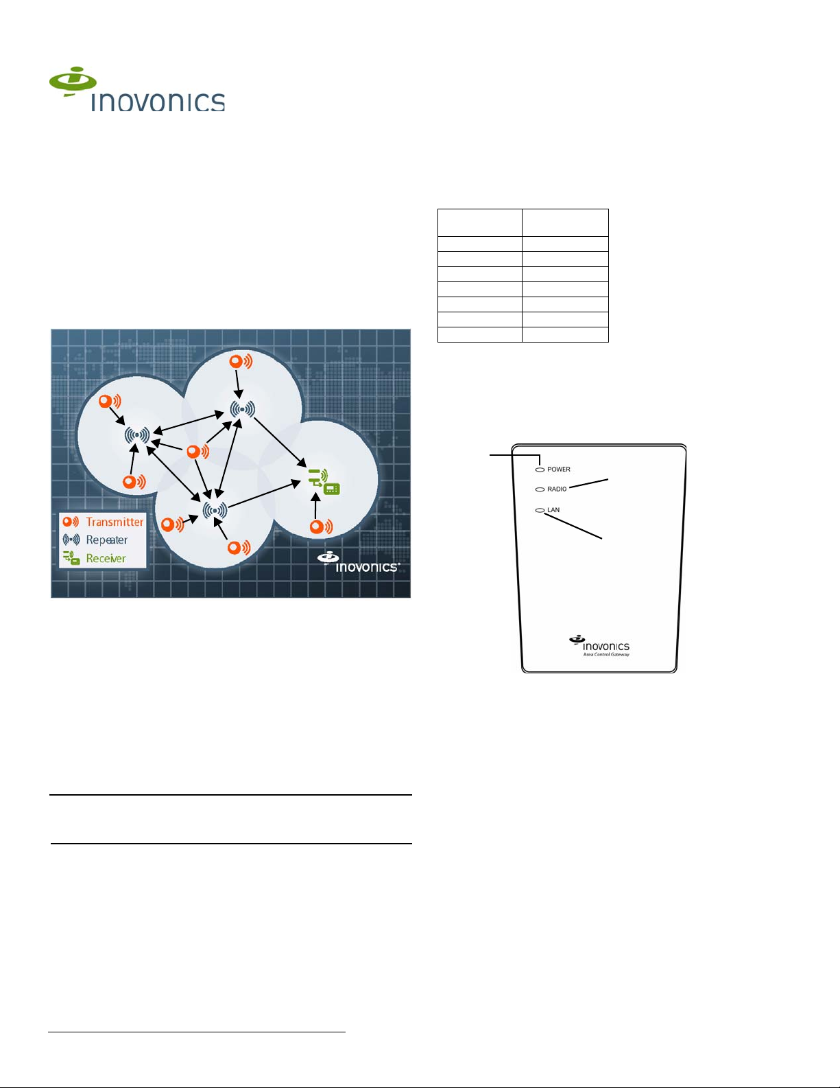
Figure 1 Sample EchoStream system
The EchoStream survey kit provides you with two signal strength
measurements: signal level and signal margin.
Signal level
The signal level is the measurement of the overall decibel level of the
message.
Signal margin
The signal margin is the measurement of the decibel level of the message,
minus the decibel level of any interfering signals. Inovonics equipment
should be placed within a facility such that all end-devices produce signal
margin readings of at least 4 decibels.
Both the signal level and signal margin are measured in decibels. Because
signal strength and signal margin are measured on a logarithmic scale, the
difference between a decibel level of 3 (Weak) and a decibel level of 4
(Good) is a much larger difference than it would be on a linear scale.
Note: For more information about the EchoStream survey kit, see the
EN/EE7016SK EchoStream
Manual.
® Survey Kit Installation and Operation
Figure 2 EN6080 area control gateway front panel
A Power LED B Radio LED C LAN LED
Operation LEDs
Power LED: Green indicates the presence of line power or power over
Ethernet.
Radio LED: Green indicates that the device is decoding messages from the
wireless network.
LAN LED: Green indicates Ethernet link; flashing indicates Ethernet
activity.
4.18.14 06369D © Inovonics, 2014 - www.inovonics.com
1.5 EN6080 Area Control Gateway Inter nal Components
A
A
A
A
B
C
D
G
F
E
H
I
I
J
K
L
M
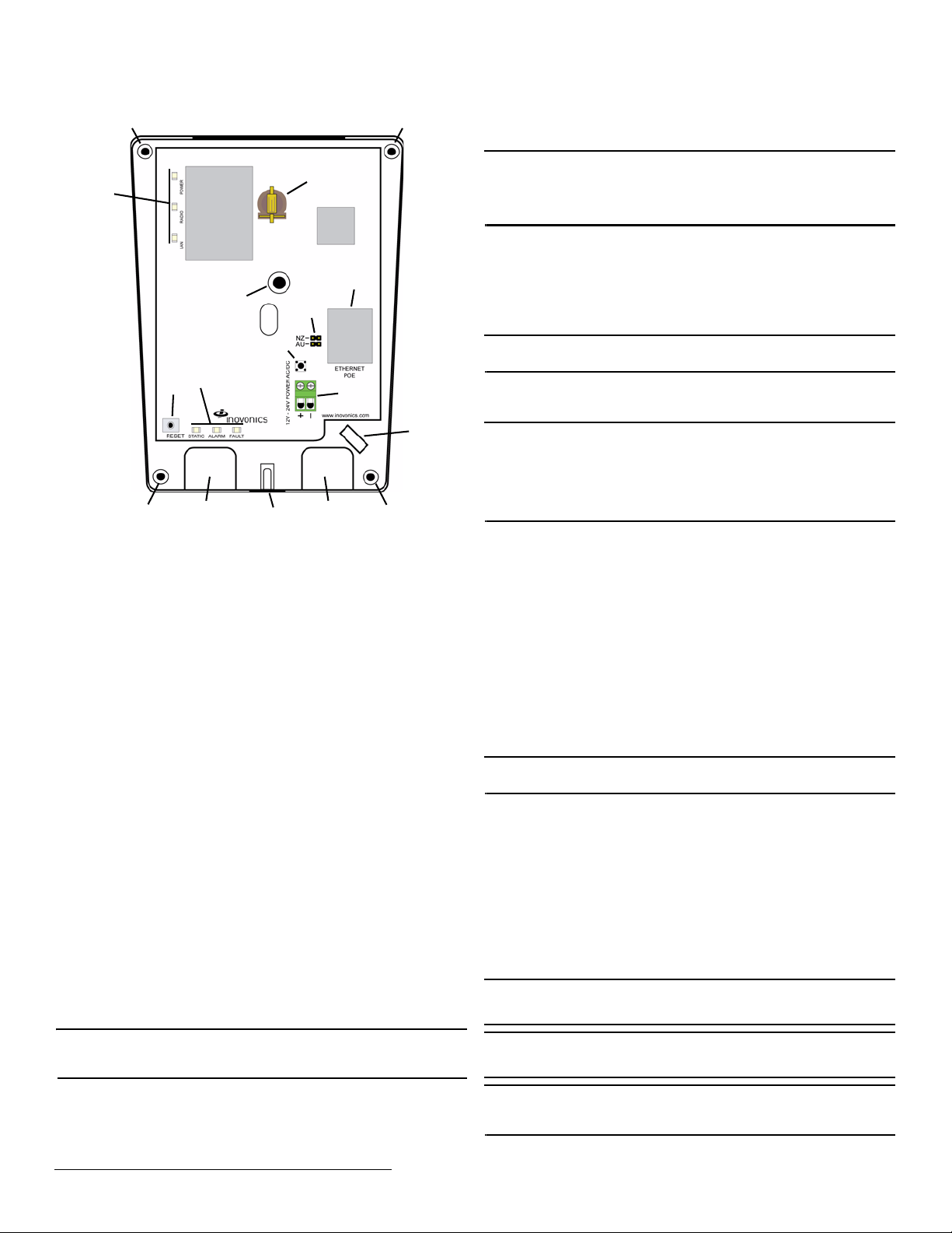
Figure 3 EN6080 area control gateway internal components
A Wall mount holes B Housing cover release
D RJ45 Ethernet jack E Operation LEDs F Diagnostic LEDs
G Frequency band
selection pins
J Wall tamper mounting
hole
M Battery holder
screw
H Reset button I Cabling port
K Housing tamper switch L Cabling tie loop
C Power connection
terminal block
Diagnostic LEDs
Static LED: Yellow indicates the EN6080 is using a static IP address; green
indicates the EN6080 is using a dynamic IP address obtained from the
network; no illumination indicates the EN6080 has been configured to use
a dynamic IP address but has not obtained one from the network, or there
is no Ethernet connection.
Alarm LED: Red indicates an alarm in the wireless network.
Fault LED: Yellow indicates a tamper, low battery or repeater line power
loss fault in the wireless network.
1.6 What’s in the Carton
• One CR1220 backup battery
• Five drywall anchors
• Five mounting screws
• One frequency band selection jumper
2 Installation and Startup
2.1 Installation Notes
• These products are designed to be maintained by professional
security technicians.
• Products are tested for indoor use.
• All products should be manually tested weekly.
2.2 Connect Power Cabling and Install Backup Battery
Note: The EN6080 area control gateway is Power over Ethernet (PoE)
capable on any network supporting the IEEE 802.3at-2009 PoE+ standard.
Power over Ethernet will only function when line power is not present.
To use line power, you will need to connect a power source to the EN6080
area control gateway. To do so:
1. Use a Phillips screwdriver to loosen the housing cover release screw
2. Lift the cover off the hinges on the top of the housing.
(Figure 3).
3. Route the power cabling through the cabling ports on the bottom of the
housing (Figure 3).
• If not using the included ACC610 14 VAC/20VA transformer, use 1422 guage wire for all cabling.
Note: For UL 2560 installations, all cabling must be UL Listed or
Recognized, Class 2 wire suitable for the application. If connecting cabling
to a DC power source, such as the included transformer, use twoconductor 14-22 AWG stranded-tinned copper, rated 300 volts, 60°C
minimum.
4. Connect to the power connection terminal block.
• If connecting cabling to a DC power source, ensure polarity
corresponds to the + and - connections; an AC power source does not
require specific polarity and can use either connection.
• Ensure torque on the screw terminals does not exceed 0.35 - 0.4 Nm
(3.1 - 3.5 inch-pounds).
5. Insert the backup battery in the battery holder (Figure 3).
Note: It is a best practice to install the backup battery just prior to powering
on the EN6080 area control gateway.
6. Connect the power cabling to your power source.
• The power source must be 12-24 VAC or VDC. The power supply
must be unswitched, uninterrupted and regulated.
Note: For UL 2560 installations, a Class 2 plug-in transformer, rated
14VAC/120VAC-20VA, must be used with the EN6080 area control
gateway if Power over Ethernet is not provided. Approved Class 2
transformers include the MPI-NEO Co., Ltd., Model W48A-K1429-2T
transformer availabe from Inovonics as part number ACC610, as well as
the Good Power Electronics, Ltd., Model T48141428V010G or
T48141428V020G transformers.
2.3 Select the Frequency Band
EchoStream devices are able to use a range of radio frequencies, and must
be configured for your geographic area. This device ships with a default
frequency range of 902-928 MHz for use in North America. If you are using
the device in North America, skip to 2.4, “Connect Ethernet Cabling”; if you
are using the device in Australia or New Zealand, you will need to configure
it.
7. Place a selection jumper on the frequency band selection pins
appropriate to your geographic area (Figure 3).
• Place the jumper on the top two pins, marked NZ, to set the frequency
range to 921-928 MHz for New Zealand
• Place the jumper on the bottom two pins, marked AUS, to set the
frequency range to 915-928 MHz for Australia.
8. Press the reset button to complete configuration (Figure 3).
2.4 Connect Ethernet Cabling
Note: For UL 2560 installations, a UL Certified PoE switch or injector must
be used if the EN6080 area control gateway is to be powered with PoE.
The EN6080 area control gateway connects to network components in a
wired local area network (LAN) using the RJ45 Ethernet jack. T o connect to
a LAN:
9. Connect one end of a RJ45 Ethernet cable to the RJ45 Ethernet jack on
the EN6080 area control gateway (Figure 3).
10. Route the Ethernet cable through the cabling ports on the bottom of the
housing (Figure 3).
11. Connect the other end of the RJ45 Ethernet cable to an RJ45 Ethernet
jack connected to your LAN.
12. To relieve stress on the Ethernet and power cabling, secure it to the
cabling tie loop with a tie (Figure 3).
2.5 Mount the EN6080 Area Control Gateway
Caution: Mount the EN6080 area control gateway in a location removed
from metal. Metal objects (duct work, wire mesh screens, boxes) will
reduce RF range.
Caution: Per FCC RF exposure requirements, the EN6080 should be
mounted in a location where it will be no closer than 100cm from nearby
persons.
Note: To meet UL 2560 requirements, the EN6080 area control gateway
must be mounted in a manner that allows the cable openings to face
downward.
4.18.14 06369D © Inovonics, 2014 - www.inovonics.com 2

The EN6080 area control gateway includes a wall tamper. If the EN6080
area control gateway is removed from the wall, the cutout on the back of
the housing will detach, activating a tamper alarm. The wall tamper will only
work if the EN6080 area control gateway is properly installed. To ensure
the EN6080 is properly installed, carefully follow the mounting instructions:
13. If mounting the EN6080 area control gateway to drywall, install the
drywall anchors included in the installation packet.
Caution: If the EN6080 area control gateway is mounted to drywall, the
drywall anchors must be used. Without the drywall anchors, the back
tamper will not activate if the device is removed from the wall.
14. Use four of the the provided screws to mount the EN6080 area control
gateway, making sure the EN6080 area control gateway is flush with
the wall (Figure 3).
15. Attach one of the provided screws to the wall through the wall tamper
mounting hole (Figure 3).
Caution: Tighten the wall tamper screw to a snug fit without over-tightening
it. Overtightening the wall tamper screw can break the wall tamper cutout,
disabling the wall tamper.
16. Check that the housing tamper spring is in place and makes contact
with the top of the housing (Figure 3).
17. Close the housing.
18. Tighten the housing cover release screw.
19. Navigate to http://www.inovonics.com/product/area-control-gateway/ to
access the EN6080 Area Control Gateway User Manual which will
guide you through setup and configuration. Instructions for connecting
to the EN6080 area control gateway are included.
3 US Patent Numbers
• 7,154,866
• 7,554,932
• 7,746,804
• Other patents pending
4 Specifications
Compatible repeater, transmitters: EN5040, EN5040-T, EN5040-20T,
EN1210, EN1210W, EN1210EOL, EN1212, EN1215EOL, EN1215WEOL,
EN1216, EN1223D, EN1223S, EN1224, EN1224-ON, EN1233D,
EN1233S, EN1235D, EN1235DF, EN1235S, EN1235SF, EN1236D,
EN1238D, EN1240, EN1242, EN1247, EN1249, EN1252, EN1260,
EN1261HT, EN1262, EN1265, EN1941
Dimensions: 5.25” x 6.75” x 1.25”
Weight: 12 oz
Interface: 100Base-T Ethernet
Operating environment: -4 to140°F (-20 to 60°C), 90% relative humidity,
non-condensing
Power requirement: 12-24 VDC/AC; 500mA
Operating frequency: 902-928 MHz, Frequency hopping spread spectrum
Tamper: Type B, fixed device
UL certification: UL 2560 (see conditions below)
Note: For UL 2560 installations, Inovonics repeaters must have 20 minute
check-in times. Inovonics transmitters must have a minimum of 60 minute
check-in times.
Note: Users that have achieved certification and will install UL 2560
certified systems are responsible for labeling all fundamental devices with
the UL 2560 system certification mark.
5 Television and Radio Interference
This equipment has been tested and found to comply with the limits for a
Class B digital device, pursuant to Part 15 of the FCC Rules. These limits
are designed to provide reasonable protection against harmful interference
in a residential installation. This equipment generates, uses and can
radiate radio frequency energy and, if not installed and used in accordance
with the instructions, may cause harmful interference to radio
communications. However, there is no guarantee that interference will not
occur in a particular installation. If this equipment does cause harmful
interference to radio or television reception, which can be determined by
turning the equipment off and on, the user is encouraged to try to correct
the interference by one or more of the following measures:
• Reorient or relocate the receiving antenna.
• Increase the separation between the equipment and receiver.
• Connect the equipment into an outlet on a circuit different from that to
which the receiver is connected.
• Consult the dealer or an experienced radio/TV technician for help.
6 FCC Part 15 and Industry Canada Compliance
This device complies with part 15 of the FCC Rules and Industry Canada
license-exempt RSS standard(s). Operation is subject to the following two
conditions: (1) this device may not cause interference, and (2) this device
must accept any interference, including interference that may cause
undesired operation of the device.
Le présent appareil est conforme aux CNR d'Industrie Canada applicables
aux appareils radio exempts de licence. L'exploitation est autorisée aux
deux conditions suivantes : (1) l'appareil ne doit pas produire de brouillage,
et (2) l'utilisateur de l'appareil doit accepter tout brouillage radioélectrique
subi, même si le brouillage est susceptible d'en compromettre le
fonctionnement.
Caution: Changes or modifications not expressly approved by the party
responsible for compliance could void the user's authority to operate the
equipment.
Note: In a UL 2560 installation, the EN6080 area control gateway may be
used with completed emergency call systems for assisted living and
independent living facilities
For UL 2560 certified system installations, the following Inovonics
EchoStream devices are approved for installation within maximum system
configuration limits defined in section 1.2 of this document:
• EN6080 area control gateway
• EN5040-20T high power repeater
• End devices (transmitters) with a minimum 60-minute check-in
interval, as follows:
- Fundamental devices which are subject to UL2560 certification
(pendant transmitters and OEM products using the Inovonics RF
module)
- Supplemental devices which are not subject to UL2560 system
certification but which may be used within a UL2560 certified system
(e.g. universal transmitters and activity sensors)
4.18.14 06369D © Inovonics, 2014 - www.inovonics.com 3
 Loading...