

EN6040 Network Coordinator
A
C
D
B
F
B
G
C
D
E
A
A
A
H
Installation Instructions
1 Overview
The EN6040 network coordinator is a gateway that uses reliable frequencyhopping, spread-spectrum technology to coordinate signals between end
devices, high-power repeaters and the application controller in a common
serial data format.
1.1 Installing an Inovonics Security System
An EchoStream survey kit should be used to establish an EchoStream
system. The EchoStream survey kit measures the signal strength of highpower repeater and sensor messages to help optimize your EchoStream
system.
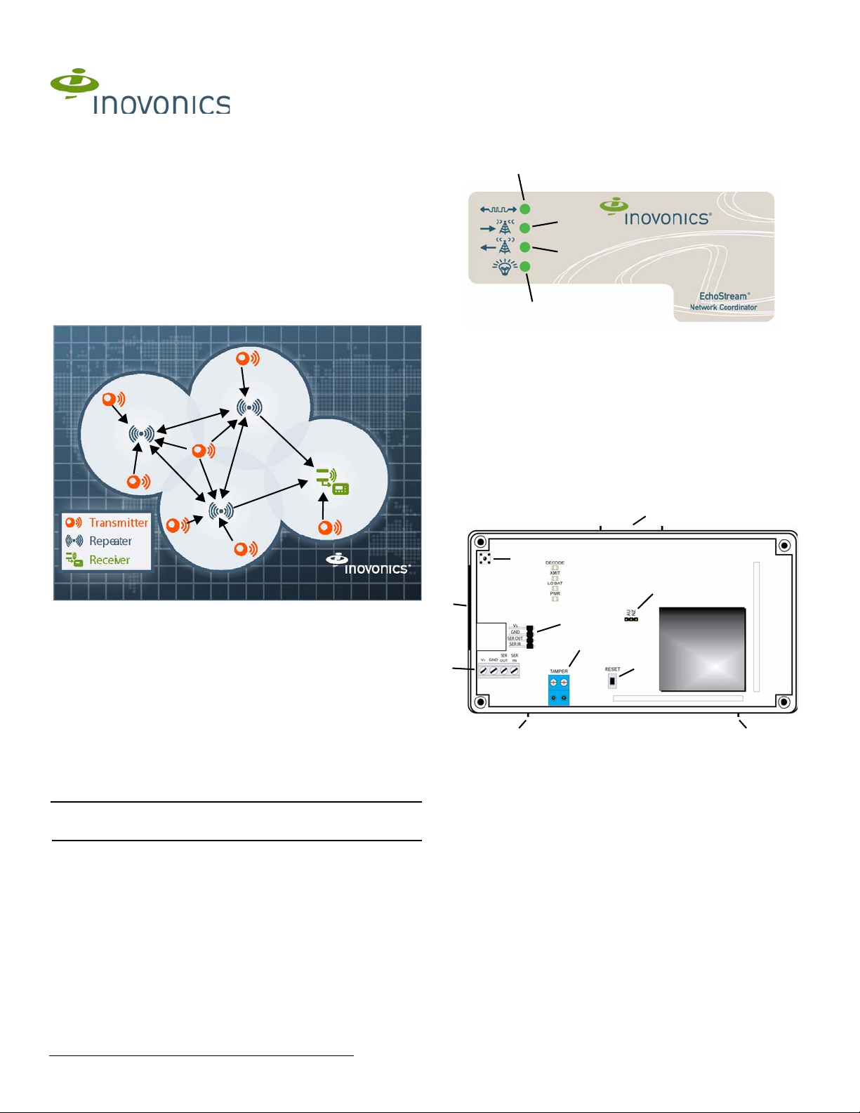
1.3 EN6040 Network Coordinator Front Panel
Figure 2 EN6040 network coordinator front panel
A Serial Data
LED
B RF Receive
LED
C RF Transmit
LED
D Power LED
Operation LEDs
Serial Data LED: Lit when the EN6040 network coordinator is receiving or
transmitting serial data.
RF Receive LED: Lit when the EN6040 network coordinator is receiving a
RF transmission from another Inovonics Wireless device.
RF Transmit LED: Lit when the EN6040 network coordinator is transmitting
an RF transmission to an end device or high-power repeater.
Power LED: Lit when the EN6040 network coordinator is receiving power.
1.4 EN6040 Network Coordinator Internal Components
Figure 1 Sample EchoStream system
The EchoStream survey kit provides you with two signal strength
measurements: signal level and signal margin.
Signal level
The signal level is the measurement of the overall decibel level of the
message.
Signal margin
The signal margin is the measurement of the decibel level of the message,
minus the decibel level of any interfering signals. Inovonics equipment
should be placed within a facility such that all end-devices produce signal
margin readings of at least 4 decibels.
Both the signal level and signal margin are measured in decibels. Because
signal strength and signal margin are measured on a logarithmic scale, the
difference between a decibel level of 3 (Weak) and a decibel level of 4
(Good) is a much larger difference than it would be on a linear scale.
Note: For more information about the EchoStream survey kit, see the
EN7016SK EchoStream® Survey Kit Installation and Operation Manual.
Figure 3 EN6040 network coordinator internal components
A Housing release tab B Frequency band selection pins
C Serial data and power terminal D Tamper terminal
E Serial data and power port F Reset button
G Housing tamper switch H Side cabling knockout
1.5 What’s In The Carton
1.2 Inovonics Wireless Contact Information
If you have any problems with this procedure, contact Inovonics Wireless
technical services:
• E-mail: support@inovonics.com
• Phone: (800) 782-2709; (303) 939-9336
• Two drywall anchors
• Two mounting screws
• Two pieces of mounting tape
• One frequency band selection shunt
2 Installation and Startup
2.1 Installation Notes
• These products are designed to be maintained by professional
security technicians
• Products are tested for indoor use
• All products should be manually tested weekly
3.1.13 05171C © Inovonics, 2013 - www.inovonics.com

2.2 Connect Power, Serial, and Tamper Cabling
Caution: Long cable runs should not be adjacent to high current power
feeds. Keep cable lengths as short as possible to minimize noise pickup.
Measure voltage at the EN6040 network coordinator on long cable runs.
1. Use a small screwdriver to press the top housing release tab and
separate the housing (Figure 3).
2. If using the Inovonics ACC643 serial and power cable to connect the
EN6040 network coordinator, connect it to the serial data and power
port (Figure 3).
3. If using a serial data and power cable of your own design, connect it to
the serial data terminal (Figure 3). Cabling should meet the following
specifications:
• A maximum cable length of 50 feet (15.25 meters).
4. If an external tamper switch is needed, connect a cable to the tamper
terminal (Figure 3). Tamper cabling should meet the following
specifications:
• A maximum cable length of 50 feet (15.25 meters).
5. Route the cabling through the side cabling knockout (Figure 3).
2.3 Select the Frequency Band
EchoStream products are able to use a range of radio frequencies, and
must be configured for your geographic area. This product ships with a
default frequency range of 902-928 MHz for use in North America. If you
are using the product in North America, skip to section 2.4, “Mount the
EN6040 Network Coordinator”; if you are using the product in Australia or
New Zealand, you will need to configure the EN6040 network coordinator.
6. Place a selection jumper on the frequency band selection pins
appropriate to your geographic area (Figure 3).
• Place the jumper on the right two pins, marked NZ, to set the
frequency range to 921-928 MHz for New Zealand
• Place the jumper on the left two pins, marked AUS, to set the
frequency range to 915-928 MHz for Australia.
7. Press the reset button to complete configuration (Figure 3).
2.4 Mount the EN6040 Network Coordinator
Caution: Mount the EN6040 network coordinator in a location removed
from metal. Metal objects (duct work, wire mesh screens, boxes) will
reduce RF range.
Note: A best practice is to ensure the EN6040 network coordinator is
mounted in an easily accessible location for future maintenance.
8. If using the mounting tape included in the installation packet, apply the
tape to the back of the housing and to the wall.
9. If using the mounting screws to mount the EN6040 network coordinator
to drywall, install the drywall anchors included in the installation packet.
10. Use the provided screws to mount the EN6040 network coordinator.
11. Once the EN6040 network coordinator has been mounted, close the
housing.
3 US Patent Numbers
• 7,154,866
• 7,554,932
• 7,746,804
4 Specifications
Housing dimensions: 165 mm x 89 mm x 25 mm (6.5" x 3.5" x 1")
Weight: 161 g (5.7 oz)
Power requirement: 10-14 VDC at 200mA
Radio: Inovonics Wireless EchoStream
Operating frequency: 915-928 MHz (Australia), 921-928 MHz (New
Zealand), 902-928 MHz (USA)
Operating environment: -20 - 60°C (-4°- 140°F), 90% relative humidity, non-
condensing
Accessories: ACC643: serial data and power cord
5 Television and Radio Interference
This equipment has been tested and found to comply with the limits for a
Class B digital device, pursuant to Part 15 of the FCC Rules. These limits
are designed to provide reasonable protection against harmful interference
in a residential installation. This equipment generates, uses and can
radiate radio frequency energy and, if not installed and used in accordance
with the instructions, may cause harmful interference to radio
communications. However, there is no guarantee that interference will not
occur in a particular installation. If this equipment does cause harmful
interference to radio or television reception, which can be determined by
turning the equipment off and on, the user is encouraged to try to correct
the interference by one or more of the following measures:
• Reorient or relocate the receiving antenna.
• Increase the separation between the equipment and receiver.
• Connect the equipment into an outlet on a circuit different from that to
which the receiver is connected.
• Consult the dealer or an experienced radio/TV technician for help.
6 FCC Part 15 and Industry Canada Compliance
This device complies with part 15 of the FCC Rules and Industry Canada
license-exempt RSS standard(s). Operation is subject to the following two
conditions: (1) this device may not cause interference, and (2) this device
must accept any interference, including interference that may cause
undesired operation of the device.
Le présent appareil est conforme aux CNR d'Industrie Canada applicables
aux appareils radio exempts de licence. L'exploitation est autorisée aux
deux conditions suivantes : (1) l'appareil ne doit pas produire de brouillage,
et (2) l'utilisateur de l'appareil doit accepter tout brouillage radioélectrique
subi, même si le brouillage est susceptible d'en compromettre le
fonctionnement.
7 Warranty and Disclaimer
Caution: Changes or modifications not expressly approved by the party
responsible for compliance could void the user's authority to operate the
equipment.
Inovonics Wireless Corporation (“Inovonics”) warrants its products
(“Product” or “Products”) to conform to its own specifications and to be free
of defects in materials and workmanship under normal use for a period of
thirty-six (36) months from the date of manufacture. Within the warranty
period, Inovonics will repair or replace, at its option, all or any part of the
warranted Product. Inovonics will not be responsible for dismantling and/or
reinstallation charges. T o exercise the warranty, the User (“User”, “Installer”
or “Consumer”) must work directly through their authorized distributor who
will be given a Return Material Authorization (“RMA”) Number by Inovonics.
Details of shipment will be arranged directly through the authorized
distributor.
This warranty is void in cases of improper installation, misuse, failure to
follow installation and operating instructions, alteration, accident or
tampering, and repair by anyone other than Inovonics.
This warranty is exclusive and expressly in lieu of all other warranties,
obligations or liabilities, whether written, oral, express, or implied. There is
no warranty by Inovonics that Inovonics product will be merchantable or fit
for any particular purpose, nor is there any other warranty, expressed or
implied, except as such is expressly set forth herein. In no event shall
Inovonics be liable for an incidental, consequential, indirect, special, or
exemplary damages, including but not limited to loss of profit, revenue or
contract, loss of use, cost of down time, or interruption of business, nor any
claim made by distributor's customers or any other person or entity.
This warranty will not be modified or extended. Inovonics does not
authorize any person to act on its behalf to modify or extend this warranty.
This warranty will apply only to Inovonics Products. Inovonics will not be
liable for any direct, incidental or consequential damage or loss
whatsoever, caused by the malfunction of Product due to products,
accessories, or attachments of other manufacturers, including batteries,
used in conjunction with Inovonics Products.
3.1.13 05171C © Inovonics, 2013 - www.inovonics.com 2
 Loading...