

EN5040/EN5040-T/EN5040-20T High Power
A
B
D
C
A
A
A
C
D
F
G
B
E
H
I
J
Repeater with Transformer
Installation and Operation Manual
1 Overview
The Inovonics high power repeater receives, decodes and retransmits
signals at enhanced power from Inovonics devices. It acts as a range
expander for any valid Inovonics transmission, including signals from other
high power repeaters. High power repeaters can be layered as necessary,
allowing Inovonics systems to scale from small commercial sites to
complete campuses consisting of several buildings. The high power
repeater features AC power loss and jam detection, as well as case tamper
and wall tamper detection. Input power is provided by listed class 2
transformer, Good Power Electronics, Ltd. T48141428V010G or
T48141428V020G, MPI-NEO Co., Ltd. W48A-K1429-2T.
Note: For UL 2560 installations, refer to the EN6080 Area Control Gateway
User Manual; for other UL installations, refer to the EN4216MR Installation
and Operation Manual, the EN4232MR Installation and Operation Manual,
or the EN7285 Installation Instructions.
1.4 High Power Repeater Internal Components
1.1 Maximum Number of Repeaters for a UL 2560
Installation
To achieve the 99.99% alarm message reliability required for UL 2560
compliance, system installations must operate within the following limits for
end device and repeater counts.
End Devices Maximum
150 397
250 386
350 375
500 360
1000 313
2000 238
3000 184
Repeaters
1.2 Inovonics Contact Information
If you have any problems with this procedure, contact Inovonics technical
services:
• E-mail: support@inovonics.com
• Phone: (800) 782-2709; (303) 939-9336
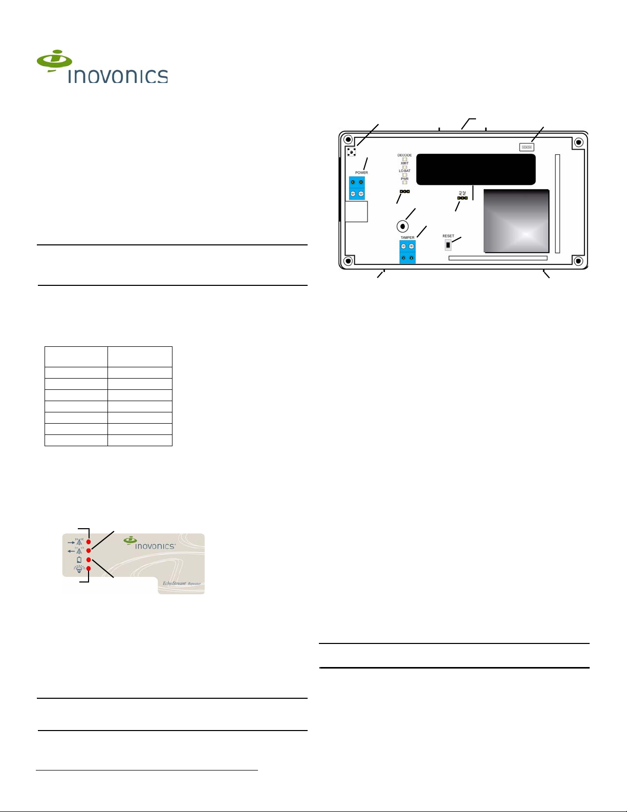
1.3 High Power Repeater Front Panel
Figure 1 High power repeater front panel
A Decode LED B Transmit LED C Low Battery Fault LED
D Power LED
Operation LEDs
Decode LED: Flashes when any recognizable RF transmission is received.
Transmit LED Lit when transmitting an RF transmission.
Low Battery Fault LED: Lit when the high power repeater has a low battery.
Power LED: Lit when receiving power. The LED lights green when the unit
is receiving line power; red when receiving battery power.
Note: If mapped to an output, the high power repeater will send the AC loss
message to the EN6080 area control gateway when receiving power from
the backup battery.
Figure 2 High power repeater internal components
A Housing release
tabs
E Reset button F Backup battery G Battery
I Frequency
selection pins
B Tamper button
spring
J Messaging mode
selection pins
C Power D Tamper input
connector
H Tamper
mounting hole
1.5 What’s in the Carton
• One 14VAC/120VAC-20VA power transformer
• Three drywall anchors
• Three mounting screws
• One frequency band selection jumper
2 Installation and Startup
2.1 Installation Notes
• These products are designed to be maintained by professional
security technicians
• Products are tested for indoor use
• All products should be manually tested weekly
2.2 Select the Frequency Band
EchoStream devices are able to use a range of radio frequencies, and must
be configured for your geographic area. This device ships with a default
frequency range of 902-928 MHz for use in North America. If you are using
the device in North America, skip to 2.3, “Choose Messaging Mode”; if you
are using the device in Australia or New Zealand, you will need to configure
it.
1. Use a small screwdriver to press the top housing release tab and
separate the housing (Figure 2).
2. Place a selection jumper on the frequency band selection pins
appropriate to your geographic area (Figure 2).
• Place the jumper on the left two pins, marked AU, to set the frequency
range to 915-928 MHz for Australia.
• Place the jumper on the right two pins, marked NZ, to set the
frequency range to 921-928 MHz for New Zealand.
Note: Only devices set for use in North America are configured for UL
installations.
2.3 Choose Messaging Mode
The EchoStream commercial mesh network includes two kind of
messaging: broadcast messaging and directed messaging. The high power
repeater includes a messaging selection option to protect the integrity of
your system. The high power repeater ships with a default setting of
broadcast messaging. If you are installing the device in a broadcast
messaging network, skip to section 2.6, “Register the High Power
Repeater”; if you are installing the high power repeater in a directed
messaging network, you will need to configure it.
1.23.14 05066N © Inovonics, 2014 - www.inovonics.com
3. To set the high power repeater to directed messaging, remove the
Antenna
Antenna
selection jumper installed on the messaging mode selection pins.
2.4 Connect Power Cabling
Power must be connected to the high power repeater. To connect power to
the high power repeater:
4. Use a small screwdriver to press the housing release tab on the top or
bottom of the high power repeater (Figure 2); separate the housing.
5. Connect power cabling (Figure 2).
• Wire should be two-conductor 20AWG (or larger) stranded-tinned
copper with PVC insulation rated to 300 volts at 26°C (80°F). Wire
length should not exceed 100 meters (328 feet).
Note: For all UL installations, cabling must be UL Listed or Recognized,
Class 2 wire suitable for the application. Use two-conductor 20 AWG (or
larger) stranded-tinned copper, rated 300 volts, 60°C minimum. Wire length
should not exceed 100 meters.
• See section 1, “Overview” on page 1 for approved Class 2
transformers.
• Route the cable from the transformer to the unit through the left side of
the repeater, or through the oval knock-out section in the rear.
• Torque screw terminal to 0.25 N-m (2.18 lb-in).
Note: Do not secure transformer for Canadian installations.
2.5 Connect Battery Power
The high power repeater is shipped with a fully-charged backup battery.
You will need to connect the battery:
6. Plug the connector cable from the backup battery into the battery
connector (Figure 2).
2.6 Register the High Power Repeater
Although the high power repeater is functional upon startup, Inovonics
strongly recommends you register it using the EN6080 area control
gateway. Inovonics recommends all high power repeaters be supervised.
When supervised, the EN5040 and EN5040-T will send a check-in
message to the receiver every three minutes; the EN5040-20T will send a
check-in message every 20 minutes.
Note: In UL 2560 installations, the repeater sends a check-in message
every 20 minutes.
Note: Registration and supervision is required for UL installations.
Note: In UL 2560 installations, refer to the EN6080 Area Control Gateway
User Manual for registration information; in other UL installations, refer to
the EN4216MR Installation and Operation Manual, the EN4232MR
Installation and Operation Manual, or the EN7285 Installation Instructions.
Caution: The reset bit will not be sent when the high power repeater has a
low battery. Before registering the high power repeater, ensure the battery
is fully charged.
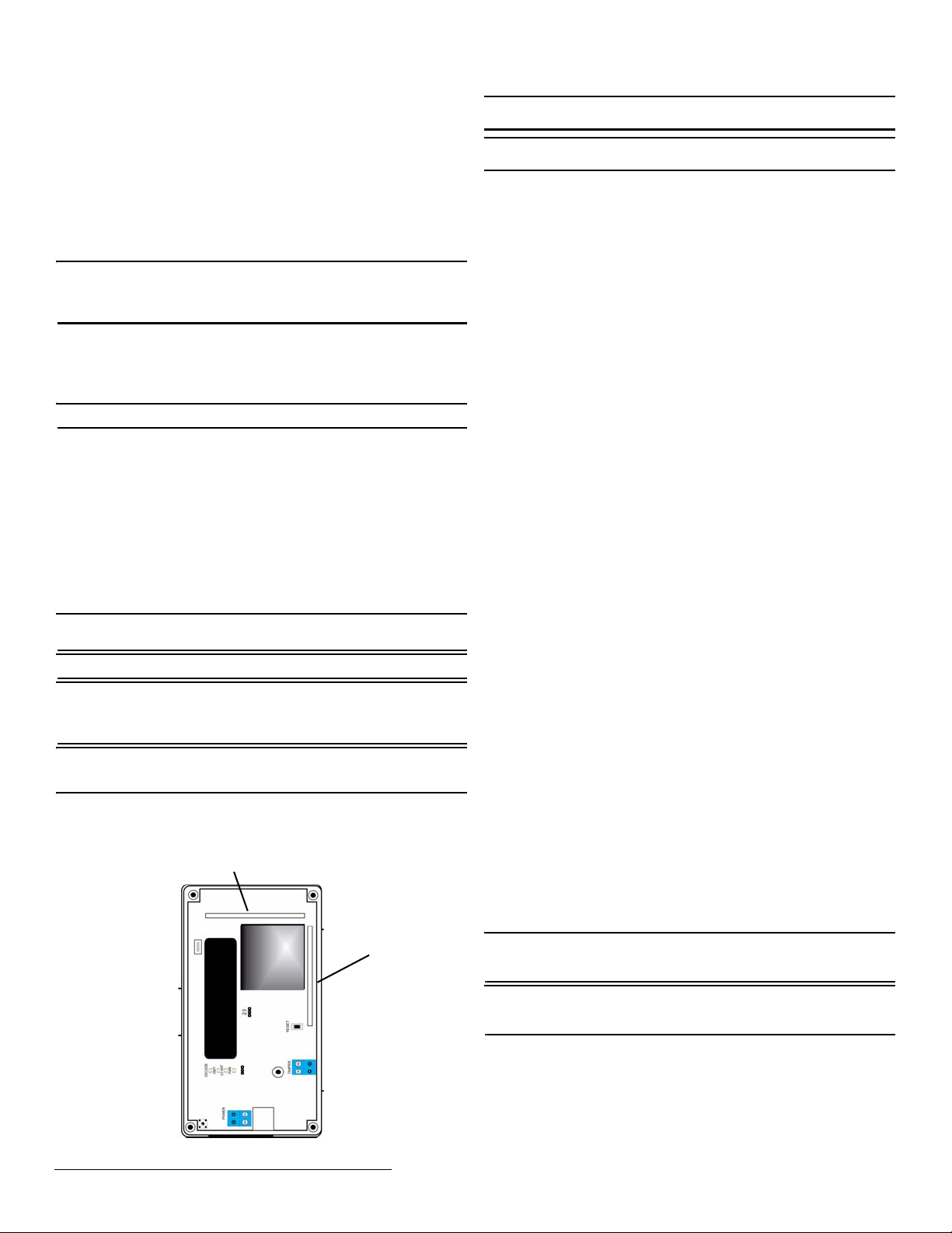
2.7 Mount the High Power Repeater
For best results, you will want to mount the high power repeater vertically,
so that the antennae are oriented as shown in Figure 3.
Caution: Mount the high power repeater in a location removed from metal.
Metal objects (duct work, wire mesh screens, boxes) will reduce RF range.
Caution: In UL 2560 installations, the unit must be mounted with the cable
opening facing downward as shown in Figure 3.
7. Use the provided anchors and screws to mount the high power repeater
in a location accessible for future maintenance.
• In large installations, high power repeaters should be mounted so that
every transmitter has multiple transmission paths to the EN6080 area
control gateway. This kind of redundancy preserves system integrity in
the event of temporary interruptions of any transmission path in the
system.
• For maximum efficiency, high power repeaters should be mounted
with as few obstacles as possible between them and the EN6080 area
control gateway.
• Always perform a walk test after mounting, activating each transmitter
assigned to the high power repeater and ensuring an appropriate
response.
2.8 Enable the Wall Tamper
The wall tamper must be enabled. If the high power repeater is removed
from the wall, the cutout on the back of the housing will detach, activating a
tamper alarm. To enable the wall tamper.
8. Attach one of the mounting screws to the wall through the tamper
mounting hole (Figure 2).
2.9 Close the Housing
The housing must be closed and the tamper spring in place to ensure the
security of your system.
9. Check that the tamper spring is in place and makes contact with the
high power repeater housing.
10. Close the housing.
3 US Patent Numbers
• 7,154,866
• 7,554,932
• 7,746,804
• Other patents pending
4 Specifications
Housing: 6.5" x 3.5" x 1" (165 mm x 89 mm x 25 mm)
Weight: 7.14 oz (204 g)
Operating environment: All UL installations: 32 to 140°F (0 to 60°C), 90%
relative humidity, non-condensing; all other installations: -4 to 140°F (-20 to
60°C), 90% relative humidity, non-condensing
Power requirement: 14 VAC, 60 Hz, 250 mA
Battery capacity: 3.6 VDC nominal, 2900 mAh
Typical back-up battery life: 24 hours
Operating frequency: 915-928 MHz (Australia), 921-928 MHz (New
Zealand), 902-928 MHz (USA)
Battery charger operating environment: 32 to 140°F (0 to 60°C), 90%
relative humidity, noncondensing
Accessories: ACC650: weatherproof plastic enclosure for outdoor
installations; BAT850: replacement lithium-ion battery assembly
UL certifications for EN5040-T: UL 365, UL 636, UL 1023, ULC/ORD-
C1023-74, UL 1076, UL 1610
UL certifications for EN5040-20T: UL 2560 (see conditions below)
Note: For UL 2560 installations, Inovonics repeaters must have 20 minute
check-in times. Inovonics transmitters must have a minimum of 60 minute
check-in times.
Note: For UL 2560 installations, the EN5040-20T high power repeater may
be used with completed emergency call systems for assisted living and
independent living facilities
Figure 3 High power repeater antenna orientation
1.23.14 05066N © Inovonics, 2014 - www.inovonics.com 2
For UL 2560 certified system installations, the following Inovonics
EchoStream devices are approved for installation within maximum system
configuration limits defined in section 1.1 of this document:
• EN6080 area control gateway
• EN5040-20T high power repeater
• End devices (transmitters) with a minimum 60-minute check-in
interval, as follows:
 Loading...