

Inovonics EN4204R User Manual
EN4204R Four Zone Add-On Receiver with
A
B
D
E
F
G
C
H
I
Relay Outputs
Installation Instructions
1 Overview
The EN4204R four zone add-on receiver with relay outputs allows you to
add up to four transmitters to any application. With diversity reception and
advanced signal processing, Inovonics’ EchoStream technology is
designed to minimize dead spots in transmission areas.
1.1 Installing an Inovonics Security System
An EchoStream survey kit should be used to establish an EchoStream
system. The EchoStream survey kit measures the signal strength of highpower repeater and sensor messages to help optimize your EchoStream
system.
Figure 1 Sample EchoStream system
The EchoStream survey kit provides you with two signal strength
measurements: signal level and signal margin.
Signal level
The signal level is the measurement of the overall decibel level of the
message.
Signal margin
The signal margin is the measurement of the decibel level of the message,
minus the decibel level of any interfering signals. Inovonics equipment
should be placed within a facility such that all end-devices produce signal
margin readings of at least 4 decibels.
Both the signal level and signal margin are measured in decibels. Because
signal strength and signal margin are measured on a logarithmic scale, the
difference between a decibel level of 3 (Weak) and a decibel level of 4
(Good) is a much larger difference than it would be on a linear scale.
Note: For more information about the EchoStream survey kit, see the
EN/EE7016SK EchoStream
Manual.
® Survey Kit Installation and Operation
1.3 EN4204R Four Zone Add-On Receiver with Relay
Outputs Front Panel
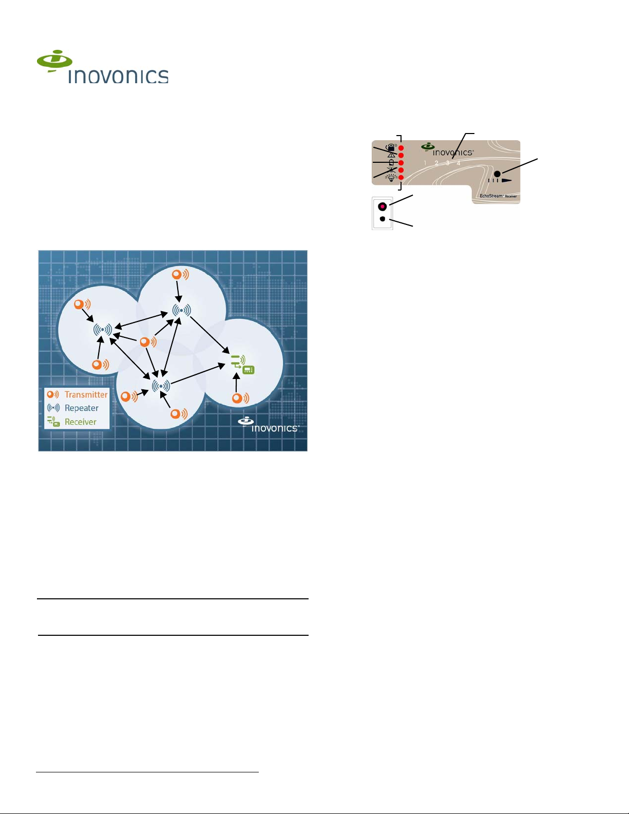
Figure 2 EN4204R Receiver LEDs and buttons
A Alarm LED B Tamper Fault LED C Low Battery Fault LED
D Inactive Fault LED E Power LED F Transmitter Number LEDs
G Advance Button H Decode LED I Reset Button
1.4 EN4204R Four Zone Add-On Receiver with Relay
Outputs LEDs
Most of the LEDs and buttons perform different function depending on
which mode the the receiver is in. By default the LEDs are in operation
mode; to enter diagnostic mode, press the advance button.
Operation LEDs
Alarm LED: Lights when any transmitter is sending an alarm transmission.
Tamper Fault LED: Lights when any transmitter is sending a tamper
transmission.
Low Battery Fault LED: Lit when any transmitter has a low battery.
Inactive Fault LED: Lit when any transmitter is inactive.
Power LED: Lit when receiving power.
Transmitter Number LEDs: Lit when the transmitter is in alarm.
Decode LED: Flashes when any recognizable transmission is received.
This LED is only visible when the pry-out door or cover is removed.
Diagnostic LEDs
Alarm LED: Lights when the selected transmitter is sending an alarm
transmission.
Tamper Fault LED: Lights when the selected transmitter is sending a
tamper transmission.
Low Battery Fault LED: Lit when the selected transmitter has a low battery.
Inactive Fault LED: Lit when the selected transmitter is inactive.
Power LED: Lit when receiving power.
Transmitter Number LEDs: Shows status of the transmitter assigned to that
number when lit. Use the advance button to scroll through transmitters.
Advance Button: Scrolls through transmitters to display status.
Decode LED: Flashes when any recognizable transmission is received.
This LED is only visible when the pry-out door or cover is removed.
1.2 Inovonics Wireless Contact Information
If you have any problems with this procedure, contact Inovonics Wireless
technical services:
• E-mail: support@inovonics.com.
• Phone: (800) 782-2709; (303) 939-9336.
7.24.14 05617D © Inovonics, 2014 - www.inovonics.com
1.5 EN4204R Internal Components
A
B
C
D
I
J
H
L
E
A
A
M
F
K
G
Delete
Out Type
Output
Sup Wind
Switch
F
Toggle
4h
Latch
96h
Follow
None
N/O
Moment
2h
N/C
12
3
4
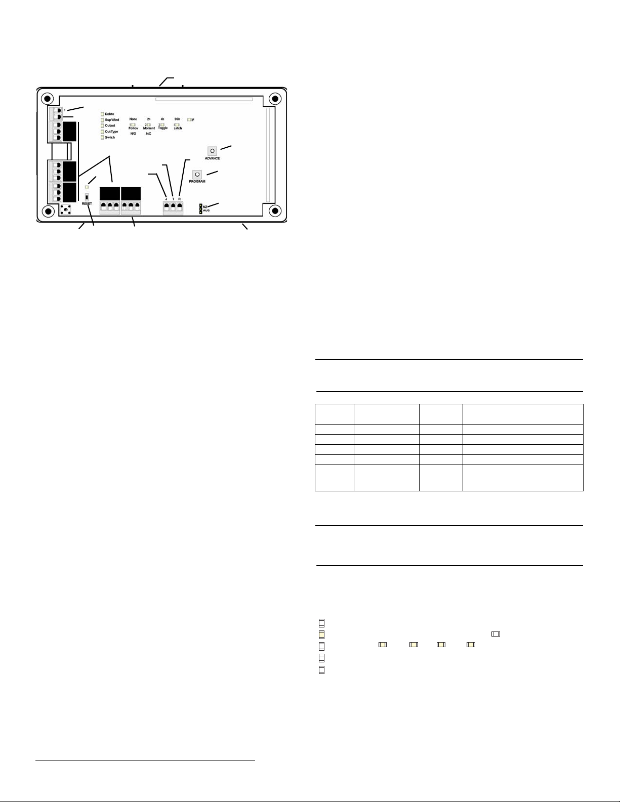
Figure 3 EN4204R internal components
A Housing release
tabs
D Output terminals E Fault output F Advance button
G Reset button H Reset input I Jam output
J Tamper output K Program button L Frequency band selection
M Decode LED
B Power (11-14
VDC)
C GND connection
pins
1.6 What’s in the Carton
• Two drywall anchors.
• Two mounting screws.
• Three housing screws.
• Two pieces double-sided mounting tape.
• One frequency band selection jumper.
2 Installation and Startup
2.1 Installation Notes
• These products are designed to be maintained by professional
security technicians.
• Products are tested for indoor use.
• All products should be manually tested weekly.
2.2 Connect Power Cabling
Before beginning startup, you will have to connect power to the receiver. To
connect power to the receiver:
1. Use a small screwdriver to press the housing release tab on the top or
bottom of the receiver; separate the housing.
2. Connect power cabling to the Power and GND connections.
• Power source should be 11-14 VDC. Power supply must be
unswitched, uninterrupted, and regulated.
2.3 Select the Frequency Band
EchoStream devices are able to use a range of radio frequencies, and must
be configured for your geographic area. This device ships with a default
frequency range of 902-928 MHz for use in North America. If you are using
the device in North America, skip to section 3, “Registering a Transmitter”;
if you are using the device in Australia or New Zealand, you will need to
configure it.
1. Place a selection jumper on the appropriate frequency band selection
pins.
• Place the jumper on the top two pins, marked NZ, to set the frequency
range to 921-928 MHz for New Zealand.
• Place the jumper on the bottom two pins, marked AUS, to set the
frequency range to 915-928 MHz for Australia.
2. Cycle power source to reset.
3 Registering a Transmitter
3.1 Quick Setup
In many cases, the default settings are sufficient and the points don’t need
programming changes. To register transmitters without changing the
settings:
First Transmitter
1. Press the advance button one time to select the first point.
2. Press the program button four times to select the default programming
options.
3. The first point number will be flashing, indicating it is awaiting the
transmitter’s reset message; press the transmitter’s reset button.
Second Transmitter
1. Press the advance button two times to select the second point.
2. Press the program button four times to select the default programming
options.
3. The second point number will be flashing, indicating it is awaiting the
transmitter’s reset message; press the transmitter’s reset button.
Third Transmitter
1. Press the advance button three times to select the third point.
2. Press the program button four times to select the default programming
options.
3. The third point number will be flashing, indicating it is awaiting the
transmitter’s reset message; press the transmitter’s reset button.
Fourth Transmitter
1. Press the advance button four times to select the fourth point.
2. Press the program button four times to select the default programming
options.
3. The fourth point number will be flashing, indicating it is awaiting the
transmitter’s reset message; press the transmitter’s reset button.
Note: After registering a transmitter, there is no need to exit programming
mode. The receiver is normal operation once the transmitter’s reset button
has been pressed.
The default settings are:
Point Supervision
Window
1 4 hours 1 Follow
2 4 hours 2 Follow
3 4 hours 3 Follow
4 4 hours 4 Follow
F N/A Fault Inactive is set to follow; low
3.2 Customize Transmitters
If the default settings are not sufficient, you will need to program the points
individually.
Note: If changing programming for a point that already has a transmitter
registered to it, there is no need to re-register the transmitter. Changes to
point programming are automatically assigned to the transmitter registered
to that point.
The following programming options available:
Supervision window
• None, 2h, 4h, or 96h. When you are choosing the supervision window,
the “Sup Wind” LED will light, along with the LED that indicates the
selected window.
Figure 4 Select the supervision window
Output Type
battery and tamper are set to
latching.
7.24.14 05617D © Inovonics, 2014 - www.inovonics.com 2
 Loading...