

EE1941/EN1941 One-Way Binary RF Module
B
C
G
D
I
J
E
F
K
L
M
N
H
A
O
B
C
G
D
I
J
E
F
K
L
M
N
H
A
O
Installation and Operation Manual - 06287E
1 Overview
EchoStream RF modules are designed to be easily interfaced with your
electronic remote application controller (RAC). RF modules allow the
assimilation of any user-specific application into an EchoStream system.
Once integrated with existing products, RF modules provide you with
complete EchoStream functionality.
E*1941 one-way binary RF modules are end-devices that use a logic-level
connection to interface with your RAC. E*1941 one-way binary RF modules
can be used in either one-way or two-way EchoStream systems.
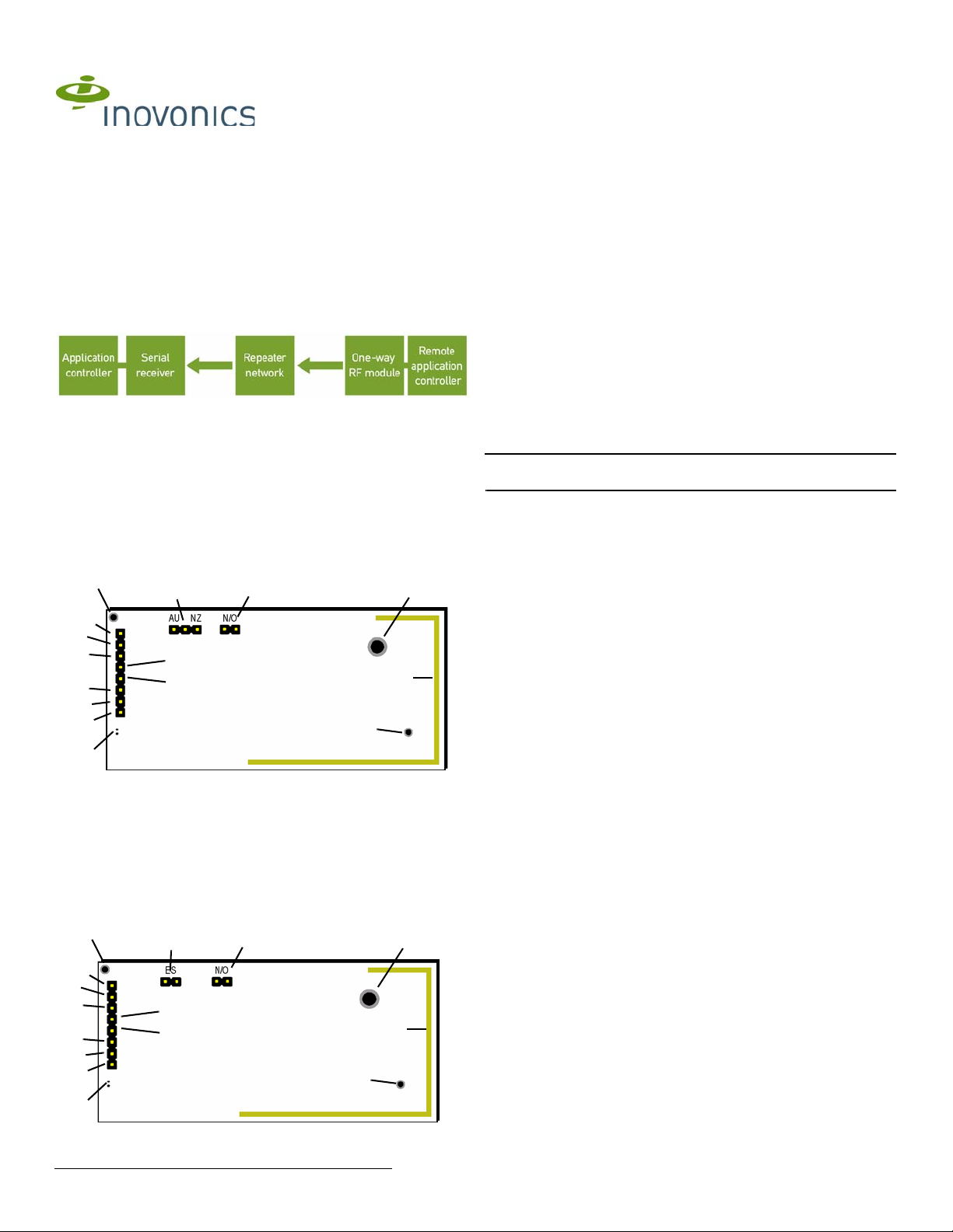
Figure 1 One-Way System Components
2 One-Way Binary RF Module Components
The E*1941 is a universal one-way binary RF module with two alarm input
pins, allowing the use of dual inputs. Input one is the primary alarm, bit 0;
input two is the secondary alarm, bit 1.
There are two models in the E*1941 product family.
• The EN1941, for 900 MHz applications in North America, New
Zealand, and Australia,
• The EE1941, for 868 MHz applications in Europe
A Board stabilization hole. B Reserved C Reserved
D Secondary alarm E Power F Ground
G Primary alarm H LED contacts I Tamper input
J Reset input K ES selection pins L N/O selection pins
M Mounting hole N On-board antenna O Board stabilization
Frequency band selection pins (EN1941 only) Place a jumper to select the
frequency band for your geographic area.
• Place the jumper on the left two pins to select 915-928 MHz for
Australia.
• Place the jumper on the right two pins to select 921-928 MHz for New
Zealand.
• Leave the jumper off the pins to select 902-928 MHz for North
America.
ES selection pins (EE1941 only) To enable compatibility with ES products,
place a selection jumper on the ES selection pins; if no ES products are
used in your system, remove the selection jumper.
N/O selection pins Place a jumper to select normally open inputs; remove
the jumper to select normally closed.
Note: The E*1941 is shipped with the jumper unattached. With the jumper
unattached, the E*1941 defaults to normally closed.
Secondary alarm Connects a secondary end-device to provide RF alarm
data for any user-specific application.
Primary alarm Connects a primary end-device to provide RF alarm data for
any user-specific application.
Tamper input Connects a tamper input to send a message when userspecific end-device is tampered with.
Reset input Connects a reset input to reset the one-way binary RF module
after a frequency band selection change or N/O - N/C selection change,
and to initiate an RF transmission.
Power Connect power cabling to an external power supply of 2.4 to 5.5
volts.
Ground Connects to ground.
Mounting hole Used to mount the one-way binary RF module to the user-
specific product. The mounting hole should only be used with a nylon
standoff, never metal.
LED contacts Use to control an LED switch. Not designed to drive LED
power.
Board stabilization holes Used to mount and stabilize the board. The board
stabilization holes should only be used with non-metal standoffs.
hole
Figure 2 EN1941 One-Way Binary RF Module Components
A Board stabilization hole. B Reserved C Reserved
D Secondary alarm E Power F Ground
G Primary alarm H LED contacts I Tamper input
J Reset input K Frequency band
M Mounting hole N On-board antenna O Board stabilization
Figure 3 EE1941 One-Way Binary RF Module Components
4.9.13 06287E © Inovonics, 2013 - www.inovonics.com
selection pins
L N/O selection pins
hole
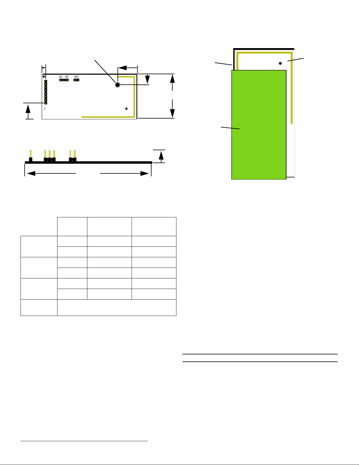
3 One-Way Binary RF Module Dimensions
1.3”
Pitch:
2.54mm.
.385” to
Center of
First Pin
.090” to
Center
of First
Pin
.335” to
Center
of Hole
.515” to
Center of
Hole
.156”
Diameter
.5”
2.525”
End user
application
printed circuit
board
RF
module
Clear transmit
region in front
and back of
antenna
J The RF module should be integrated so the antenna is unobstructed by
the end user’s PCB, batteries, or any other conductive material.
Figure 4 E*1941 One-Way Binary RF Module Dimensions
4 One-Way Binary RF Module Connections and
Output Jumpers
ConnectionOutput Jumper
N/O
Primary
Alarm
Secondary
Alarm
Tamper
Reset
5 Installation
A Connecting the One-Way Binary RF Module
B One-way binary RF modules are designed to be easily interfaced with
your electronic remote application controller, however integration must
conform to the following:
C The RF module must only be connected at the eight pin header or eight
pin plated thru-holes.
D All cables and wires must be routed away from the component side of
the RF module.
E The integrated antenna must not be tampered with; no connection to an
alternate antenna is provided.
F The application module must not include an integrated secondary
colocated radio module.
G The one-way binary RF module antenna should be placed so that it is
facing away, or otherwise isolated from, your device’s ground plane.
H Components that are sensitive to RF transmission, such as high gain
circuits, should be isolated from the antenna to prevent interference.
I One-way binary RF modules should not be mounted on metal surfaces
or inside metal enclosures. They should also not be mounted where
sheet metal ductwork, wire mesh screens, etc. might block
transmissions.
Open Alarm Clear Alarm
Ground Alarm Alarm Clear
Open Alarm Clear Alarm
Ground Alarm Alarm Clear
Open Alarm Alarm
Ground Alarm Clear Alarm Clear
Open for normal operation; connect to the ground and
release for a board reset.
Output Jumper
N/C
Figure 5 The RF module should be integrated so the antenna is
unobstructed
6 One-Way Binary RF Module Requirements
6.1 Power Requirements
The E*1941 has an on-board voltage regulator. Connect power cabling to
an external power supply (Vcc) of 2.4 to 5.5 volts. Voltage must be
sustained at 2.4 volts or above and supply 100 milliamps during the
transmit cycle.
6.2 EN1941
Assuming check-in messages every 3 minutes and infrequent alarm
messages (one per day, on average), the average current draw is 32 uA.
Peak current draw while transmitting is less than 100 mA. One alarm/
restore cycle per hour results in about 5.3 uA increase in average current.
6.3 EE1941
Assuming check-in messages every 12 minutes and infrequent alarm
messages (one per day, on average), the average current draw is 15 uA.
Peak current draw while transmitting is less than 50 mA. One alarm/restore
cycle per hour results in about 5.3 uA increase in average current.
6.4 Low Battery Condition
The E*1941 measures battery voltage every three and a half hours, and,
when the battery measures 2.4 volts, a serial message is sent indicating a
low battery condition.
6.5 Temperature range
-40°C to +66°C, non-condensing
6.6 RF network compatibility
EchoStream Commercial Mesh Network
6.7 Input Requirements
Caution: Input levels must not exceed 3.3 V.
Open When an active source (open collector or dry contact) is used to drive
the alarm or tamper input, the voltage should be between 0.75xVcc and
Vcc. A passive input should have an impedance of greater than 5.1k ohm
between the input and ground.
Closed When an active source is used, the voltage should be less than
0.25xVcc. A passive input should have an impedance of less than 240
ohm.
6.8 LED Requirements
The LED output is an active output from the microprocessor, with a 1k
series resistor to limit current draw. Default state is low, and the LED pin is
pulled high during transmit.
4.9.13 06287E © Inovonics, 2013 - www.inovonics.com 2
 Loading...