

InnoSenT IVS 234 User Manual
InnoSenT sets standards – worldwide
User Manual IVS-234
Version 6.3 - 01.02.2018
Product Family
Applications
Additional Information
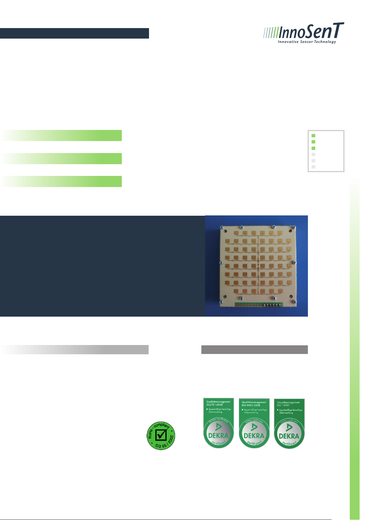
PLL stabilized K-Band VCO Transceiver
True Speed over Ground measurement
Customer specific product for DEUTA-WERKE GmbH
DEUTA-WERKE GmbH has to be informed about all technical changes.
Features:
» K-Band Transceiver
» CW (continuous wave) mode
» stereo (dual channel) operation for direction-of-motion
identification
» integrated PLL circuit for high frequency stability
» programmable transmitter frequency
» balanced mixer with reduced common mode noise for
both channels (DOP and QDOP)
Movement
Velocity
Direction
Presence
Distance
Angle
Description Certificates
The IVS-234 is a MMIC based CW K-Band
Transceiver with an integrated PLL-circuit
for high frequency stability.
The PLL-circuit enables the customer to
program its own transmit frequencies
directly via SPI-Bus.
This product is compliant to the restriction of hazardous substances
(RoHS - European Union direc-
tive 2011/65/EU)
CONFIDENTIAL AND PROPRIETARY
The information contained in this document shall remain the sole and exclusive property of InnoSenT GmbH
and shall not be disclosed by the recipient to third parties without prior consent of InnoSenT in writing.
InnoSenT GmbH has established and applies a quality system for: Development,
production and sales of radar sensors for
industrial and automotive sensors.
Page 1 Version 6.3 USER MANUAL IVS-234

InnoSenT sets standards – worldwide
Electrical Characteristics
Parameter Symbol Min. Typ. Max. Units Comment
Oscillator
transmit frequencies F
temperature drift (frequency) |Δf| 10 30 kHz/°K
1
24.008 24.243 GHz can be adjusted by user
(1)
output power (EIRP) P
out
20 dBm
Receiver (compare with amplifier circuit on page 4)
IF-amplifier bandwidth 10 - 1M Hz
gain 46 dB
I/Q balance amplitude 6 dB
phase 70 110 ° reject criteria
offset
reject criteria offset v_offset
v_offset
Q(QDOP)
-500 500 mV @ InnoSenT test setup
I(DOP)
-500 500 mV @ InnoSenT test setup
signal level
reject criteria signal level S
S
Q(QDOP)
I(DOP)
45 64 83 mV @ InnoSenT test setup
45 64 83 mV @ InnoSenT test setup
noise level
reject criteria noise level R
(1)
The user is responsible for the compliance of the transmit frequency!
(2)
measured during end of line test according to InnoSenT instruction manual AA 7-7-29
R
Q(QDOP)
I(DOP)
10 18 mV
10 18 mV
@ InnoSenT test setup
RMS
@ InnoSenT test setup
RMS
(2)
(2)
(2)
(2)
(2)
(2)
Power supply
supply voltage V
supply current I
refractory period
(1)
cc
V
SS
CC
I
SS
4.75 5.25 V
-5.25 -4.75 V
150 200 mA
20 50 mA
1 s
Antenna pattern (compare with antenna plot on page 4)
full beamwidth @ -3dB horizontal 11 13 15 °
vertical 11 13 15 °
side-lobe suppression horizontal 12 dB
vertical 12 dB
(1)
time between shut down and restart
CONFIDENTIAL AND PROPRIETARY
The information contained in this document shall remain the sole and exclusive property of InnoSenT GmbH
and shall not be disclosed by the recipient to third parties without prior consent of InnoSenT in writing.
Page 2 Version 6.3 USER MANUAL IVS-234
 Loading...