

Page 1
Form MHD56012
PARTS, OPERATION AND MAINTENANCE MANUAL
for
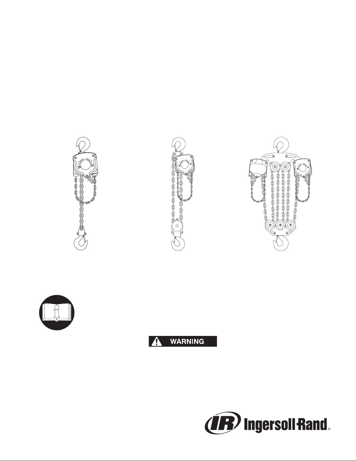
MANUAL CHAIN HOIST MODELS
VL2-005 VL2-010 VL2-015 VL2-020 VL2-030
1/2 ton 1 ton 1-1/2 ton 2 ton 3 ton
VL2-050 VL2-080 VL2-100 VL2-150 VL2-200
5 ton 8 ton 10 ton 15 ton 20 ton
Including S•COR•E (Spark and Corrosion Resistant) Features
Unless otherwise noted, tons in this manual are metric tons (2,200 lbs.)
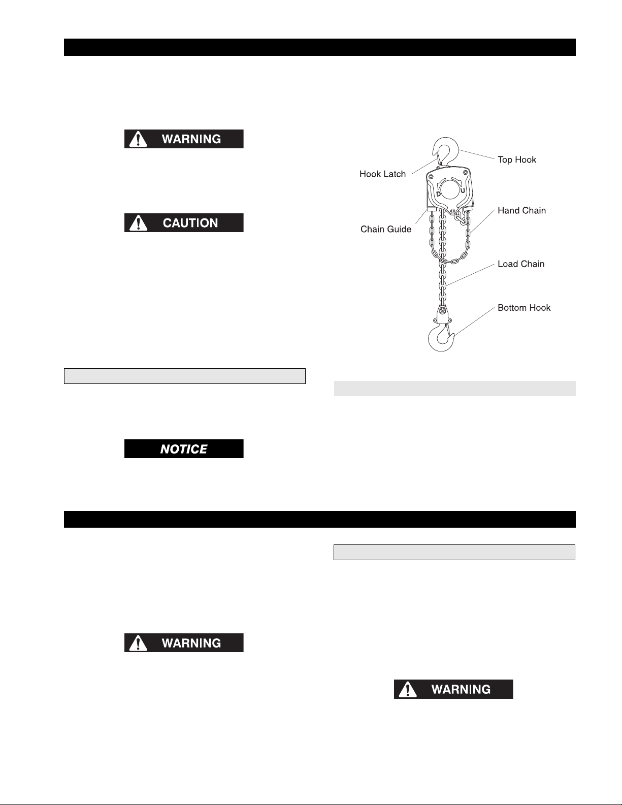
(Dwg. MHP0037)
1/2, 1, 1-1/2 and 2 ton
READ THIS MANUAL BEFORE USING THESE PRODUCTS. This manual
contains important safety, installation, operation and maintenance
information. Make this manual available to all persons responsible for the
installation, operation and maintenance of these products.
Do not use this hoist for lifting, supporting, or transporting people or lifting or
supporting loads over people.
Always operate, inspect and maintain this hoist in accordance with American National
Standards Institute Safety Code (ASME B30.16) and any other applicable safety codes
and regulations.
Form MHD56012
Edition 8
July 2004
71116107
© 2004 Ingersoll-Rand Company
(Dwg. MHP0038)
3 and 5 ton
(Dwg. MHP0039)
15 ton
Page 2
SAFETY INFORMATION
This manual provides important information for all personnel
involved with the safe installation, operation and proper
maintenance of this product. Even if you feel you are familiar with
this or similar equipment, you should read this manual before
operating the product.
Danger, Warning, Caution and Notice
Throughout this manual there are steps and procedures which, if
not followed, may result in a hazard. The following signal words
are used to identify the level of potential hazard.
Indicates an imminently
hazardous situation which, if not
avoided, will result in death or
serious injury.
Indicates a potentially hazardous
situation which, if not avoided,
could result in death or serious
injury.
Indicates a potentially hazardous
situation which, if not avoided,
may result in minor or moderate
injury or property damage.
Indicates information or a
company policy that relates
directly or indirectly to the
safety of personnel or protection
of property.
The National Safety Council, Accident Prevention Manual for
Industrial Operations, Eighth Edition and other recognized safety
sources make a common point: Employees who work near cranes
or assist in hooking on or arranging a load should be instructed to
keep out from under the load. From a safety standpoint, one factor
is paramount: conduct all lifting operations in such a manner that
if there were an equipment failure, no personnel would be injured.
This means keep out from under a raised load and keep out of the
line of force of any load.
The Occupational Safety and Health Act of 1970 generally places
the burden of compliance with the user, not the manufacturer.
Many OSHA requirements are not concerned or connected with
the manufactured product but are, rather, connected with the final
installation. It is the owner’s and user’s responsibility to determine
the suitability of a product for any particular use. It is
recommended that all applicable industry, trade association,
federal, state and local regulations be checked. Read all operating
instructions and warnings before operation.
Rigging: It is the responsibility of the operator to exercise caution,
use common sense and be familiar with proper rigging techniques.
Refer to ASME B30.9 for rigging information, American Society
of Mechanical Engineers, Three Park Avenue, New York, NY
10016.
Safety Summary
• Do not use this hoist for lifting, supporting, or transporting
people or lifting or supporting loads over people.
• Hoists are designed to provide a 4 to 1 safety factor.
Supporting structures and load-attaching devices used in
conjunction with this hoist must provide an adequate safety
factor to handle the rated load, plus the weight of the hoist and
attached equipment. This is the customer’s responsibility. If in
doubt, consult a registered structural engineer.
Ingersoll-Rand hoists are manufactured in accordance with the
latest ASME B30.16 standards.
2 MHD56012 - Edition 8
Page 3
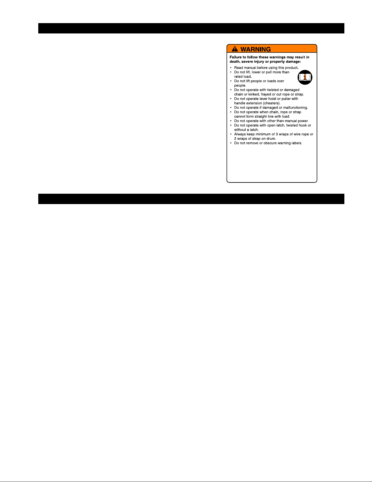
WARNING TAG
Each hoist is supplied from the factory with the warning tag
shown. If tag is not attached to your unit, order a new tag and
install it. Refer to the parts list for the part number. Read and obey
all warnings and other safety information attached to this hoist.
Tag may be shown smaller than actual size.
SAFE OPERATING INSTRUCTIONS
The following warnings and operating instructions have been
adapted in part from American National Standard ASME B30.16
and are intended to avoid unsafe operating practices which might
lead to injury or property damage.
Ingersoll-Rand recognizes that most companies who use hoists
have a safety program in force in their plants. In the event that
some conflict exists between a rule set forth in this publication and
a similar rule already set by an individual company, the more
stringent of the two should take precedence.
Safe Operating Instructions are provided to make an operator
aware of dangerous practices to avoid and are not necessarily
limited to the following list. Refer to specific sections in the
manual for additional safety information.
1. Only allow personnel trained in safety and operation to
operate hoist.
2. Only operate a hoist if you are physically fit to do so.
3. When a “DO NOT OPERATE” sign is placed on hoist, do
not operate hoist until sign has been removed by designated
personnel.
4. Before each shift, the operator should inspect hoist for wear
or damage.
5. Never use a hoist which inspection indicates is worn or
damaged.
6. Periodically, inspect hoist thoroughly and replace worn or
damaged parts. Refer to “INSPECTION” section.
7. Lubricate hoist regularly. Refer to “LUBRICATION”
section.
8. Do not use hoist if hook latch has been sprung or broken.
9. Check that hook latches are engaged before using.
10. Never splice a hoist chain by inserting a bolt between links.
11. Only lift loads less than or equal to rated capacity of hoist.
Refer to “SPECIFICATIONS” section.
12. Never use the hoist chain as a sling.
13. Never operate a hoist when load is not centered under top
hook. Do not “side pull” or “yard.”
14. Never operate a hoist with twisted, kinked, “capsized” or
damaged load chain.
15. Do not force a chain or hook into place by hammering.
16. Never insert point of hook into a chain link.
17. Be certain load is properly seated in saddle of hook, and hook
latch is engaged.
18. Do not support load on tip of hook.
19. Never run load chain over a sharp edge. Use a sheave.
20. When using two hoists to suspend one load, select two hoists
each having a rated capacity equal to or more than the load.
This provides adequate safety in the event of a sudden load
shift.
21. Pay attention to the load at all times when operating hoist.
22. Always ensure that you, and all other people, are clear of load
path. Do not lift a load over people.
23. Never use hoist for lifting or lowering people, and never
allow anyone to stand on a suspended load.
24. Ease slack out of chain and sling when starting a lift. Do not
jerk load.
25. Do not swing a suspended load.
26. Do not leave a load suspended when hoist is unattended or
not in use.
27. Never weld or cut a load suspended by the hoist.
28. Never use hoist chain as a welding electrode.
29. Do not operate hoist if chain jumping, excessive noise,
jamming, overloading or binding occurs.
30. Keep load from hitting load chain.
31. Only operate the hoist with manual power.
32. After use, or when in a non-operational mode, hoist should be
secured against unauthorized and unwarranted use.
MHD56012 - Edition 8 3
Page 4
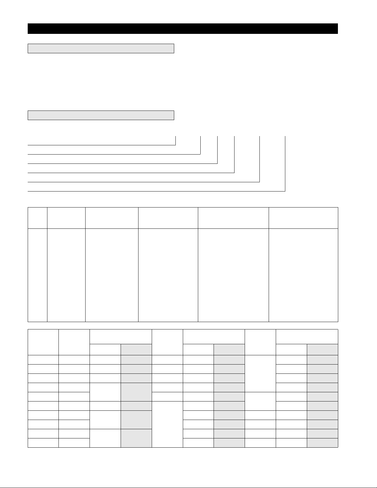
SPECIFICATIONS
General
The VL2 Manual Chain Hoist can be mounted to the suspension
shaft of a trolley or a permanent mounting structure. The hoist is
designed to lift and lower loads up to rated capacity with minimal
effort.
To determine your hoist configuration refer to the capacity and
serial number nameplate for serial and model number information.
Model Code Explanation
Model Code Example: VL2-050-10-8V VL2 - 050 - 10 - 8 V
Series
Hoist Capacity
S•COR•E
Lift
Hand Chain Drop
Options
Series
VL2 = 005, 010,
Model No.
VL2-005 1/2 55
VL2-010 1 73
VL2-015 1-1/2 74
VL2-020 2
VL2-030 3 7.1 x 21.2 112
VL2-050 5 85
VL2-080 8
VL2-100 10 362
VL2-150 15
VL2-200 20 2 x 362
* One metric ton equals 2200 lbs.
Hoist
Capacity
015, 020,
030, 050,
080, 100,
150 and 200
Rated
Capacity
metric
tons*
S•COR•E
- = Standard
CP = Copper Plated
SB = Solid Bronze
Pull to lift rated load Load
lb
76 34.5
90 40.9
2 x 90 2 x 41
(Hoist load chain/hook
10 = Hook travel, 10
XX = Specify length
kg ft mlbkg
25.0 5.0 x 15 25 7.6
33.2 6.3 x 19.2 28 8.5 36 16.4
33.6 7.1 x 21.2 57 17.4 45 20.4
38.6
Lift:
travel)
std, 15 and 20 ft.
Hand Chain O’Hauled
Chain size
(mm)
8.0 x 24.2 73
9.0 x 27.2
to lift load 1 ft (0.3 m) No. of
2 x 272
181 55.2 94 42.6
272
Hand Chain Drop:
(Hand chain is 2 ft. (0.6 m)
less than lift)
8 = Lift 10 ft. chain drop
8 ft. (standard)
13 = Lift 15 ft. chain drop
13 ft.
18 = Lift 20 ft. chain drop
18 ft.
XX = Specify drop
chain falls
1
22.3 50 22.7
34.1
82.9 3 150 68.2
110.3 4 188 85.5
2 x 82.9 6 395 179.5
2 x 110 8 485 220.4
2
Options
V = Overload Clutch
(standard)
H = Zinc Plated hand chain
S•COR•E
N = Nickel plated load
chain S•COR•E
Z = Sand blast/carbozinc
P=Marine Grade
corrosion preventative
finish
S = Chain Container
(fabric)
-E = Meets European
Machinery Directives
H o i st N e t We i g h t
(std. 10 ft. lift)
20 9.0
52 23.6
4 MHD56012 - Edition 8
Page 5
INSTALLATION
Prior to installing hoist, carefully inspect it for possible shipping
damage. Hoists are supplied fully lubricated from the factory.
Lubrication of the load chain is recommended before initial hoist
operation.
• Depending on model selected, hoist may weigh up to 485 lbs.
(220 kg). If parts of the hoist are dropped, they can cause
injury, death or property damage. Adequately support hoist
during installation.
• Owners and users are advised to examine specific, local or
other regulations, including ASME standards and/or OSHA
Regulations which may apply to a particular type of use of this
product before installing or putting hoist to use.
The VL2 manual chain hoist must be used in a vertical position to
provide a straight line pull from top to bottom hook. The hoist
must be positioned so that it does not contact the support members
when in use. When operating in limited areas suitable lifting
attachments or slings must be used to prevent hoist body and hand
chain from being obstructed.
Initial Operating Checks
Operate hoist with a test load (10% of rated capacity) by raising
and lowering this load several times. Verify brake operation with
this light load prior to applying heavier loads.
Familiarize operators and personnel responsible for hoist
installation and service with ASME B30.16 specifications and this
manual prior to placing unit into service. All requirements of this
specification, including testing should be met before approving
hoist for operation.
(Dwg. MHP0436)
Installing Chain Container
Refer to Dwg. MHP0321 on page 19. Position chain container to
ensure minimum contact with handchain. On larger CC-8 and CC9 style chain containers which use S-Hooks to support chain
container, ensure hook ends are bent closed.
• Each time a load is lifted, the operation of the brake should
be checked by raising load slightly and stopping to ensure
brake will hold load before continuing to lift.
OPERATION
The four most important aspects of hoist operation are:
1. Follow all safety instructions when operating hoist.
2. Allow only personnel trained in safety and operation of this
hoist to operate hoist.
3. Subject each hoist to a regular inspection and maintenance
procedure.
4. Be aware of the hoist capacity and weight of load at all times.
• Hoist is not designed or suitable for lifting, lowering or
moving persons. Never lift loads over people.
Hoist Operation
When facing hand chain side of hoist:
Pull down on right hand chain (clockwise) to raise load.
Pull down on left hand chain (counterclockwise) to lower load.
On 15 and 20 ton hoists, use two operators, one on each of the two
hand chains. To keep the load chain centered in the block
assemblies, operate hoist units simultaneously and at the same
speed. An equal amount of unloaded chain must be maintained
under each hoist body.
• Do not allow load chain, on 15 and 20 ton hoists, to
accumulate on one side (under one hoist body). Excessive
loading to load chain anchor may occur resulting in a falling
load which can cause death, injury or property damage.
MHD56012 - Edition 8 5
Page 6

Storing the Hoist
• The clicking sound of the pawl on the ratchet gear is normal
when a load is being raised.
INSPECTION
• All new, altered or modified equipment should be inspected
and tested by personnel trained in safety, operation and
maintenance of this equipment to ensure safe operation at
rated specifications before placing equipment in service.
Frequent and periodic inspections should be performed on
equipment in regular service. Frequent inspections are visual
examinations performed by operators or service personnel and
include observations made during routine equipment operation.
Periodic inspections are thorough inspections conducted by
personnel trained in the safety, operation and maintenance of this
equipment. ASME B30.16 states inspection intervals depend upon
the nature of the critical components of the equipment and severity
of usage.
Careful inspection on a regular basis will reveal potentially
dangerous conditions while still in the early stages, allowing
corrective action to be taken before the condition becomes
dangerous.
Deficiencies revealed through inspection, or noted during
operation, must be reported to designated personnel trained in
safety, operation and maintenance of this equipment. A
determination as to whether a condition constitutes a safety hazard
must be decided, and the correction of noted safety hazards
accomplished and documented by written report before placing
the equipment in service.
Records and Reports
Inspection records, listing all points requiring periodic inspection
should be maintained for all load bearing equipment. Written
reports, based on severity of service, should be made on the
condition of critical parts as a method of documenting periodic
inspections. These reports should be dated, signed by the person
who performed the inspection, and kept on file where they are
readily available for review.
1. Always store hoist in a no load condition.
2. Wipe off all dirt and water.
3. Oil the chain, hook pins and hook latch pins.
4. Hang in a dry place.
5. Before returning hoist to service follow instructions for
Hoists not in Regular Service in “INSPECTION” section.
Load Chain Reports
Records should be maintained documenting the condition of load
chain removed from service as part of a long-range load chain
inspection program. Accurate records will establish a relationship
between visual observations noted during frequent inspections and
the actual condition of the load chain as determined by periodic
inspection methods.
Frequent Inspection
The Manual Chain Hoist should be inspected at the beginning of
each shift. Visual inspections should also be conducted during
regular service for any damage or evidence of malfunction which
appears between regular inspections.
1. OPERATION. Check for visual signs or abnormal noises
which could indicate a potential problem. Do not operate a
hoist unless the chain feeds through the hoist and hook block
smoothly. Listen for “clicking”, binding or malfunctioning.
The clicking sound of the pawl on the ratchet gear is normal
when a load is being raised. If chain binds, jumps, or is
excessively noisy, clean and lubricate the chain. If problem
persists, replace the chain. Do not operate the hoist until all
problems have been corrected. Check that hand chain moves
freely and without binding or excessive drag. Hook should
stop moving when hand chain stops moving.
2. HOOKS. Check for wear or damage, increased throat width,
bent shank or twisting of hook. Replace hooks that exceed
the throat opening discard width (15%) shown in Table 1
refer to Dwg. MHP0040 on page 6, or exceed a 10º twist
refer to Dwg. MHP0111 on page 7. If hook latch snaps past
tip of hook, hook is sprung and must be replaced. Check hook
support bearings for lubrication and damage. Check hooks
swivel easily and smoothly. Repair or lubricate as necessary.
• The external placement of coded marks on equipment
identifying completed inspections and operationally certified
equipment is an acceptable method of documenting periodic
inspections in place of written records.
6 MHD56012 - Edition 8
(Dwg. MHP0040)
Page 7
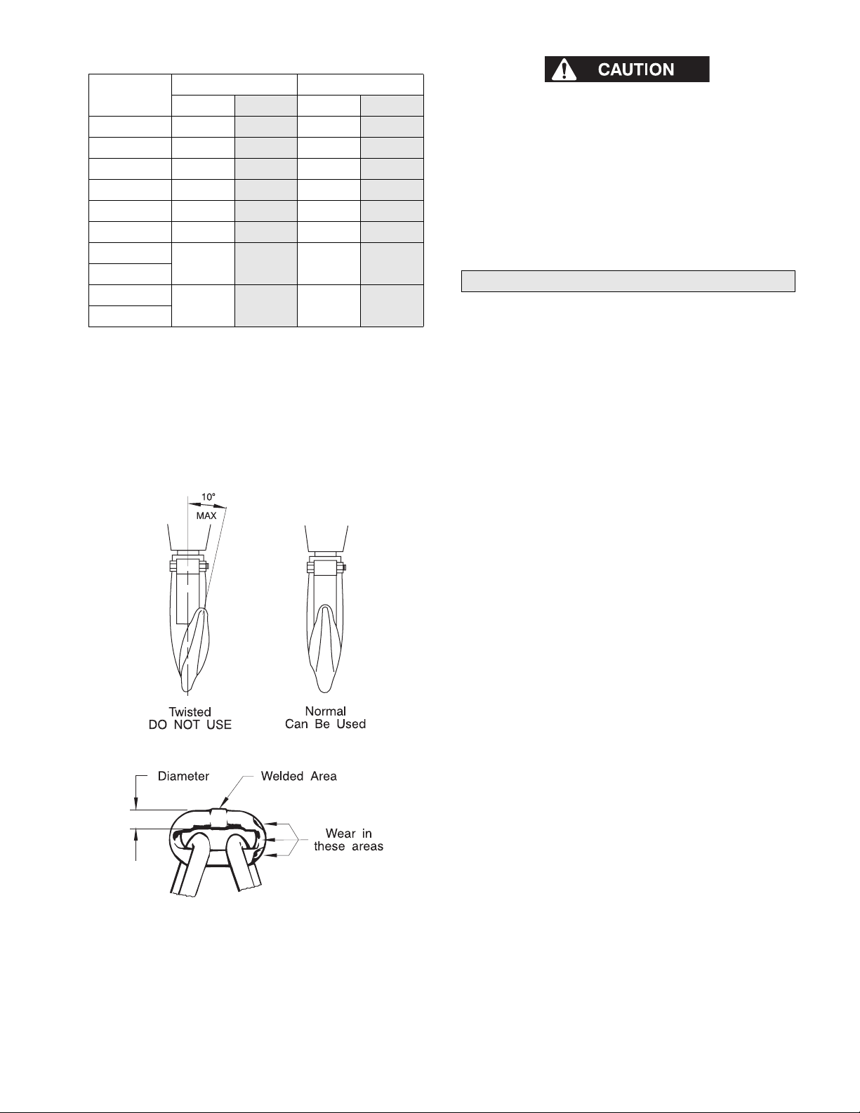
Table 1: Hook Throat Dimension
Model No.
VL2-005 1.22
VL2-010 1.33
VL2-015 1.5
VL2-020 1.61
VL2-030 1.85
VL2-050 2.01
VL2-080
VL2-100
VL2-150
VL2-200
Throat Width Discard Width
in.
2.8 71 3.21 81.6
3.54
mm in. mm
31 1.4 35.6
34 1.54 39.1
38 1.72 43.7
41 1.86 47.2
47 2.12 54
51 2.31 58.6
90 4.07 103.5
• The full extent of chain wear cannot be determined by visual
inspection. At any indication of chain wear inspect chain and
load sheave in accordance with instructions in “Periodic
Inspection.”
• A worn load chain may cause damage to load sheave. Inspect
load sheave and replace if damaged or worn.
5. LOAD CHAIN REEVING. Refer to Dwg. MHP0042 on
page 9. Make sure welds on standing links are away from
load sheave. Reinstall chain if necessary. Make sure chain is
not capsized, twisted or kinked. Adjust as required.
Periodic Inspection
According to ASME B30.16, frequency of periodic inspection
depends on the severity of usage:
3. HOOK LATCHES. Check operation of hook latches. Replace
if broken or missing.
4. CHAIN. Refer to Dwg. MHP0102 on page 7. Examine each
link for bending, cracks in weld areas or shoulders, transverse
nicks and gouges, weld splatter, corrosion pits, striation
(minute parallel lines) and chain wear, including bearing
surfaces between chain links. Replace a chain that fails any of
the inspections. Check lubrication and lubricate if necessary.
Refer to “Load Chain” in “LUBRICATION” section.
(Dwg. MHP0111)
(Dwg. MHP0102)
NORMAL HEAVY SEVERE
yearly semiannually quarterly
Disassembly may be required for HEAVY or SEVERE usage.
Keep accumulative records of periodic inspections to provide a
basis for continuing evaluation. Inspect all items in “Frequent
Inspection.” Also inspect the following:
1. FASTENERS. Check rivets, capscrews, nuts, cotter pins and
other fasteners on hooks, hoist body and chain bucket, if
used. Replace if missing and tighten or secure if loose.
2. ALL COMPONENTS. Inspect for wear, damage, distortion,
deformation and cleanliness. If external evidence indicates
the need, disassemble. Check gears, shafts, bearings, sheaves,
chain guides, springs and covers. Replace worn or damaged
parts. Clean, lubricate and reassemble.
3. HOOKS. Inspect hooks for cracks. Use magnetic particle or
dye penetrant to check for cracks. Inspect hook retaining
parts. Tighten, repair or replace if necessary. Refer to the
latest edition of ASME B30.10 (Hooks) for additional hook
inspection information.
4. CHAIN SHEAVES. Check for excessive wear or damage.
Replace if necessary.
5. BRAKES. Ensure proper operation. Brake must hold hoist
rated capacity. If load test indicates the need, disassemble.
Brake discs must be free of excess oil, any grease, unglazed,
uniform in thickness and at least 5/64 in. (2 mm) thick. Check
all other brake surfaces for wear, deformation or foreign
deposits. Inspect pawl brake. Teeth of ratchet gear should be
undamaged, and should stop gear rotation in the
counterclockwise direction. Check pawl spring for damage.
Clean and replace components as necessary.
6. SUPPORTING STRUCTURE. If a permanent structure is
used, inspect for continued ability to support load.
7. LABELS AND TAGS. Check for presence and legibility.
Replace if necessary.
8. END ANCHOR. Ensure end anchor on chain hoist is
engaged and unbent. Repair if damaged, replace if missing.
Refer to “Attaching End of Load Chain” in
“MAINTENANCE” section.
9. LOAD CHAIN. Measure chain for stretching by measuring
across five link sections all along chain. Refer to Dwg.
MHP0041on page 8 and Table 2. When any five links in the
working length reach or exceed discard length shown in
Table 2, replace entire chain. Always use a genuine
Ingersoll-Rand replacement chain.
MHD56012 - Edition 8 7
Page 8

(Dwg. MHP0041)
Table 2: Load Chain Length Inspection
Model
No.
VL2-005 LCCF005
VL2-010 LCCF010
VL2-015 LCCF015
VL2-020 LCCV020
VL2-030 LCCF015
VL2-050
VL2-080
VL2-100
VL2-150
VL2-200
Note: Nickel Plated load chain for the VL2 is designated by “ND”
at the end of the part number.
Part No.
LCCF025 9.0 x 27.2 5.35 136.0 5.47 139.0
Chain
Size
mm in. mm in. mm
5.0 x 15 2.95 75.0 3.03 77.0
6.3 x 19.2 3.76 95.5 3.85 97.9
7.1 x 21.2 4.17 106.0 4.28 108.7
8.0 x 24.2 4.72 120.0 4.84 123.0
7.1 x 21.2 4.17 106.0 4.28 108.7
Normal
Length
Discard
Length
Hoists not in Regular Service
1. A hoist that has been idle for a period of one month or more,
but less than one year should be given an inspection
conforming with requirements of “Frequent Inspection”
before being placed in service.
2. A hoist that has been idle for a period of more than one year
should be given a complete inspection conforming with
requirements of “Periodic Inspection” before being placed in
service.
3. Standby hoists should be inspected at least semiannually in
accordance with requirements of “Frequent Inspection.” In
abnormal operating conditions equipment should be
inspected at shorter intervals.
TROUBLESHOOTING
This section provides basic troubleshooting information. Specific causes to problems are best identified by thorough inspections performed
by personnel instructed in safety, operation and maintenance of this equipment. The chart below provides a brief guide to common hoist
symptoms, probable causes and remedies.
Symptom Cause Remedy
Hoist will not lift load. Hoist is overloaded. Reduce load to within hoist rated capacity.
Hoist will not hold load. Brake may be slipping. Inspect brake. Replace brake discs or repair brake as described in
the “MAINTENANCE” section.
Hoist is overloaded. Reduce load to within hoist rated capacity.
Load Chain Binds. Damaged load chain, pinion shaft, gears or
sheaves.
Load chain not installed properly (twisted,
kinked or “capsized”).
Hand Chain Binds. Damaged hand chain, hand chain wheel,
pinion shaft, gears, load chain, sheaves.
Hand chain not installed properly (twisted or
kinked).
Load Hook Latch does
not work.
Latch broken. Replace hook latch.
Load hook bent or twisted. Inspect load hook as described in “INSPECTION” section.
Disassemble hoist, inspect and repair or replace damaged
components.
Remove load chain and re-install.
Disassemble hoist, inspect and repair or replace damaged
components.
Remove load chain and re-install.
Replace if necessary.
LUBRICATION
General
Thread lubricant or an anti-seize compound use is recommended
for threaded shafts, capscrews and nuts. Unless otherwise stated,
remove old lubricant, clean part with an acid free solvent and
apply a new coating of lubricant to part before assembly.
8 MHD56012 - Edition 8
Gears (11 and 14)
Remove U-nuts (40), on opposite side of hoist as the hand chain,
and remove gear cover (17) and support plate (16). Remove old
grease and replace with new. For temperatures -20° to 50° F (-29°
to 10° C) use EP 1 grease or equivalent. For temperatures 30° to
120° F (-1° to 49° C) use EP 2 grease or equivalent.
Page 9

Load Chain
• Failure to maintain clean and well lubricated load chain may
result in chain failure causing injury, death or substantial
property damage.
MAINTENANCE
• Never perform maintenance on hoist while it is supporting a
load.
• Before performing maintenance, tag hoist:
WARNING - DO NOT OPERATE EQUIPMENT BEING REPAIRED.
• Only allow personnel trained in operating and servicing this
product to perform maintenance.
• After performing maintenance on the hoist, test to 125% of
its rated capacity before returning to service. Testing to more
than 125% of rated capacity might be required to comply with
standards and regulations set forth in areas outside of the
USA.
Installing New Load Chain
• To prevent a falling load which can cause death, injury or
property damage, hook (42) must be on left fall of load chain
(47) and right fall must be attached to hoist body with end
anchor (21 and 22). Right and left are designated when viewed
from hand chain side of hoist.
1. Lubricate each link of chain weekly. Apply new lubricant
over existing layer.
2. In severe applications or corrosive environments, lubricate
more frequently than normal.
3. Lubricate hook and hook latch pivot points with same
lubricant used on load chain.
4. To remove rust or abrasive dust build-up, clean chain with an
acid free solvent. After cleaning lubricate chain.
5. Use Ingersoll-Rand LUBRI-LINK-GREEN® or a SAE 50
to 90 EP oil.
(Dwg. MHP0042)
5. Remove “C” link and old load chain.
6. Anchor load chain:
a. On 1/2 to 2 ton and 8 ton hoists, load end of load chain
(47) is attached to bottom hook block.
b. On 3, 5 and 10 ton hoists load end of load chain (47) is
attached to top hook frame.
c. On 15 and 20 ton hoists, load end of load chain (47) to
attached to end anchor (21 and 22) of second hoist body.
For information on connecting unloaded end of load chain
(47) refer to “Attaching End of Load Chain” section.
• Do not remove old load chain from hoist. Old load chain can
be used to install new load chain.
1. Remove end of load chain from end anchor (21 and 22).
2. Make a “C” link in new load chain by grinding through one
side of end link. On 1/2 to 2, 8, 15 and 20 ton hoists the load
chain must have an even number of links, not counting the
“C” link, to avoid twisting. On 3, 5 and 10 ton hoists the load
chain must have an odd number of links, not counting the “C”
link, to avoid twisting.
3. Using a “C” link, join old load chain to new load chain. If old
load chain was installed correctly, the “C” link assures end
link of new load chain will be correctly reeved through the
hoist. Be sure welds of “standing” links on new load chain
are facing away from hoist load sheave(s) (6). Refer to Dwg.
MHP0042 on page 9.
4. Run new load chain to its anchor point. On smaller units, use
hand chain (46) to move load chain. On larger units, load
chain (47) installation can be speeded up by unscrewing Unuts (40), removing gear cover (17), support plate (16) and
taking out 2nd gear set (14). With gear set (14) removed, load
chain (47) can be pulled by hand through hoist body and
hook blocks.
MHD56012 - Edition 8 9
(Dwg. MHP0020)
7. Check for the following:
a. Load chain did not become twisted, when reeving load
chain (47) between idler sheaves on the bottom and top
hook assembly. Refer to Dwg. MHP0020 on page 9.
b. Load chain (47) is reeved between load sheave (6) and
chain guides (7).
Page 10

(Dwg. MHP0043)
Attaching End of Load Chain
Refer to Dwg. MHP0410 on page 10.
1. Push end pin (20) “in”, towards end spring (19). Remove end
anchor A (21).
2. Slide end link of load chain (47) on end anchor A (21) shaft.
3. Place end anchor A (21) shaft into end anchor B (22) guide
hole.
4. Reinstall end anchor A (21) on end pin (20). Depress and
align end pin (20) in side plate 1 (1) hole. When released end
pin (20) should spring into position and slide into hole in side
plate (1). Ensure load chain (47) is not twisted, kinked or
“capsized.” Refer to Dwg. MHP0043 on page 10.
5. Connect other end of load chain (47) as described in
“Installing New Load Chain” section.
Table 3: Overload Clutch Test Loads
Model No.
VL2-005 1,650
VL2-010 3,300
VL2-015 4,950
VL2-020 6,600
VL2-030 9,900
VL2-050 16,500
VL2-080 26,400
VL2-100 33,000
VL2-150 49,500
*VL2-200 33,000 each hoist
* Each hoist body must be tested separately.
Adjustment Load (150% of rated capacity)
lbs.
kgs.
750
1,500
2,250
3,000
4,500
7,500
12,000
15,000
22,500
15,000 each hoist
Brake Adjustment
1. Unscrew nuts (40) and remove wheel cover (38) so that
handwheel (31) is exposed.
2. Remove cotter pin (34) and tighten pinion nut (33)
(clockwise). Hold load chain (47), if necessary, to keep
pinion shaft (13) from rotating.
3. Back off pinion nut (33) approximately 1/8th of a turn
(counterclockwise) and reinsert cotter pin (34).
Overload Clutch Adjustment
1. Suspend the VL2 hoist.
2. Remove wheel cover (38), cotter pin (34), pinion nut (33) and
washer (32).
3. Apply adjusting load shown in Table 3 to hoist.
4. Remove all slack from load chain.
5. Pull on hand chain to lift load approximately 2 feet (0.6 m)
off the floor.
6. Using overload clutch adjusting socket part number
71112064 (refer to Dwg. MHP0225 on page 10) adjust
overload clutch to required setting.
a. Tightening nut (82) will increase clutch overload limit.
b. Loosen nut (82) to decrease clutch overload limit.
Overload clutch should begin to slip with loads shown in
Table 3.
7. When desired clutch overload limit has been achieved bend
one of the outer tabs on washer (81) into a slot in nut (82).
Install washer (32) and pinion nut (33).
8. Tighten pinion nut (33).
(Dwg. MHP0410)
• Proper adjustment of overload clutch requires use of a
special tool (Part Number 71112064). Refer to Dwg. MHP0225
on page 10.
(Dwg. MHP0225)
10 MHD56012 - Edition 8
Page 11

General Disassembly
Cleaning
The following instructions provide necessary information to
disassemble, inspect, repair, and assemble the hoist. Hoist
assembly parts drawings are provided in “PARTS” section.
If a hoist is being completely disassembled for any reason, follow
the order of the topics as they are presented. It is recommended
that all maintenance work be performed on a bench.
In the process of disassembling the hoist, observe the following:
1. Never disassemble hoist any further than is necessary to
accomplish needed repair. A good part can be damaged
during the course of disassembly.
2. Never use excessive force when removing parts. Tapping
gently around the perimeter of a cover or housing with a soft
hammer, for example, is sufficient to break the seal.
3. Do not apply heat to a part to free it for removal unless part
being heated is already worn or damaged beyond repair and
no additional damage will occur to other parts. In general, the
hoist is designed to permit easy disassembly and assembly.
Use of heat or excessive force should not be required.
4. Keep work area as clean as practical, to prevent dirt and other
foreign matter from getting into bearings or other moving
parts.
5. When grasping a part in a vise, always use leather-covered or
copper-covered vise jaws to protect the surface of the part
and help prevent distortion. This is particularly true of
threaded members, machined surfaces and housings.
6. Do not remove any part which is press fit in or on a
subassembly unless removal of that part is necessary for
repairs or replacement.
Hoist Disassembly
Brake Disc Replacement
1. Unscrew U-nuts (40). Remove wheel cover (38).
2. Lift hand chain guides (35) off stay bolts on side plate 1 (1).
Remove hand chain (46) from handwheel (31).
3. Remove cotter pin (34), unscrew pinion nut (33) and remove
washer (32).
4. Remove handwheel (31) by holding load chain (46) and
rotating handwheel (31) counterclockwise until it can be
lifted off pinion shaft (13).
5. Remove brake cover (30) and brake disc A (27).
6. Remove ratchet gear (29) and brake disc B (28).
Overload Clutch Disassembly
1. Refer to previous instructions for removal of wheel cover
(38).
2. Use a small punch to bend tab on washer (81) out of slot in
nut (82).
3. Firmly grip outside of overload clutch assembly then use
clutch adjusting socket part number 71112064 to remove nut
(82) from supporter (78).
4. Separate remaining parts of overload clutch assembly.
Cleaning, Inspection and Repair
Use the following procedures to clean, inspect and repair
components of the hoist.
Clean all hoist component parts in an acid free solvent (except for
brake discs). Use of a stiff bristle brush will facilitate removal of
accumulated dirt and sediments on gears and frames. Dry each
part using low pressure, filtered compressed air.
Inspection
All disassembled parts should be inspected to determine their
fitness for continued use. Pay particular attention to the following:
1. Inspect all gears for worn, cracked, or broken teeth.
2. Inspect shafts for ridges caused by wear. If ridges caused by
wear are apparent on shafts, replace shaft.
3. Inspect all threaded items and replace those having damaged
threads.
4. Measure thickness of brake discs. If brake discs do not have
uniform thickness or are less than 5/64 in. (2 mm) thick
replace brake discs.
Repair
Actual repairs are limited to removal of small burrs and other
minor surface imperfections from gears and shafts. Use a fine
stone or emery cloth for this work.
1. Worn or damaged parts must be replaced. Refer to applicable
parts listing for specific replacement parts information.
2. Inspect all remaining parts for evidence of damage. Replace
or repair any part which is in questionable condition. The
cost of the part is often minor in comparison with the cost of
redoing the job.
3. Smooth out all minor nicks, burrs or galled spots on shafts,
bores, pins and bushings.
4. Examine all gear teeth carefully, remove nicks and burrs.
5. Polish edges of all shaft shoulders to remove small nicks
which may have been caused during handling.
6. Remove all nicks and burrs caused by lockwashers.
Hoist Assembly
• The brake will not operate properly if there is too much oil
on brake discs (27 and 28). Excessive oil or grease on brake
components could cause load to slip.
1. Dip replacement brake discs (27 and 28) in ISO VG32
hydraulic oil or SAE 10 oil for two seconds. Wipe off excess
oil.
2. Place brake disc B (28) over hub (26). Brake disc B (28) has a
smaller outside diameter than brake disc A (27).
3. Install ratchet gear (29) on hub (26) so recessed face fits over
brake disc B. Teeth of ratchet gear (29) must engage pawl
(24). Ratchet gear (29) should not rotate counterclockwise
and should “click” when rotated clockwise.
4. Place brake disc A (27) on ratchet gear (29).
5. Place brake cover (30) over stay bolts on side plate 1
assembly (1).
6. With brake surface of handwheel (31) towards brake disc A
(27), place handwheel (31) on pinion shaft (13). Rotate
handwheel (31) clockwise until clicking occurs. Hold load
chain (47) if necessary.
7. Place washer (32) over pinion (13). Install pinion nut (33)
and cotter pin (34) using “Brake Adjustment.”
MHD56012 - Edition 8 11
Page 12

8. Install hand chain (46) in handwheel (31). Make sure hand
chain (46) is seated properly.
9. Install “looped” end of a hand chain guide (35) over each of
the two upper stay bolts on side plate 1 (1). Hand chain
guides (35) must be positioned like two “Ls” pointing inward
(“[_ _]”).
10. Place wheel cover (38) over stay bolts. Free ends of chain
guides (35) go on outside of wheel cover (38).
11. Install U-nuts (40).
Gears (14)
On 1-1/2, 3, 5, 8, 10, 15 and 20 ton units, each hoist body must
have one gear without a “circle” and one gear with a “circle.” The
1/2, 1 and 2 ton units do not use gears with a circle. Refer to Dwg.
MHP0044 on page 12.
(Dwg. MHP0044)
Note: The 1/2 ton hoist has a center pinion gear with only five
teeth.
Hand Chain Adjustment or Replacement
• When cutting weld side of a hand chain link, do not cut or
nick opposite side. A damaged link must be replaced to
prevent premature failure. A falling hand chain can cause
injury.
(Dwg. MHP0014)
2. If you are replacing the hand chain, disconnect it at the “C”
link and carefully remove the hand chain.
3. When replacing a hand chain, cut a length 2 times the
required hand chain drop plus about one foot (305 mm). For
adjustments, remove or add a length of chain twice the
difference in hand chain height. To prevent hand chain from
twisting, maintain an even number of links, by removing or
adding an even number of links.
4. If you are replacing hand chain, run new hand chain up
through left hand chain guide, around handwheel, making
sure hand chain is seated in handwheel pockets, and back
down through right hand chain guide.
5. Connect hand chain ends with ‘C’ link(s), making total
number of links even, and bend ‘C’ link(s) shut.
6. Make sure hand chain is not twisted. If twisted, untwist or
open a ‘C’ link and remove one hand chain link if necessary.
(Dwg. MHP0016)
1. To create a “C” link, cut welded side of link with a hacksaw.
Clamp one side of “C” link in a vise and bend it open by
using a pliers to grip the exposed part of link. Refer to Dwgs.
MHP0014 and MHP0016 on page 12.
Overload Clutch Assembly
1. Install supporter (78) on pinion shaft (13). Set cone wheel
(79) in handwheel (31). Install spring (94) and ball (93) in
hole in handwheel. Position parts on supporter (78) making
sure ball and spring remain in place. Notch in supporter must
line up with ball and spring hole.
2. Install cone spring (80) with dished surface towards brake
discs (27) and (28).
3. Install washer (81) on hub of supporter (78) so tab locates in
supporter slot. Outer tabs on washer (81) must face outward
away from cone spring (80).
4. Install nut (82) on supporter (78) until finger tight.
5. Install washer (32) and nut (33) on pinion shaft (13).
6. Adjust overload clutch as described in the “Overload Clutch
Adjustment” section.
Load Test
Prior to initial use, all new, extensively repaired, or altered hoists
shall be load tested by or under the direction of a person trained in
operation and maintenance of this hoist, and a written report
furnished confirming rating of hoist. Test hoist to 125% of rated
hoist capacity. Testing to more than 125% is required to test
overload clutch and may be necessary to comply with standards
and regulations set forth in areas outside of the USA.
12 MHD56012 - Edition 8
Page 13
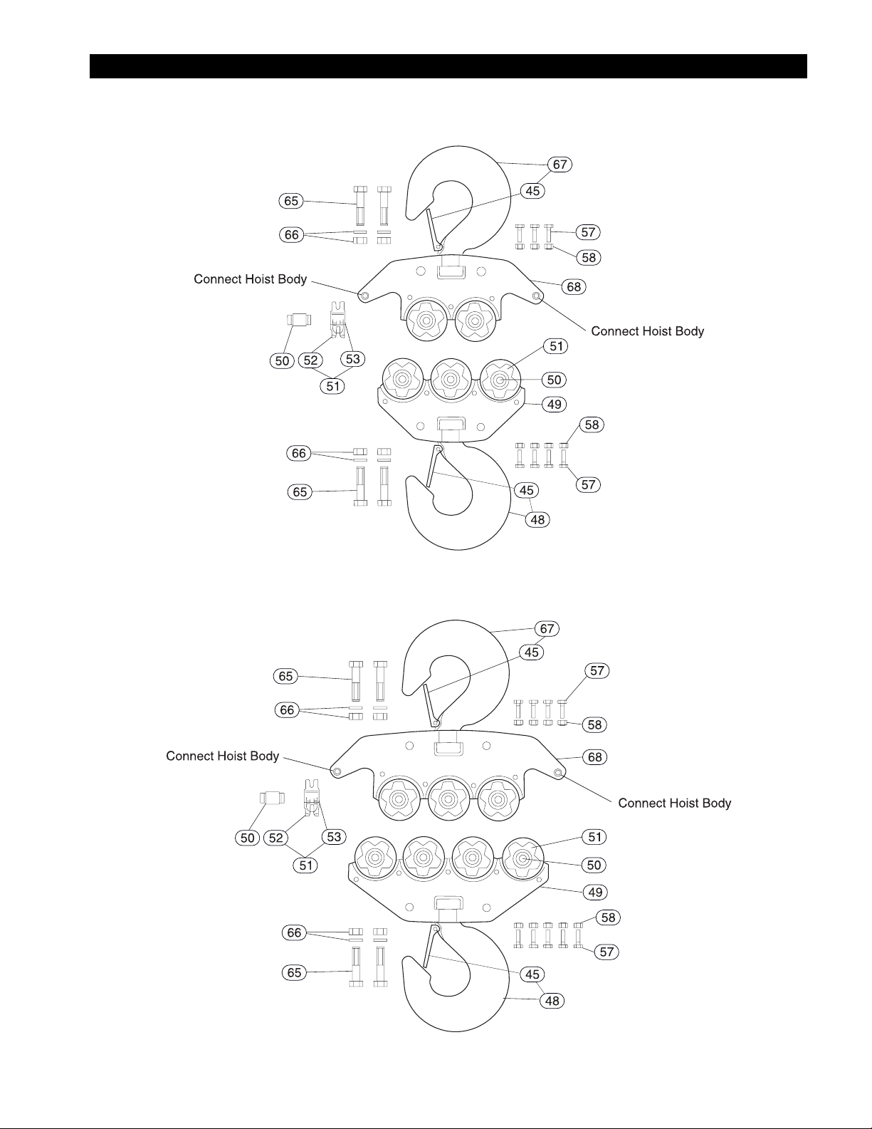
15 AND 20 TON TOP AND BOTTOM HOOK ASSEMBLY DRAWING
15 ton VL2
Top and Bottom Hook
(Dwg. MHP0046)
20 ton VL2
Top and Bottom Hook
(Dwg. MHP0047)
MHD56012 - Edition 8 13
Page 14

HOIST ASSEMBLY PARTS DRAWING
Connect
Load Chain
(Dwg. MHP0045)
14 MHD56012 - Edition 8
Page 15

HOIST ASSEMBLY PARTS LIST
ITEM
• 27
• 28
• 36
DESCRIPTION
NO.
OF PART
Side Plate 1 Assembly
1
(Incl’s item 5)
5 Needle Bearing w/Retainer Ring 2(4) 2372782 2372824 2372869 2372824 2372903
6 Load Sheave 1(2) 2372784 2372826 2372852 2372871 2372852 2372905
7 Load Chain Guide 2(4) 2372785 2372827 2372872 2372827 2372872
8 Chain Stripper 1(2) 2372786 2372828 2372873 2372828 2372873
9 Side Plate 2 Assembly 1(2) 2372787 2372829 2372853 2372874 2372853 2372906
10 Gear Bushing 4(8) 2372788 2372875 2372788 2372875
11 1st Gear 1(2) 2372789 2372830 2372854 2372876 2372854 2372907
12 Pinion Washer 1(2) 2372790 —
13 Pinion Shaft 1(2) 2372791 2372831 2372877 2372831 2372877
2nd Gear Set (Plain/Plain)
14
2nd Gear Set (Plain/Circle) — 71490296 — 71490296 71490312
15 3rd Gear 2(4) 2372793 2372833 2372879 2372833 2372909
16 Support Plate 1(2) 2372794 2372834 2372856 2372880 2372856 2372910
17 Gear Cover 1(2) 2372795 2372835 2372857 2372881 2372857 2372911
18 Hook Pin 1(2) 2372796 2372836 2372882 2372836 2372912
19 End Spring 1(2) 2372797
20 End Pin 1(2) 2372798 2372837 2372883 2372837 2372883
21 End Anchor A 1(2) 2372799 2372838 2372884 2372838 2372884
22 End Anchor B 1(2) 2372800 2372839 2372885 2372839 2372885
23 Spring 1(2) 2372801 2372840 2372858 2372886 2372858 2372913
24 Pawl 1(2) 2372802 2372887 2372802 2372887
25 Snap Link 1(2) 2372803 2372888 2372803 2372888
26 Hub 1(2) 2372804 2372841 2372889 2372841 2372889
Brake Disc 1 set 71112353 71112361 71112353 71112361
29 Ratchet Gear 1(2) 2372807 2372891 2372807 2372891
30 Brake Cover 1(2) 2372808 2372842 2372859 2372892 2372859 2372914
Handwheel 1(2) 2372809 2372843 2372860 2372893 2372860 2372915
Handwheel, Copper Plated* 1(2) 2372809-CP 2372843-CP 2372860-CP 2372893-CP 2372860-CP 2372915-CP
Handwheel (Overload Clutch) 1(2)
Handwheel Assembly with
31
Overload Clutch* (Incl’s items 31
thru 34 and 78 thru 82)
Handwheel Assembly with
Overload Clutch, Copper Plated *
(Incl’s items 31 thru 34 and 78 thru
82)
32 Washer 1(2) 2372810
33 Pinion Nut 1(2) 2372811
34 Cotter Pin 1(2) 2372812
Hand Chain Guide (2 piece) 2(4) 71026546 71026553 71026561 71026553 71026579
35
Hand Chain Guide (1 piece) 1(2) 12901 9967 12901 9967
Nylon Ring 2(4) 71026595
Bushing* 2(4) 2982-1
37 Snap Ring 2(4) 51398
Wheel Cover
38
Wheel Cover * 12545-4 12545-3 12545-2 12545-1 12545
40 U-Nut 6(12) 2372814 2372895 2372814 2372895
QTY.
TOTAL
1(2) 71029169 71029201 71029177 71029185 71029177 71029193
1(2)
Set(s)
1(2)
1(2)
1(2)
1/2 ton 1 ton 1-1/2 ton 2 ton 3 ton
71490270 71490288 — 71490304 —
71028955 71028963 71028971 71028989 71028971 71028997
PART NO.
Refer to page 19
5, 8, 10, 15
& 20 ton
MHD56012 - Edition 8 15
Page 16

HOIST ASSEMBLY PARTS LIST (CONTINUED)
ITEM
• 41
• 42
• 43
• 44
• 45
DESCRIPTION
NO.
OF PART
Top Hook Set (Incl’s Item 45 and
items 43 and 44 on 3 ton hoists)
Top Hook Set, Copper Plated
(Copper Plated Hook and Hook
Frames)*
Top Hook Set, Solid Bronze (Solid
Bronze Hook and Copper Plated
Hook Frames)*
Bottom Hook Set
(Incl’s item 45)
Bottom Hook Set, Copper Plated
(Copper Plated Hook and Hook
Frames) *
Bottom Hook Set, Solid Bronze
(Solid Bronze Hook and Copper
Plated Hook Frames)*
Chain Bolt
U-Nut
Hook Latch for Regular and
Copper Plated Hook
Hook Latch (Solid Bronze Hook) 51502 52377 52377 51202
Hand Chain
46
Hand Chain, Zinc Plated* HCCB005ZP HCCV020ZP HCCB005ZP HCCV020ZP
Load Chain
47
Load Chain, Nickel Plated* LCCF005ND LCCF010ND LCCF015ND LCCF020ND LCCF015ND LCCF025ND
Yoke Bolt (Copper Plated and solid
57
bronze only)
Yoke Nut (Copper Plated and solid
58
bronze only)
70 Model Label 1 Order Label Kit item 92
71 Warning Tag 1(2) Order Label Kit item 92
72 Tag Ring 1(2) 50040
73 Chain Installation Label 1(2) Order Label Kit item 92
74 Rivet 4 Use standard pop rivet
75 Bolt* 1 71031314
76 Washer* 1 12632
77 Nut* 1 71061584
78 Capacity Label 1 Order Label Kit item 92
Label Kit (Incl’s items 70, 71, 72
92
and 73)
QTY.
TOTAL
1
1
1 (2)
1 (2)
1
As Req’d
As Req’d
1 71069033 54560 71069033
1
1 71112437 71112445 71112452 71112460 71112478
1/2 ton 1 ton 1-1/2 ton 2 ton 3 ton
2372815 2372845 2372862 2372896 2372922
2372815-CP 2372845-CP 2372862-CP 2372896-CP 2372922-CP
2372815-SB 2372845-SB 2372862-SB 2372896-SB 2372922-SB
2372817 2372847 2372864 2372898 2372924
2372817-CP 2372847-CP 2372864-CP 2372898-CP 2372924-CP
2372817-SB 2372847-SB 2372864-SB 2372898-SB 2372924-SB
Order Kit
71490684
2372850 2372865 2372901 2372925
LCCF005 LCCF010 LCCF015 LCCV020 LCCF015 LCCF025
Order Kit
71490692
HCCB005 HCCV020 HCCB005 HCCV020
50852
PAR T NO.
71490700
Order Kit
5, 8, 10, 15
& 20 ton
Refer to
Parts List
Continuation
Order Kit
71492201
Refer to Parts List Continuation
Refer to
Parts List
Continuation
Refer to
Parts List
Continuation
* S•COR•E (Spark and Corrosion Resistant) feature.
( ) Items 43 and 44 quantities in parenthesis are for 3 and 5 ton hoist, other quantities in parentheses are for 15 and 20 ton hoists, which use
two manual chain hoist bodies.
• Recommended spare.
16 MHD56012 - Edition 8
Page 17

HOIST ASSEMBLY PARTS LIST (CONTINUED)
ITEM
• 41
• 42
• 43
• 44
• 45
DESCRIPTION
NO.
OF PART
Top Hook Set (Incl’s items 50, 51,
57, 58 and 65 thru 69)
Top Hook Set, Copper Plated
(Copper Plated Hook)*
Top Hook Set, Solid Bronze (Solid
Bronze Hook)*
Bottom Hook Set (Incl’s items 48,
49, 50, 51, 57, 58, 59, 61 thru 67)
Bottom Hook Set, Copper Plated
(Copper Plated Hook)*
Bottom Hook Set, Solid Bronze
(Solid Bronze Hook)*
Chain Bolt
U-Nut
Hook Latch Kit for Regular and
Copper Plated Hook
Hook Latch Kit (Solid Bronze Hook) 50597 50779 —
48 Bottom Hook Only 1 2372928 2372944 2372960 2372972 71108815 71108823
Bottom Frame
49
Bottom Frame, Copper Plated* 2372930-CP 2372946-CP 2372962-CP 2372974-CP —
50 Axle See ( ) 2372931 (1) 2372947 (1) 2372947 (2) 2372947 (3) 2372947 (5) 2372947 (7)
Idler Sheave with Needle Bearing
51
(Incl’s items 52 and 53)
52 Idler Sheave (no Bearing) See ( ) Order item 51
53 Needle Bearing for Axle See ( ) 2372933 (1) 2372949 (1) 2372949 (2) 2372949 (3) 2372949 (5) 2372949 (7)
Yoke Bolt See ( ) 2372783 (2) 2372825 (3) 2372870 (5) 2372904 (6) 71029136 (7) 71029136 (9)
57
Additional Yoke Bolt (Copper Plated
and Solid Bronze only)*
Yoke Nut See ( ) 2372816 (2) 2372846 (3) 2372863 (5) 2372897 (6) 2372897 (7) 2372897 (9)
58
Additional Yoke Nut (Copper Plated
and Solid Bronze only)*
59 Nut 1 2372918 —
60 Axle Washer 2 2373137 —
61 Thrust Bearing 1 2372934 2372950 2372963 2372975 —
62 Thrust Washer 1 2372935 2372951 2372964 2372976 —
63 C-Link 2 2372936 2372952 2372965 2372977 —
64 O-Link 1 2372937 2372953 —
65 Bolt B (for Clevis) 4 — 71029102
66 Nut and Washer (for item 65) 4 — 71029144
67 Top Hook 1 — 2372958 2372970 71108815 71108823
Top Hook Frame A
68
Top Hook Frame A, Copper Plated* 2372959-CP 2372971-CP —
Top Hook Frame B
69
Top Hook Frame B, Copper Plated* 2372980-CP 2372981-CP —
70 Model Label 1(2)
71 Warning Tag 1
74 Rivet 4(8) Use standard pop rivet
78 Capacity Label 1 Order Label Kit item 92
92 Label Kit (incl’s items 70 thru 73) 1 71112486 71112494 71112502 71112510 71112528
QTY.
TOTAL
1
1
1 (2)
1 (2) —
2
2
See ( ) 2372932 (1) 2372948 (1) 2372948 (2) 2372948 (3) 2372948 (5) 2372948 (7)
2 54558 54561 —
2 54559 54562 —
1
1
3 ton 5 ton 8 ton 10 ton 15 ton 20 ton
2372938 2372954 2372966 71037089 71037097
2372938-CP 2372954-CP 2372966-CP 71037089-CP 71037097-CP
2372938-SB 2372954-SB 2372966-SB 71037089-SB 71037097-SB
2372940 2372956 2372968 71037105 71037113
Refer to
Previous
Parts List
2372930 2372946 2372962 2372974 71029078 71029086
Not Sold Separately
Refer to
Previous
Parts List
2372940-CP 2372956-CP 2372968-CP 71037105-CP 71037113-CP
2372940-SB 2372956-SB 2372968-SB 71037105-SB 71037113-SB
2372941 2372957 2372969 71029045
PART NO.
Order Kit
71490718
2372959 2372971 71029227 71029129
2372980 2372981 71029227 71029129
Order Label Kit item 92
—
* S•COR•E (Spark and Corrosion Resistant) feature.
( ) Items 43 and 44 quantities in parenthesis are for 3 and 5 ton hoist, other quantities in parentheses are for 15 and 20 ton hoists, which
use two manual chain hoist bodies.
• Recommended spare.
MHD56012 - Edition 8 17
Page 18

HOIST OVERLOAD CLUTCH ASSEMBLY DRAWING AND PARTS LIST
(Dwg. MHP0322)
Refer to Hoist Assembly Parts List on pages 15 and 16 for items shown on drawing.
ITEM
DESCRIPTION
NO.
OF PART
Handwheel Assembly with Overload
Clutch (Incl’s items 31 thru 34, 78 thru 82,
93 and 94)
Handwheel Assembly with Overload
31
Clutch, Copper Plated* (Incl’s items 31
thru 34, 78 thru 82, 93 and 94)
Handwheel (Overload Clutch) 1(2) 71486872 71486880 71486898 71486906 71486898 71486914
Handwheel, Copper Plated* 1(2) 71486872-CP 71486880-CP 71486898-CP 71486906-CP 71486898-CP 71486914-CP
78 Supporter 1
79 Cone Wheel 1
80 Cone Spring 1
81 Washer 1
82 Nut 1
93 Ball** 1
94 Spring** 1
QTY.
TOTAL
1(2) 71487052 71487060 71487078 71487086 71487078 71487094
1(2) 71487052-CP 71487060-CP 71487078-CP 71487086-CP 71487078-CP 71487094-CP
1/2 ton 1 ton 1-1/2 ton 2 ton 3 ton
PART NUMBER
Not Sold Separately
Order Item 31
* S•COR•E (Spark and Corrosion Resistant) feature.
** Refer to page 21 for VL2 Hoist Revisions.
( ) Quantities in parentheses are for 15 and 20 ton hoist, which use two manual chain hoist bodies.
5, 8, 10, 15 &
20 ton
18 MHD56012 - Edition 8
Page 19

CHAIN CONTAINER ASSEMBLY (OPTIONAL)
(Dwg. MHP0321)
PART NU M B ER
ITEM
DESCRIPTION
NO.
OF PART
— Bracket Kit 1 22863* 1 22864**
86 Capscrew 2 53972 2 53972
87 Nut 2 54171 2 54171
88 Bracket 1 12064-2 1 12064-2
89 Capscrew 2 71125413 1 71125413
90 Washer 5 53978 3 53978
91 Chain Container 1 Refer to Chain Container Chart 1 Refer to Chain Container Chart
93 Strap 1 22862 1 22865
94 S-Hook —- —- 2 52120
QTY.
TOTAL
Low Capacity Chain Containers
All Hoist Capacities
QTY.
TOTAL
High Capacity Chain Containers
CC-6, CC-8 and CC-9
* Includes items 86 through 90 and 93.
** Includes items 86 through 90, 93 and 94.
MHD56012 - Edition 8 19
Page 20

Old Style
Parts for this style chain container assembly may be obsolete or out of production and may not be available.
ITEM
DESCRIPTION
NO.
OF PART
Bracket Kit
—
(Incl’s items 83 and 86 through 90)
83 Bracket 1 8725-3
84 Bracket 1 8725-2
85 Chain As Req’d HCCB005
86 Capscrew 2 52303
87 Nut 3 51682
88 Bracket 1 12064-1 12064-2 12064-1 12064-2
89 Capscrew 1 53546
90 Washer 1 53978
91 Chain Container 1 Refer to Chain Container Chart
QTY.
TOTAL
1 12586-1 12586-2 12586-3 12586-4
1/2 ton 1 ton 1-1/2 ton 2 ton 3 ton 5 ton
PART NUMBER
Chain Container Chart
Chain Container Part Number and Chain Length Capacity
Model
Number
VL2-005 20
VL2-010 13
VL2-015 10
VL2-020 —
VL2-030 —
VL2-050 —
VL2-080 —
VL2-100 —
71128029 71128037 71128052 71128045 71128060 71128078 CC-8 CC-6 CC-9
mft.m ft. mft.mft.m ft. mft.mft.m ft. m
ft.
64112.5 53 16 77 23.5 101 30.8 167 51 214 65.2 250 76.2 428 130.5
42683410.4 49 15 64 19.5 105 32 111 33.8 158 48 261 79.6
32062683811.6 50 15.2 82 25 95 29 124 37.8 202 61.6
—16 5216.4 30 94012.2 66 20 78 23.8 98 29.8 165 50.3
—10 3134195.8 25 7.6 41 12.5 47 14.3 62 19 101 30.8
—————123.7 15 4.6 25 7.6 29 8.8 38 11.6 62 19
———————10 3175.2 19 5.8 25 7.6 41 12.5
—————————123.7 14 4.3 19 5.8 31 9.4
Low Capacity High Capacity
8, 10, 15
& 20 ton
ACCESSORIES
Chain Lubricant LUBRI-LINK-GREEN
Overload Clutch Adjusting Socket 71112064
VL2 HOIST REVISIONS
VL2 Hoists manufactured prior to 1990 were supplied with a clip which was installed on wheel cover (38) and was held in position by nut
(40). The clip is not required and is no longer offered as a replacement part. Lack of this part will not affect hoist performance.
Overload clutches were supplied as an optional feature (not standard) on older versions of the VL2 hoist. Older hoists that were equipped
with an overload clutch did not use overload clutch ball (93) and spring (94). Supporter (78) and handwheel (31) are completely
interchangeable, between older and newer hoists.
20 MHD56012 - Edition 8
Page 21

CHAINING INFORMATION
1/2, 1, 1-1/2 and 2 ton Hoists
Single chain fall
(Dwg. MHP0037)
Note:
The 20 ton hoist is similar to the 15 ton hoist but uses one extra idle sheave on the top and bottom hook frames and has eight chain falls.
3 and 5 ton Hoists
Two chain falls
(Dwg. MHP0038)
8 ton Hoist
Three chain falls
(Dwg. MHP0443) (Dwg. MHP0444)
10 ton Hoist
Four chain falls
15 ton Hoist
Six chain falls
(Dwg. MHP0039)
PARTS ORDERING INFORMATION
Use of other than genuine Ingersoll-Rand replacement parts may
result in decreased hoist performance and may invalidate the
warranty. For prompt service and genuine Ingersoll-Rand parts
provide your nearest Distributor with the following:
1. Complete model number as it appears on the nameplate:
VL2 plus capacity (VL2-XXX).
2. Part number and part name as shown in manual.
3. Quantity required.
The hoist nameplate is located on the gear cover. Example shown
is for a 3 ton VL2 hoist.
For your convenience and future reference it is recommended that
the following information be recorded.
Hoist Model Number: __________________________________
Return Goods Policy
Ingersoll-Rand will not accept any returned goods for warranty
or service work unless prior arrangements have been made and
written authorization has been provided from the location where
the goods were purchased. Hoists returned with opened, bent or
twisted hooks, or without chain and hooks, will not be repaired or
replaced under warranty.
• Continuing improvement and advancement of design may
cause changes to this hoist which are not included in this
manual. Manuals are periodically revised to incorporate
changes. Always check manual edition number on front cover
for latest issue.
• If your hoist has special finish requirements for painted
parts, please specify when ordering.
Disposal
When the life of the hoist has expired, it is recommended that
hoist be disassembled, degreased and parts separated as to
materials so that they may be recycled.
Hoist Serial Number: __________________________________
Date Purchased: ______________________________________
MHD56012 - Edition 8 21
Page 22

SERVICE NOTES
22 MHD56012 - Edition 8
Page 23

WARRANTY
Ingersoll-Rand Company (I-R) warrants to the original user its
Hoists and Winches (Products) to be free of defects in material
and workmanship for a period of one year from the date of
purchase. I-R will repair, without cost, any Product found to be
defective, including parts and labor charges, or at its option, will
replace such Products or refund the purchase price less a
reasonable allowance for depreciation, in exchange for the
Product. Repairs or replacements are warranted for the remainder
of the original warranty period.
If any Product proves defective within its original one year
warranty period, it should be returned to any Authorized Hoist and
Winch Service Distributor, transportation prepaid with proof of
purchase or warranty card.
This warranty does not apply to Products which I-R has
determined to have been misused or abused, improperly
maintained by the user, or where the malfunction or defect can be
attributed to the use of non-genuine I-R parts.
IMPORTANT NOTICE
It is our policy to promote safe delivery of all orders.
This shipment has been thoroughly checked, packed and inspected
before leaving our plant and receipt for it in good condition has
been received from the carrier. Any loss or damage which occurs
to this shipment while enroute is not due to any action or conduct
of the manufacturer.
Visible Loss or Damage
If any of the goods called for on the bill of lading or express
receipt are damaged or the quantity is short, do not accept them
until the freight or express agent makes an appropriate notation on
your freight bill or express receipt.
I-R makes no other warranty, and all implied warranties
including any warranty of merchantability or fitness for a
particular purpose are limited to the duration of the expressed
warranty period as set forth above. I-R’s maximum liability is
limited to the purchase price of the Product and in no event
shall I-R be liable for any consequential, indirect, incidental,
or special damages of any nature rising from the sale or use of
the Product, whether based on contract, tort, or otherwise.
Note: Some states do not allow limitations on incidental or
consequential damages or how long an implied warranty lasts so
that the above limitations may not apply to you.
This warranty gives you specific legal rights and you may also
have other rights which may vary from state to state.
Damage Claims
You must file claims for damage with the carrier. It is the
transportation company’s responsibility to reimburse you for
repair or replacement of goods damaged in shipment. Claims for
loss or damage in shipment must not be deducted from the
Ingersoll-Rand invoice, nor should payment of Ingersoll-Rand
invoice be withheld awaiting adjustment of such claims as the
carrier guarantees safe delivery.
You may return products damaged in shipment to us for repair,
which services will be for your account and form your basis for
claim against the carrier.
Concealed Loss or Damage
When a shipment has been delivered to you in apparent good
condition, but upon opening the crate or container, loss or damage
has taken place while in transit, notify the carrier’s agent
immediately.
MHD56012 - Edition 8 23
Page 24

 Loading...