

Ingersoll-Rand UP6 20 HP, UP6 15HP, UP6 25 HP, UP6 30 HP Option Manual
UP6 15, UP6 20, UP6 25, UP6 30
OPTIONS MANUAL
Intellisys Option
Dryer Option
High Dust Option
Outdoor Module Option
PORO Option
60Hz
This manual contains
important safety information
and must be made available
to personnel who operate and
maintain this machine.
C.C.N. : 80445174
REV : B
DATE : JANUARY 2009


CONTENTS & ABBREVIATIONS
http:/air.ingersollrand.com
UP6 15, UP6 20, UP6 25, UP6 30
1
CONTENTS
1 CONTENTS
2 FOREWORD
3 DECALS
6 SAFETY
8 INTELLISYS OPTION
31 DRYER OPTION
47 HIGH DUST FILTER OPTION
48 OUT DOOR MODULE OPTION
49 PORO OPTION – ELECTRO–PNEUMATIC
53 PORO OPTION – INTELLISYS
ABBREVIATIONS & SYMBOLS
#### Contact Ingersoll Rand for serial number
–>#### Up to Serial No.
####–> From Serial No.
* Not illustrated
{ Option
NR Not required
AR As required
SM Sitemaster/Sitepack
HA High ambient machine
WC Watercooled machine
AC Aircooled machine
ERS Energy recovery system
T.E.F.C. Totally enclosed fan cooled motor (IP55)
O.D.P. Open drip proof (motor)
2
UP6 15, UP6 20, UP6 25, UP6 30
http:/air.ingersollrand.com
FOREWORD
This manual is provided to cover instructions and technical data
for additional options to the standard UP compressor range. It is
provided as a SUPPLEMENT to the standard operators and parts
manuals and should NOT be used for the operation of the
complete machine.
The contents of this manual are considered to be proprietary and
confidential to Ingersoll Rand and should not be reproduced without
the prior written permission of Ingersoll Rand.
Nothing contained in this document is intended to extend any
promise, warranty or representation, expressed or implied, regarding
the Ingersoll Rand products described herein. Any such warranties or
other terms and conditions of sale of products shall be in accordance
with the standard terms and conditions of sale for such products, which
are available upon request.
This manual contains instructions and technical data to cover
routine operation and scheduled maintenance tasks by operation and
maintenance staff. Major overhauls are outside the scope of this
manual and should be referred to an authorized Ingersoll Rand service
department.
All components, accessories, pipes and connectors added to the
compressed air system should be:
. of good quality, procured from a reputable manufacturer and,
wherever possible, be of a type approved by Ingersoll Rand.
. clearly rated for a pressure at least equal to the machine maximum
allowable working pressure.
. compatible with the compressor lubricant/coolant.
. accompanied with instructions for safe installation, operation and
maintenance.
Details of approved equipment are available from Ingersoll Rand
Service departments.
The use of non–genuine spare repair parts other than those
included within the Ingersoll Rand approved parts list may create
hazardous conditions over which Ingersoll Rand has no control.
Therefore Ingersoll Rand does not accept any liability for losses
caused by equipment in which non–approved repair parts are installed.
Standard warranty conditions may be affected.
The intended uses of this machine are outlined below and examples
of unapproved usage are also given, however Ingersoll Rand cannot
anticipate every application or work situation that may arise.
IF IN DOUBT CONSULT SUPERVISION.
This machine has been designed and supplied for use only in the
following specified conditions and applications:
. Compression of normal ambient air containing no known or
detectable additional gases, vapors, or particles
. Operation within the ambient temperature range specified in the
GENERAL INFORMATION section of this manual.
The use of the machine in any of the situation types listed in
table 1:–
a) Is not approved by Ingersoll Rand,
b) May impair the safety of users and other persons, and
c) May prejudice any claims made against Ingersoll Rand.
TABLE 1
Use of the machine to produce compressed air for:
a) direct human consumption
b) indirect human consumption, without suitable filtration and purity
checks.
Use of the machine outside the ambient temperature range
specified in the GENERAL INFORMATION SECTION of this manual.
Use of the machine where there is any actual or foreseeable risk of
hazardous levels of flammable gases or vapors.
THIS MACHINE IS NOT INTENDED AND MUST NOT BE
USED IN POTENTIALLY EXPLOSIVE ATMOSPHERES,
INCLUDING SITUATIONS WHERE FLAMMABLE GASES OR
VAPOURS MAY BE PRESENT.
Use of the machine fitted with non Ingersoll Rand approved
components.
Use of the machine with safety or control components missing or
disabled.
The company accepts no responsibility for errors in translation of
this manual from the original English version.
Ingersoll Rand reserves the right to make changes and
improvements to products without notice and without incurring any
obligation to make such changes or add such improvements to
products sold previously.
INTELLISYS is a registered trademark of Ingersoll Rand
Company USA.
¤ COPYRIGHT 2008
INGERSOLL RAND
DECALS 3
http:/air.ingersollrand.com
UP6 15, UP6 20, UP6 25, UP6 30
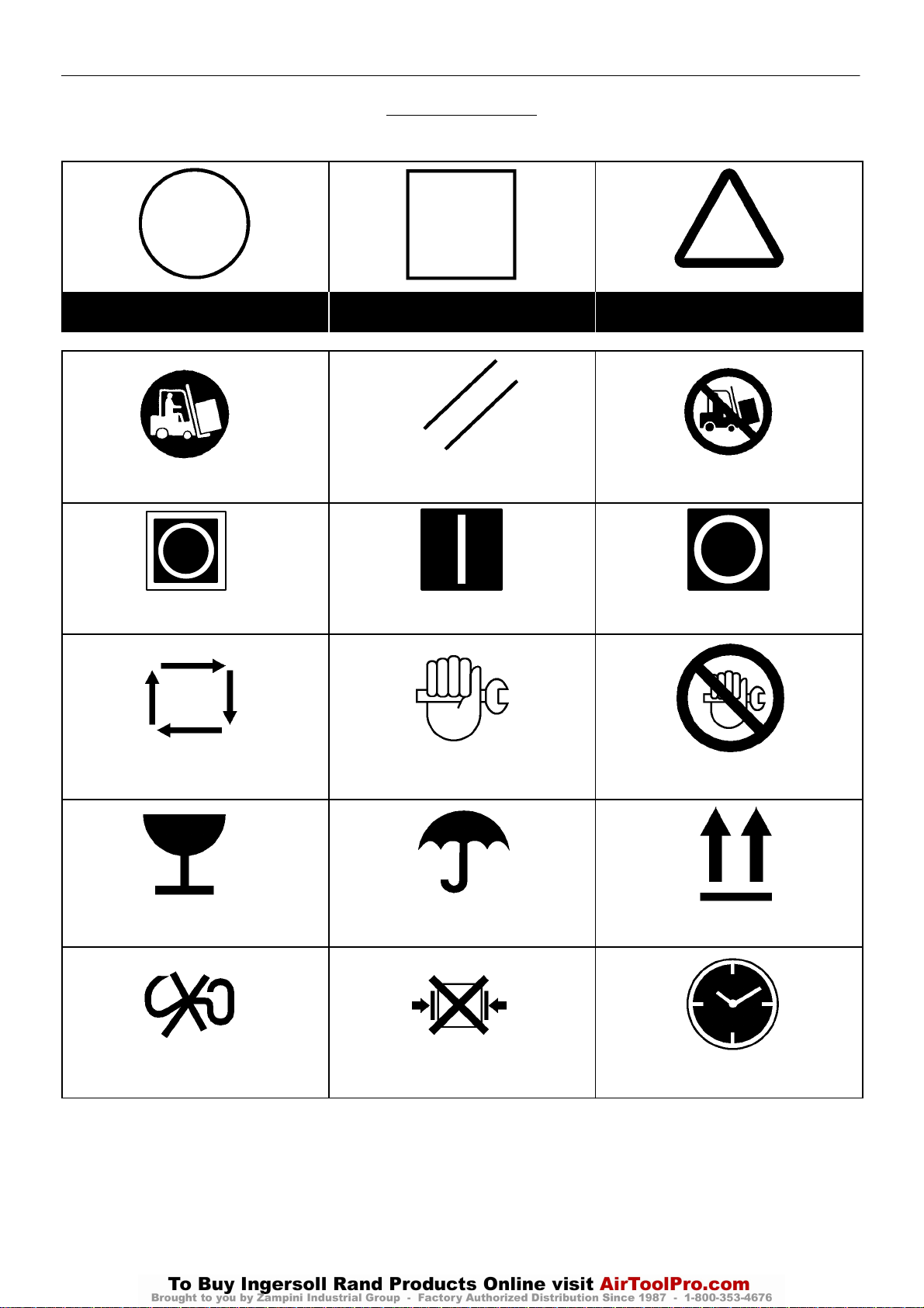
ISO SYMBOLS
GRAPHIC FORM AND MEANING OF ISO SYMBOLS
Prohibition / Mandatory Information / Instructions Warning
Use fork lift truck from this side only. RESET Do not use fork lift truck from this side.
Emergency stop. On (power). Off (power).
AUTOMATIC RESTART MAINTENANCE MAINTENANCE PROHIBITED
FRAGILE KEEP DRY THIS WAY UP
USE NO HOOKS NO SIDE CLAMPS HOURS
DECALS4
UP6 15, UP6 20, UP6 25, UP6 30
http:/air.ingersollrand.com
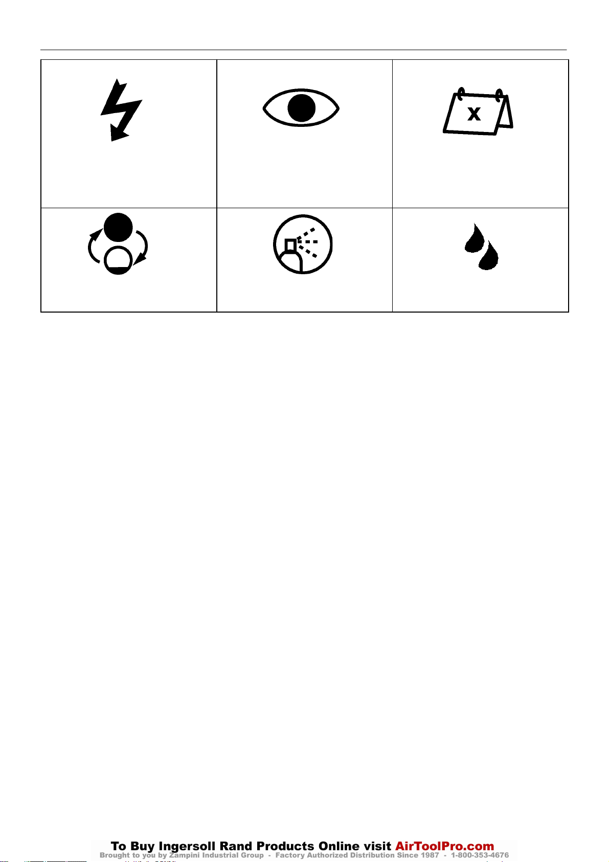
POWER INSPECT
CHANGE / REPLACE CLEAN
Every X months, if sooner than required by
operating hours
MOISTURE
DECALS 5
http:/air.ingersollrand.com
UP6 15, UP6 20, UP6 25, UP6 30
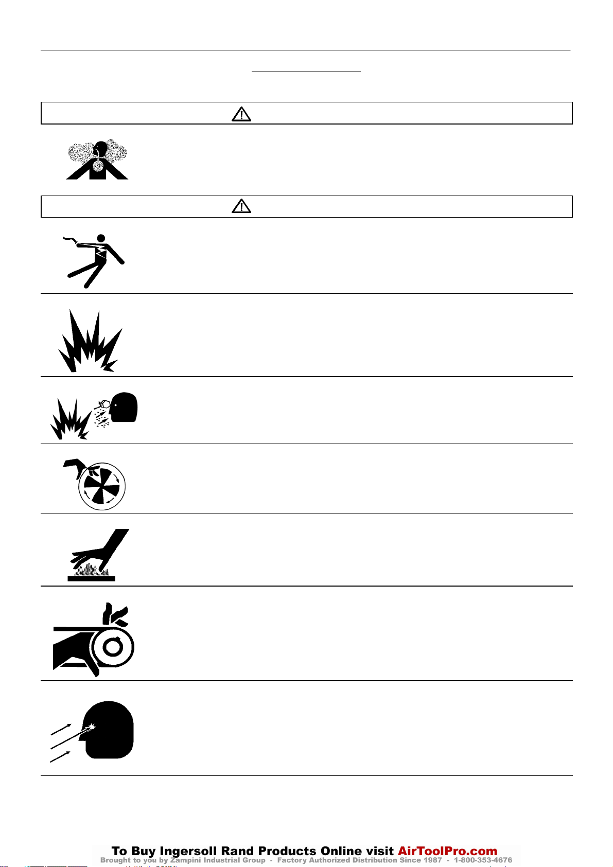
ANSI SYMBOLS
GRAPHIC FORM AND MEANING OF ANSI SYMBOLS
DANGER
INTAKE AIR. Can contain carbon monoxide or other contaminants. Will cause serious injury or death. Ingersoll Rand
air compressors are not designed, intended or approved for breathing air. Compressed air should not be used for
breathing air applications unless treated in accordance with all applicable codes and regulations.
WARNING
HAZARDOUS VOLTAGE. Can cause serious injury or death. Disconnect power and bleed pressure from tank before
servicing. Lockout/Tagout machine. Compressor must be connected to properly grounded circuit. See Grounding
Instructions in manual. Do not operate compressor in wet conditions. Store indoors.
RISK OF FIRE OR EXPLOSION. Electrical arcing from compressor components can ignite flammable liquids and
vapors which can result in serious injury. Never operate the compressor near flammable liquids or vapors. If used to
spray flammable materials, keep compressor at least 20ft away from the spray area.
HIGH PRESSURE AIR. Rusted tanks can cause explosion and severe injury or death. Receiver under pressure.
Operator should relieve tank pressure before performing maintenance. In addition to automatic drain, operate manual
drain valve weekly. Manual drain valve located at bottom of the tank.
MOVING PARTS. Can cause serious injury. Do not operate with guards removed. Machine may start automatically.
Disconnect power before servicing. Lockout/Tagout machine.
HOT SURFACES. Can cause serious injury. Do not touch. Allow to cool before servicing. Do not touch hot
compressor or tubing.
EXPOSED MOVING BELTS AND SHEAVES.
Can cause severe injury or death.
Do not operate without guard in place. Disconnect power before servicing.
Lockout/Tagout machine.
Air flow exhaust may contain flying debris.
Safety protection should be worn at all times.

6
UP6 15, UP6 20, UP6 25, UP6 30
http:/air.ingersollrand.com
SAFETY
DANGER!
Hazard that WILL cause DEATH, SEVERE INJURY or substantial
property damage if ignored. Instructions must be followed precisely to
avoid injury or death.
WARNING!
Hazard that CAN cause DEATH, SEVERE INJURY or substantial
property damage if ignored. Instructions which must be followed
precisely to avoid injury or death.
CAUTIONS!
Cautions call attention to instructions which must be followed
precisely to avoid damaging the product, process or its surroundings.
NOTES
Notes are used for supplementary information.
BREATHING AIR PRECAUTION
Ingersoll Rand air compressors are not designed, intended or
approved for breathing air. Compressed air should not be used for
breathing air applications unless treated in accordance with all
applicable codes and regulations.
General Information
Ensure that the operator reads and understands the decals and
consults the manuals before maintenance or operation.
Ensure that the Operation and Maintenance manual is not removed
permanently from the machine.
Ensure that maintenance personnel are adequately trained,
competent and have read the Maintenance Manuals.
Do not point air nozzles or sprayers toward anyone.
Compressed air and electricity can be dangerous. Before
undertaking any work on the compressor, ensure that the electrical
supply has been isolated and the compressor has been relieved of all
pressure.
Wear eye protection when operating or servicing compressor.
All persons positioned near to operating machinery should be
equipped with hearing protection and given instructions on its use in
accordance with workplace safety legislation.
Make sure that all protective covers are in place and that the
canopy/doors are closed during operation.
The specification of this machine is such that the machine is not
suitable for use in flammable gas risk areas.
Installation of this compressor must be in accordance with
recognized electrical codes and any local Health and Safety Codes.
The use of plastic bowls on line filters can be hazardous. Their
safety can be affected by either synthetic lubricants, or the additives
used in mineral oils. Ingersoll Rand recommends that only filters with
metal bowls should be used on a pressurized system.
Compressed air
Compressed air can be dangerous if incorrectly handled. Before
doing any work on the unit, ensure that all pressure is vented from the
system and that the machine cannot be started accidentally.
All air pressure equipment installed in or connected to the machine
must have safe working pressure ratings of at least the machine rated
pressure.
If more than one compressor is connected to one common
downstream plant, effective isolation valves must be fitted and
controlled by work procedures, so that one machine cannot accidently
be pressurized / over pressurized by another.
Compressed air must not be used for a direct feed to any form of
breathing apparatus or mask.
The discharged air contains a very small percentage of compressor
lubricant and care should be taken to ensure that downstream
equipment is compatible.
If the discharged air is to be ultimately released into a confined
space, adequate ventilation must be provided.
When using compressed air always use appropriate personal
protective equipment.
All pressure containing parts, especially flexible hoses and their
couplings, must be regularly inspected, be free from defects and be
replaced according to the Manual instructions.
Compressed air can be dangerous if incorrectly handled. Before
doing any work on the unit, ensure that all pressure is vented from the
system and that the machine cannot be started accidentally.
Avoid bodily contact with compressed air.
All safety valves located in the separator tank must be checked
periodically for correct operation.
Do not over–pressurize the receiver tank or similar vessels beyond
design limits.
Do not use a receiver tank or similar vessels that fail to meet the
design requirements of the compressor. Contact your distributor for
assistance.
Do not drill into, weld or otherwise alter the receiver tank or similar
vessels.
Materials
The following substances are used in the manufacture of this
machine and may be hazardous to health if used incorrectly:
. preservative grease
. rust preventative
. compressor coolant
AVOID INGESTION, SKIN CONTACT AND INHALATION OF
FUMES
Transport
When loading or transporting machines ensure that the specified
lifting and tie down points are used.
Lifting equipment must be properly rated for the weight of the
compressor.
Do not work on or walk under the compressor while it is suspended.
WARNING
Imposing a normal or emergency stop on the compressor will
only relieve presure upstream of the minimum pressure valve on
top of the separator tank.
If maintenance work is required downstream of this valve, ensure
that all pressure is relieved at the process vent point external to
the compressor
Ensure that the machine is operating at the rated pressure and that
the rated pressure is known to all relevant personnel.

Electrical
http:/air.ingersollrand.com
UP6 15, UP6 20, UP6 25, UP6 30
Keep all parts of the body and any hand–held tools or other
conductive objects, away from exposed live parts of the compressor
electrical system. Maintain dry footing, stand on insulating surfaces
and do not contact any other portion of the compressor when making
adjustments or repairs to exposed live parts of the compressor
electrical system.
WARNING
Any electrical connections or adjustments should only be
made by a suitably qualified electrician
Close and lock all access doors when the compressor is left
unattended.
Do not use extinguishers intended for Class A or Class B fires on
electrical fires. Use only extinguishers suitable for class BC or class
ABC fires.
Attempt repairs only in clean, dry, well lighted and ventilated areas.
Connect the compressor only to electrical systems that are
compatible with its electrical characteristics and that are within it’s rated
capacity.
Condensate disposal
As waste water regulations vary by country and region it is the
responsibility of the user to establish the limitations and regulations in
their particular area. Ingersoll Rand and its associated distributors are
happy to advise and assist in these matters.
For further information, consult Material Data
80440043 MSDS, Ultra Coolant English
80440068 MSDS, Ultra Coolant Spanish
80440050 MSDS, Ultra Coolant Portuguese
80442254 MSDS, Xtend Food Grade Coolant English
SAFETY
7
8
UP6 15, UP6 20, UP6 25, UP6 30
http:/air.ingersollrand.com
INTELLISYS CONTROL AND INSTRUMENTATION
INTELLISYS OPTION
PRIOR TO STARTING
1. Check coolant level. Add if necessary.
2. Make sure main discharge valve is open.
3. Turn on electrical isolator. The power L.E.D. will illuminate and the
display will indicate ‘Ready to start’.
WARNING
Make sure that all protective covers are in place.
STARTING
Press ‘Start’ [24]. The compressor will start and then load
automatically.
POWER OUT RESTART (Optional)
If this setting is set to ON, the compressor will automatically restart
when power is returned to the compressor if it was operating when
power was removed.
POWER OUT RESTART TIME
If the power out restart setting is set to ON, this is the number of
seconds from the time power is restored until the compressor starts.
The power out restart horn will sound during this time.
NORMAL STOPPING
1. Press ‘Unloaded Stop’[25]. The compressor will unload then stop.
2. Turn off electrical isolator.

INTELLISYS OPTION
http:/air.ingersollrand.com
UP6 15, UP6 20, UP6 25, UP6 30
9
EMERGENCY STOP
1. Press ‘Emergency stop button’ [26] and the compressor will stop
immediately.
2. Turn off electrical isolator.
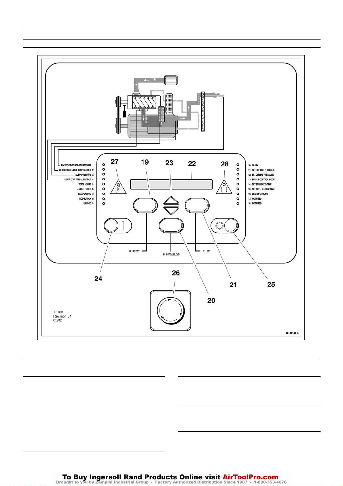
INSTRUMENT PANEL FUNCTION
1 PACKAGE DISCHARGE PRESSURE L.E.D.
This will illuminate when the display indicates the package
discharge pressure.
2 AIREND DISCHARGE TEMPERATURE L.E.D.
This will illuminate when the display indicates the airend discharge
temperature.
3 SUMP PRESSURE L.E.D.
This will illuminate when the display indicates the sump pressure.
4 SEPARATOR PRESSURE DROP L.E.D.
This will illuminate when the display indicates the separator
pressure drop.
5 TOTAL HOURS L.E.D.
This will illuminate when the display indicates the total compressor
running hours.
6 LOADED HOURS L.E.D.
This will illuminate when the display indicates the total loaded
compressor hours.
7 LOAD/UNLOAD L.E.D.
This will illuminate when the compressor is running onload.
15 L.E.D.–Set auto restart time.
16 L.E.D.–Select options.
17 L.E.D.–Not used.
18 L.E.D.–Not used.
19 DISPLAY SELECT BUTTON
Press to index through compressor operating conditions. The
corresponding L.E.D. will illuminate adjacent to display.
This is used to select alternative status displays (after
approximately 5 minutes, the display defaults to the package discharge
pressure). Depressing this button in the set point routine will cause exit
to checking machine for 2 seconds, then ready to start.
20 LOAD/UNLOAD BUTTON
These are used to manually switch the compressor between a
loaded control mode (e.g. on/off line) and unloaded running.
See L.E.D.
21 SET BUTTON
Depressing this button when the compressor is stopped will enable
entry into the set point routine. When in the set point routine, depressing
this button will cause the controller to move on to the next set point
setting, saving the new value if one has been entered.
A warning reset is obtained by depressing this button (while the
machine is running). An alarm reset is obtained by depressing this
button twice within 3 seconds (the alarm condition will remain if the
indicated fault has not been rectified).
22 LIQUID CRYSTAL DISPLAY
This indicates the status of the compressor, set up parameters and
warning/alarm messages. When the compressor is running, the
display will normally show the package discharge pressure.
8 MODULATION L.E.D.
This will illuminate when the compressor is running in modulation
mode. (Note: capacity modulation will occur only if the appropriate
regulation pneumatics are fitted to the compressor).
9 UNLOAD L.E.D.
This will illuminate when the compressor is running in unload mode.
10 ALARM L.E.D.
This will flash when a warning condition exists. The warning
detected will be displayed and the compressor will continue to run. The
warning can be reset by depressing set [21].
It will illuminate when an alarm condition has occurred. The
compressor will shutdown immediately. The alarm can be reset by
depressing set [21] twice within 3 seconds.
OTHER L.E.D.s
These will illuminate during the set point routine to indicate which
function is being adjusted.
11 L.E.D.–Set off line pressure.
12 L.E.D.–Set on line pressure.
13 L.E.D.–Select control mode.
14 L.E.D.–Set star delta time.
23 ARROW KEYS
These are used to index through warning and alarm messages. In
the set point routine, these buttons are used to increase/decrease set
point values and enable/disable some operation conditions.
The arrow keys are also used to select pressure bands 1 (Y) or 2
(B) during normal operation of the compressor.
24 START BUTTON
This button when depressed will cause the compressor to start and
load automatically, provided that the controller detects a demand for air.
When pressed in the display mode, it will cause exit to checking
machine for 2 seconds, then ready to start.
25 UNLOADED STOP
This button when depressed while the compressor is running, will
unload the compressor (if not already unloaded) for 10 seconds and
then stop. This is the normal method for stopping the compressor. If the
compressor is already stopped, it will execute an L.E.D. check (all the
L.E.D.s should illuminate) and display the controller software revision.
26 EMERGENCY STOP
This button when depressed will stop the compressor immediately
and display an emergency stop alarm message.

10
UP6 15, UP6 20, UP6 25, UP6 30
http:/air.ingersollrand.com
INTELLISYS OPTION
27 POWER L.E.D.
This will illuminate when the 8V controller supply is available.
28 AUTOMATIC RESTART L.E.D.
This will illuminate when the machine has shutdown due to low air
demand. The compressor will restart and load automatically as soon
as the demand for air resumes.
DISPLAY MESSAGES
When the compressor is running normally, the display will indicate
the package discharge pressure and illuminate the corresponding
L.E.D. [1]. An arrow will also appear in the far right of the display
indicating pressure band selection. Pressing display select [19] will
change the display value and the corresponding L.E.D. will illuminate.
The controller monitors all aspects of the compressor while running and
will display warnings or in severe conditions execute an emergency
stop and display alarm conditions.
MACHINE CONTROL MODES
CAPACITY CONTROL
The compressor is designed to work with two types of capacity
control, to suit the individual plant requirements. These controls are:–
A. On line – Off line. (Fitted as standard)
B. On line – Off line, with Upper Range Modulation. (Optional extra)
Either is available by selection at the control panel.
ON LINE – OFF LINE CONTROL
For applications that require a widely varying air demand, this
mode of control will deliver air at full capacity or zero capacity with
low receiver pressure.
This mode of operation is controlled by the pressure transducer
responding to changes in plant air pressure. This sensorenergizes
the load solenoid valve which in turn operates the venting valve
(blowdown) and the closing of the atmospheric vent opening in the
air inlet valve.
The compressor then delivers full capacity air to the plant
system. If the air pressure in this system rises to the upper set point
of the pressure setting, the load solenoid valve is de–energized
allowing the inlet valve to close. At the same time, the venting valve
opens allowing the receiver pressure to drop.
The pressure setting has a range of 12 psi (0.83 bar) between
its upper and lower set points.The upper set point is set at 3 psi (0.2
bar) above the compressor rated discharge pressure.
UPPER RANGE MODULATION CONTROL (Optional Extra)
For plants having a relatively high and constant air demand,
Upper Range Modulation is the recommended mode of control.
Upper range modulation retains the features of On line – Off line
control but provides the throttling of the inlet air flow as the line
pressure rises to the upper set point of the off–line pressure setting.
AUTOMATIC START/STOP
For plants that have a widely varying plant air demand, larger air
storage capacity, and/or want automatically available stand–by air
capacity, Automatic Start–Stop Control Option is available.
During periods of low demand, if the line pressure rises to the off line
air pressure set point of the lntellisys® , a timer is energized and begins
to time out. The automatic restart time is adjustable in a 2–60 minute
range. The timer will continue to operate as long as the plant line
pressure remains above the on line set point of the Intellisys® . If the
timer continues to operate for as long as its adjusted time setting, a
contact in the lntellisys opens to de–energize the compressor starter
coils. At the same time, a yellow Automatic Restart light on the
lntellisys® panel is lit and the message AUTO RESTART will be
displayed to indicate the compressor has shut down automatically and
will restart automatically.
The automatic restart will take place when the line pressure drops
to the online set point of the Intellisys® .
To operate in the automatic start/stop mode, proceed with the
following steps:
1. Press the SET button until the message AUTO S/S OFF is
displayed.
2. Push the up or down arrows to select the auto start/stop function (on
or off). AUTO S/S OFF in the display indicates auto start/stop is
disabled (off). AUTO S/S ON in the display indicates auto start/stop is
enabled (on). Press the SET button to store function. The display will
flash to acknowledge and then display AUTO S/S 10 MIN.
3. Press the up or down arrows to select the desired automatic restart
time (2–60 min. range). The default value is 10 minutes. Press SET
button to store the value.The display will flash to acknowledge. Press
the DISPLAY SELECT button or wait 30 seconds for the controller to
automatically exit the set routine.The display returns to READY TO
START.
4. Start the compressor and adjust the isolation valve to allow the unit
to slowly reach the offline pressure and unload.The compressor should
run for a minimum of 10 min. and unloaded for the pre–set time and then
shut down.
5. The compressor should restart automatically when the system air
pressure drops below the online air pressure setting.
CONTROLLER WARNING MESSAGES
In the event of a warning, the controller will display a message and
thealarm L.E.D. [10] will flash. The warning message will alternate with
the normal display every 4 seconds, the compressor will continue to run
but the fault should be rectified as soon as possible. The arrow keys
[23] should be used to index the display for any additional warning
messages. A warning message may be reset by depressing set [21]
once.
NOTE:
The warning will recur if the fault has not been rectified. The
following warning messages may be displayed:
SEPARATOR ELEMENT
The separator element is dirty or blocked and should be replaced.
By bleeding off a small amount from the regulator valve, which
energises the Modulate Solenoid Valve, a reduction in the air signal
to the pneumatic cylinder on the inlet valve allows the cylinder to
‘trim’ the inlet valve position as dictated by changing line pressure.
Modulation begins when the compressor reaches about 94% of the
rated line pressure and is factory set to modulate down to
approximately70% of rated capacity.
If the air demand decreases to a level below the 70% modulated
output, the line pressure will increase slightly to the upper limit of the
pressure setting, when the compressor then changes to the Off line
control position and operates with the receiver vented.
AIREND TEMPERATURE
The airend temperature reaches 97% of the high airend
temperatureset point (i.e. 223 F (106 C)).

INTELLISYS OPTION
http:/air.ingersollrand.com
UP6 15, UP6 20, UP6 25, UP6 30
11
CONTROLLER ALARMS
In the event of an alarm, the controller will execute an emergency
stop, the alarm L.E.D. [10] will illuminate and an alarm message will be
displayed. The arrow keys [23] should be used to index the display for
any additional alarm messages. An alarm is reset by depressing set
[21] twice within a 3 second period after the fault has been rectified. The
compressor will restart only when all alarm conditions have been
rectified. The following alarm messages may be displayed (For fault
correction see the Fault Finding section):
STARTER FAULT
The contactor sequence during start or stop is incorrect.
AIREND TEMPERATURE
The airend discharge temperature is above the high temperature
set point.
MOTOR OVERLOAD
The motor overload contacts are open. The motor overload must be
reset before the controller can be reset.
REVERSE ROTATION
No sump pressure is detected after the first 2 seconds of running.
Isolate the machine and reverse the mains supply connections before
resuming.
OVER PRESSURE
The line pressure is 15 psi (1 bar) greater than the rated discharge
pressure.
TEMPERATURE SENSOR 1
The airend temperature sensor/ connecting cable has failed.
TEMPERATURE SENSOR 2
The separator tank temperature sensor/connecting cable has
failed.
PRESSURE SENSOR
Indicates pressure transducer failure / connecting cable fault.
FIELD OPTION/S
Before installation and operation of this option, these instructions
should be studied carefully to obtain a clear knowledge of the option
and its application to the compressor.
REMOTE START/STOP
The Remote Start/Stop Option allows the operator to control the
compressor from a remote mounted start/stop station.Terminal points
are provided in connector J1 in the top of the lntellisys controller; one
a connection for a normally closed stop switch (terminals 3 and 4), and
one for a normally open, momentary contact start switch (terminals 5
and 6). Refer to the compressor wiring schematic for specific
connection points.
For safety, a selection is available in the lntellisys set–points to
disable the remote start and stop function.This allows the compressor
to be fully controlled by the lntellisys and not from the remote
start/stop station.
If the remote start switch is momentarily closed, the lntellisys
starts the compressor.The remote stop switch is normally closed. If the
remote stop switch opens, the compressor will unload and stop.The
compressor cannot restart until the remote stop switch has been reset
to a closed position. (EMERGENCY STOP will display on the
lntellisys if the stop switch is not closed).
To operate in the remote start/stop mode, proceed with the
following steps:
1. Press the SET button until the message REMOTE S/S OFF is
displayed.
2. Push the up or down arrows to select the remote start/stop function
(on or off). REMOTE S/S OFF in the display indicates remote start/stop
is disabled (off). REMOTE S/S ON in the display indicates remote
start/stop in enabled (on). Press the SET button to store the function.
The display will flash to acknowledge. Press the DISPLAY SELECT
button or wait 30 seconds for the controller to automatically exit the set
routine.The display returns to READY TO START.
3. Start the compressor with the Start button on the Intellisys control
panel.The compressor must be started locally first before the Remote
Start/Stop buttons are activated by the lntellisys.
FAILED CALIBRATION
During calibration routine, a 10% of scale error has been detected.
Ensure that the separator is completely blowndown and repeat
calibration.
CONTROL POWER LOSS
The 48Vac signal is not present at the controller.
REMOTE START FAILURE
Momentary remote start has not disengaged before star–delta
transition. This alarm is active only if the remote start/stop is enabled.
REMOTE STOP FAILURE
The momentary remote stop switch has not disengaged when the
start signal is received. This alarm is active only if the remote start/stop
is enabled.
EMERGENCY STOP
The emergency stop button is engaged.
LOW SUMP PRESSURE
The sump pressure drops below 15 psi (1 bar) during normal
operation.
12
UP6 15, UP6 20, UP6 25, UP6 30
http:/air.ingersollrand.com
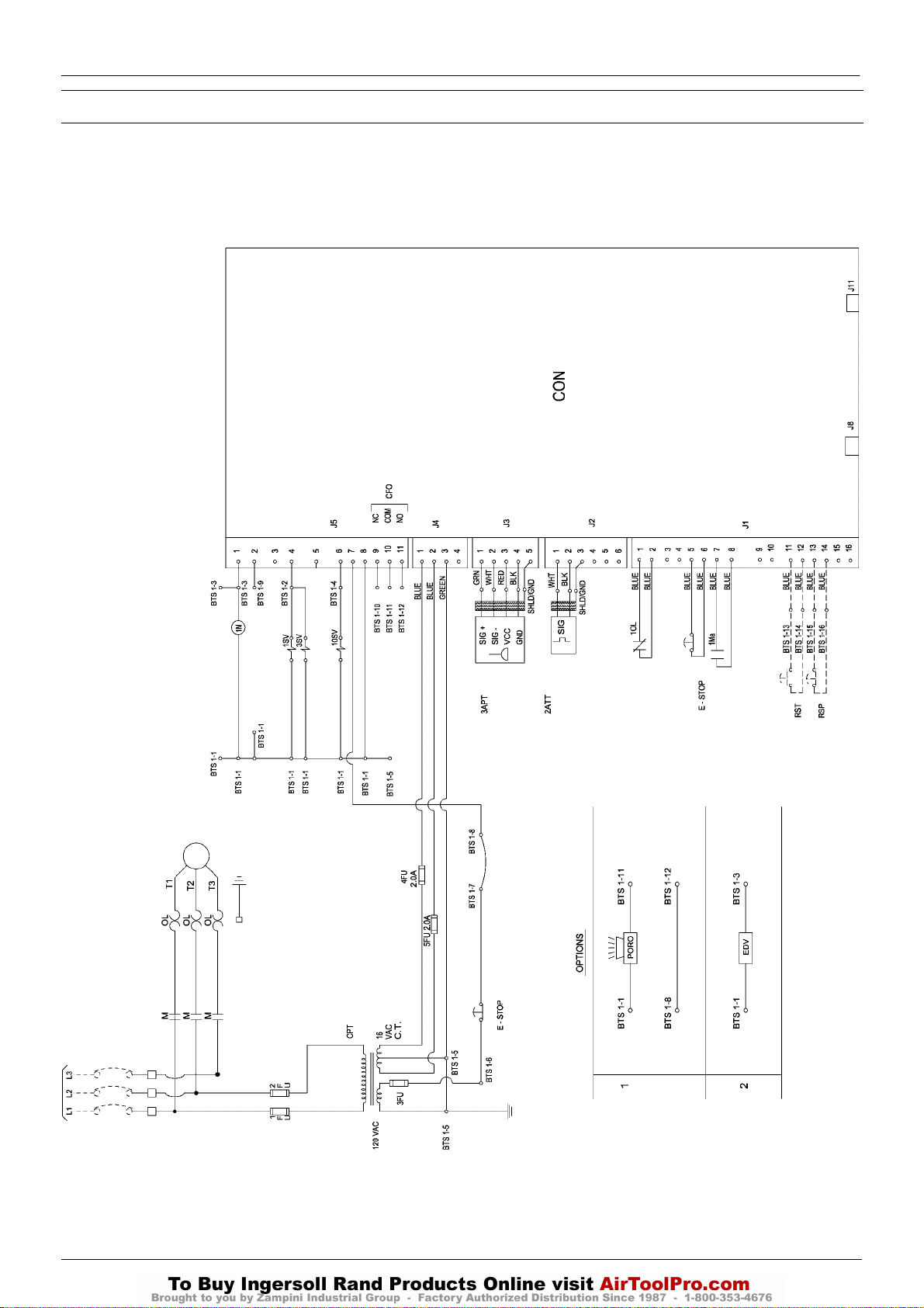
ELECTRICAL SCHEMATIC – DOL WITH INTELLISYS CONTROL
INTELLISYS OPTION
INTELLISYS – DOL
32343956
Revision D

KEY
http:/air.ingersollrand.com
UP6 15, UP6 20, UP6 25, UP6 30
INTELLISYS OPTION
13
CON Controller, INTELLISYS
CPT Transformer, control
EDV Valve, electric drain
E–STOP Button, emergency stop
FU Fuse
M Contactor (main)
1M Coil, motor starter
OL Overload, motor starter
1SV Valve, solenoid (load) N.C
3SV Valve, solenoid (blowdown) N.O
10SV Valve, solenoid (line / sump) N.C
RST Remote start
(Optional)
RSP Remote stop
(Optional)
CFO Common fault output
PORO Power out restart (Optional)
2ATT Temperature sensor
3APT Pressure sensor
NOTES
1. Approved fused disconnect or circuit breaker per code
requirements must be provided by customer.
2. Dashed lines represent wiring by customer.
3. Sizing of electrical components not supplied by Ingersoll Rand is
the responsibility of the customer and should be done in
accordance with the information on the compressor data plate
and local electrical codes.
4. Unit will not restart automaticlly after power outage, except with
additional PORO option.
5. Circuit shown in normal position de–energized.
6. All wiring to be in accordance with local codes.
14
UP6 15, UP6 20, UP6 25, UP6 30
http:/air.ingersollrand.com
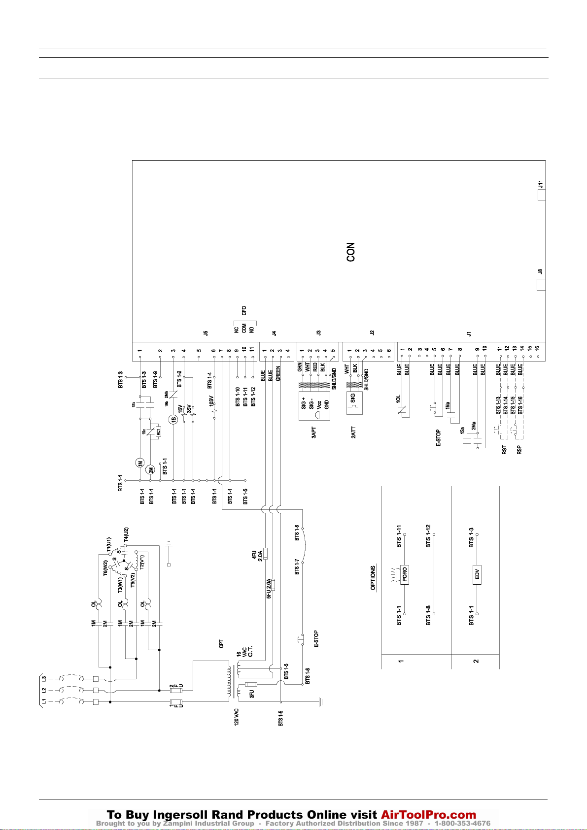
ELECTRICAL SCHEMATIC – STAR DELTA WITH INTELLISYS CONTROL
INTELLISYS OPTION
INTELLISYS – STAR DELTA
32343931
Revision E

KEY
http:/air.ingersollrand.com
UP6 15, UP6 20, UP6 25, UP6 30
INTELLISYS OPTION
15
CON Controller, INTELLISYS
CPT Transformer, control
EDV Valve, electric drain
E–STOP Button, emergency stop
FU Fuse
1M Contactor (main)
2M Contactor (delta)
OL Overload, motor starter
1SV Valve, solenoid (load) N.C
3SV Valve, solenoid (blowdown) N.O
10SV Valve, solenoid (line / sump) N.C
RST Remote start
(Optional)
RSP Remote stop
(Optional)
CFO Common fault output
PORO Power out restart (Optional)
2ATT Temperature sensor
3APT Pressure sensor
1S Contactor (wye / star)
NOTES
1. Approved fused disconnect or circuit breaker per code
requirements must be provided by customer.
2. Dashed lines represent wiring by customer.
3. Sizing of electrical components not supplied by Ingersoll Rand is
the responsibility of the customer and should be done in
accordance with the information on the compressor data plate
and local electrical codes.
4. Unit will not restart automaticlly after power outage, except with
additional PORO option.
5. Circuit shown in normal position de–energized.
6. All wiring to be in accordance with local codes.
7. Blue – 16 Volts AC
16
UP6 15, UP6 20, UP6 25, UP6 30
http:/air.ingersollrand.com
INTELLISYS OPTION
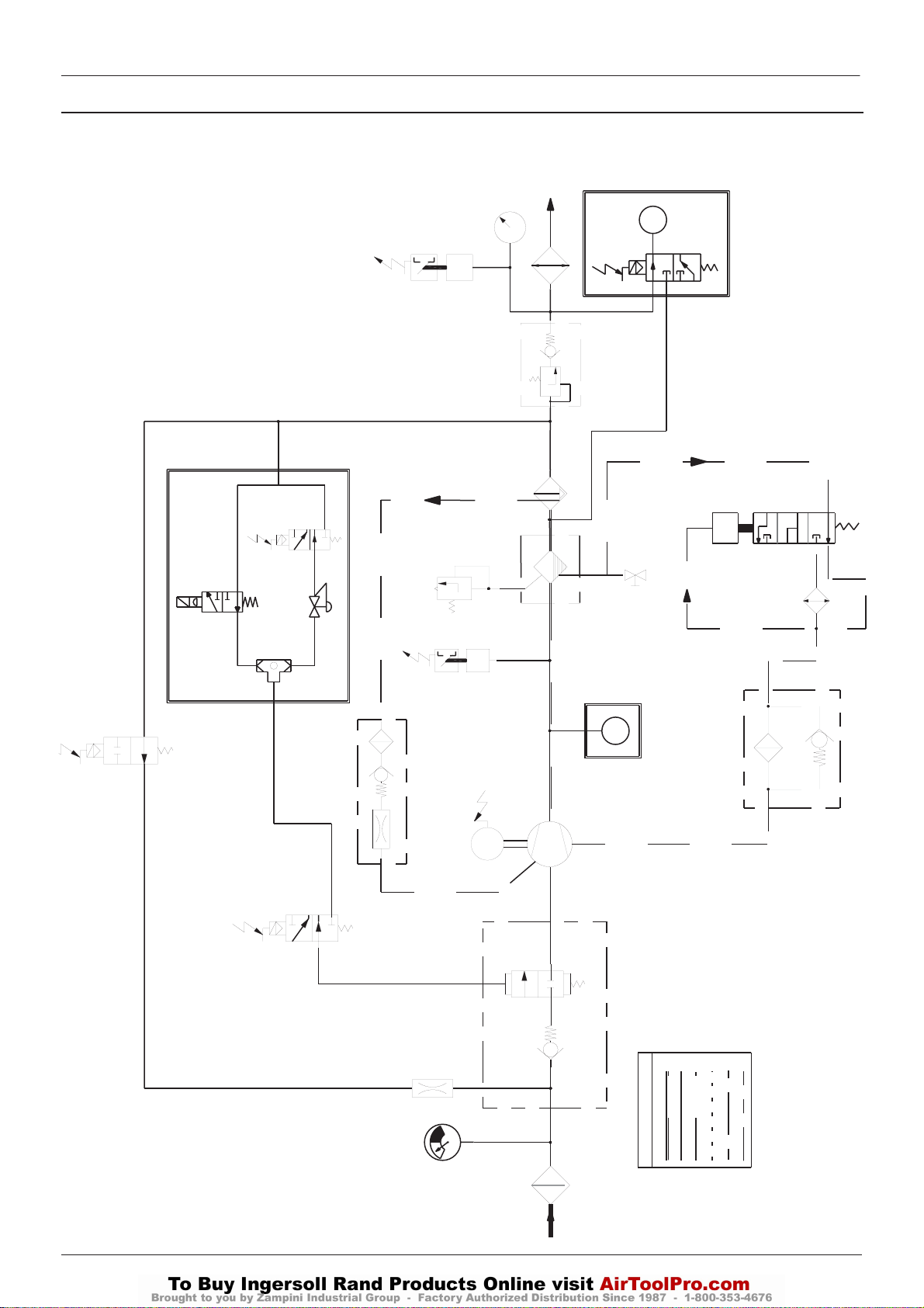
PIPING AND INSTRUMENTATION WITH INTELLISYS CONTROL
6SV
33
32
10SV
85584282
Revision D
INTELLISYS (OPTION)
REPLACES 10 AND 11
5SV
10
CONTINUED IN NEXT PAGE
11
P
39
9
8
7
T
6
40
42
41
17
18
12
T
14
15
3SV
20
19
MODULATION (OPTION)
3
1SV
16
5
21
4
M
34
INTELLISYS (OPTION)
REPLACES 12
B
A
2
PIPING LEGEND
13
F
E
C
D
22
1
INTELLISYS OPTION
http:/air.ingersollrand.com
UP6 15, UP6 20, UP6 25, UP6 30
17
FROM PREVIOUS PAGE
KEY
1. Filter, air
2. Valve, inlet
3. Valve, solenoid (load)
4. Airend assembly
5. Motor
6. Tank, separator, Coarse
7. Separator, Fine
8. Valve, minimum pressure
9. Aftercooler
10.Gauge, pressure
11.Switch, discharge pressure
12.Switch, temperature
13.Filter, coolant
14.Thermostat
15.Cooler
16.Relay, overload Motor
17. Valve, safety
18 . Valve, Drain
19 . Screen, Scavenge
20 . Valve, Solenoid 3sv (Blowdown)
21 . Orifice
22 . Indicator, Air Filter Restriction
23 .Refrigerant Compressor
24.Evaporator
25 .Condenser
27
26
M
35
24
37 38
23
29
25
36
28
INTEGRAL DRYER (OPTION)
26.Filter, Refrigerant
27.Expansion Valve
28 .Indicator, Dew Point
29.Condensate Drain Valve
30.Receiver, Air
31.Auto Drain Valve
32.Valve, Solenoid 10sv (Line/Sump)
33.Transducer, Pressure
34.Sensor, Temperature
35.Moisture Separator
36.Filter, Air
37.3 Way Valve, Bypass
38.Valve, Isolation
39.Valve, Solenoid 5sv (Modulation)
40.Valve, Solenoid 6sv (Modulation)
41.Valve, Shuttle
42.Valve, Modulation
A Air/Coolant
B Air
C Coolant
D Condensate
E Component boundary
F Refrigerant
G Option
30
31
AIR RECEIVER (OPTION)
18
UP6 15, UP6 20, UP6 25, UP6 30
http:/air.ingersollrand.com
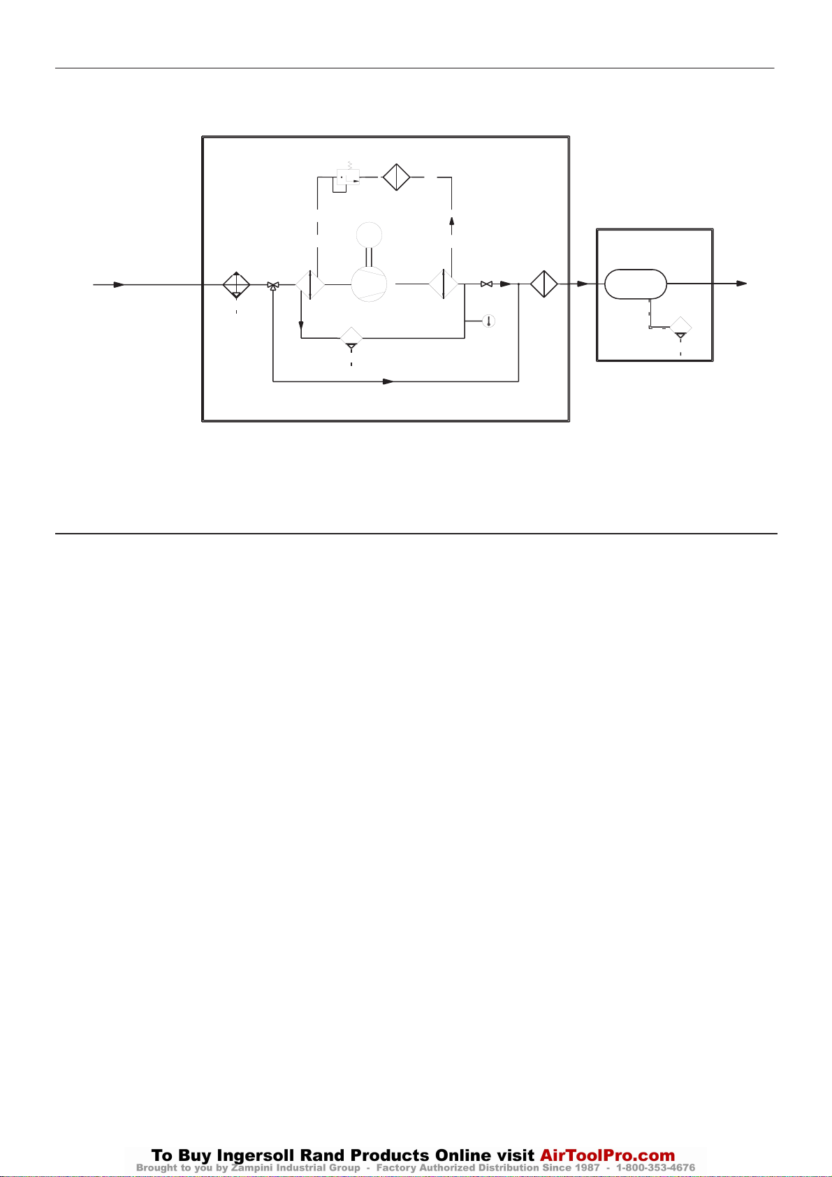
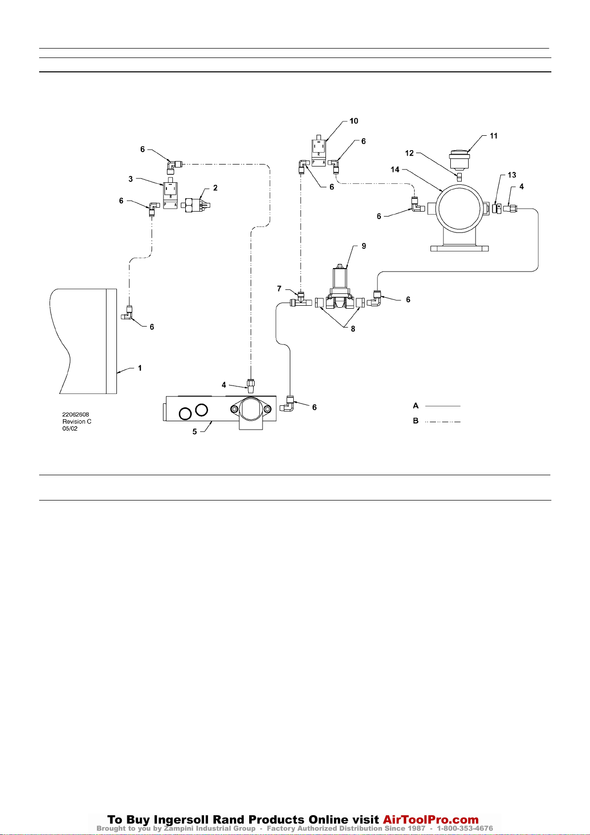
INTELLISYS CONTROL AND INSTRUMENTATION DIAGRAM
INTELLISYS OPTION
KEY
1. Tank, separator
2. Transducer, pressure
3. Valve, solenoid (Line / Sump)
4. Connector
5. Combination block
6. Elbow
7. Tee, male run
8. Reducer bushing
9. Valve, solenoid (Blowdown)
10.Valve, solenoid (Load)
11.Indicator air filter
12.Nipple
13.Adaptor
14.Intake valve assembly
NOTES:
A. Tubing 3/8 inch
B. Tubing 1/4 inch
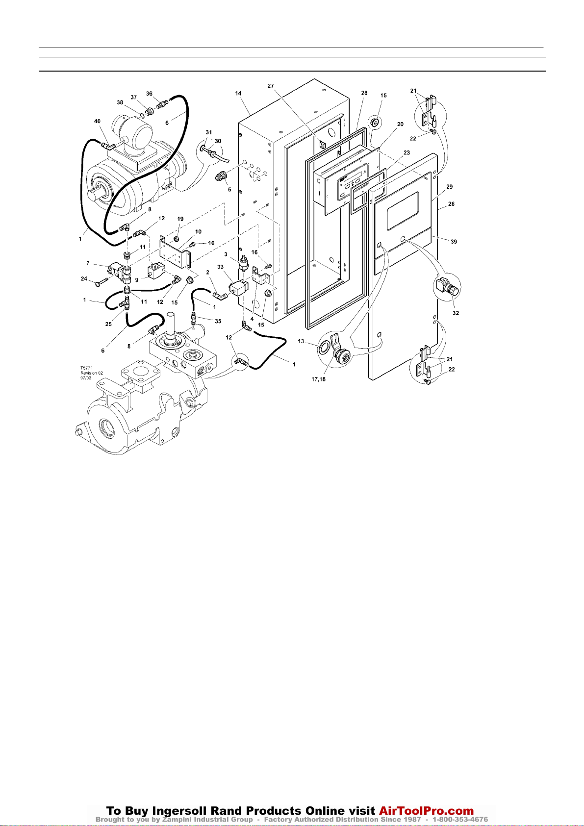
INTELLISYS PARTS – INSTRUMENTATION AND ELECTRICAL SYSTEM
http:/air.ingersollrand.com
UP6 15, UP6 20, UP6 25, UP6 30
INTELLISYS OPTION
19
Item ccn Qty. Description Item ccn Qty. Description
1 39124813 AR Tube (Nylon)
2 39155460 1 Elbow
3 39853809 1 Transducer
4 22107833 1 Bracket
5 92877018 5 Gland, cable
6 39124821 AR Tube (Nylon)
7 54654652 1 Valve, solenoid (Blowdown)
8 39155650 2 Elbow
9 54774302 1 Valve, solenoid (Load)
10 54755426 1 Bracket
11 95944625 2 Bushing
12 39155577 4 Elbow
13 93492072 2 Seal
14 22177174 1 Cabinet
15 96737564 14 Nut
16 96743182 8 Screw
17 85584340 4 Latch
*18 92829308 1 Key
19 96703756 2 Nut
20 22128763 1 Controller, INTELLISYS
21 22091193 2 Hinge
22 96743992 4 Screw
23 39495874 1 Gasket
24 96742754 2 Screw
25 22055909 1 Tee
26 22177190 1 Cabinet door
27 39133467 3 Mount
28 22177315 1 Gasket, door
29 22131155 1 Decal, controller
30 22137848 1 Sensor, temperature
31 39404157 1 ‘O’ Ring
32 22113344 1 Button, emergency stop
33 22289797 1 Valve, solenoid (line/sump)
*34 39192000 4 Grommet
35 39156393 1 Connector
36 39156419 1 Connector
37 54774997 1 Bush
38 39404165 1 ‘O’ Ring
39 22131148 1 Decal
40 39155478 1 Elbow
* Not illustrated
20
UP6 15, UP6 20, UP6 25, UP6 30
http:/air.ingersollrand.com
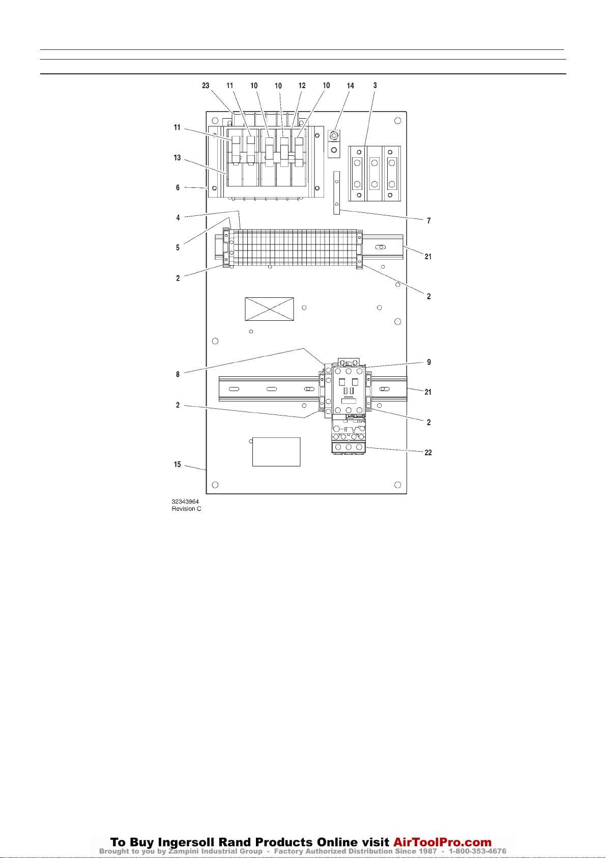
INTELLISYS PARTS – C37 FULL VOLTAGE – DOL 60Hz – 575V 15/30hp
INTELLISYS OPTION
Item ccn Qty. Description Item ccn Qty. Description
1–
2 39252937 4 Block, end stop
3 39164520 1 Block, terminal
4 39252903 27 Block, terminal
5 39252911 1 Block, terminal ground
6 22114623 1 Bracket
7 32342115 1 Bus, grounding
8 22132963 1 Contact, auxilliary
9 39251061 1 Contactor – C37
10 22074033 3 Fuse
2.0A 125–250V
11 32342099 2 Fuse
1.5A 600V
12 39479035 1 Fuse, holder
13 39480504 1 Fuse, holder
14 32342123 1 Lug, power grounding
15 22113351 1 Panel
*16 39191648 1 Plug
11 position
*17 39191655 1 Plug
16 position
*18 39186101 1 Plug
4 position
*19 39191630 1 Plug
5 position
*20 39186093 1 Plug
6 position
21 22056741 2 Rail
22 23053754 1 Relay, overload
23 39491519 1 Transformer
* Not illustrated
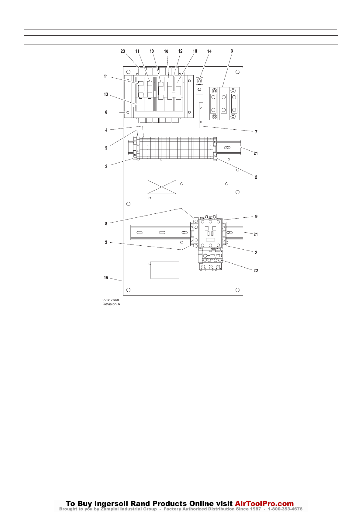
INTELLISYS PARTS – C43 FULL VOLTAGE – DOL 60Hz – 230/460V 15hp
http:/air.ingersollrand.com
UP6 15, UP6 20, UP6 25, UP6 30
INTELLISYS OPTION
21
Item ccn Qty. Description Item ccn Qty. Description
1–
2 39252937 4 Block, end stop
3 39164520 1 Block, terminal
4 39252903 27 Block, terminal
5 39252911 1 Block, terminal ground
6 22114623 1 Bracket
7 32342115 1 Bus, grounding
8 22132963 1 Contact, auxilliary
9 39250998 1 Contactor – C43
10 22074033 3 Fuse
2.0A 125–250V
11 32342099 2 Fuse
1.5A 600V
12 39479035 1 Fuse, holder
13 39480504 1 Fuse, holder
14 32342123 1 Lug, power grounding
15 22113351 1 Panel
*16 39191648 1 Plug
11 position
*17 39191655 1 Plug
16 position
*18 39186101 1 Plug
4 position
*19 39191630 1 Plug
5 position
*20 39186093 1 Plug
6 position
21 22056741 2 Rail
22 23053754 1 Relay, overload
23 39491519 1 Transformer
* Not illustrated
22
UP6 15, UP6 20, UP6 25, UP6 30
http:/air.ingersollrand.com
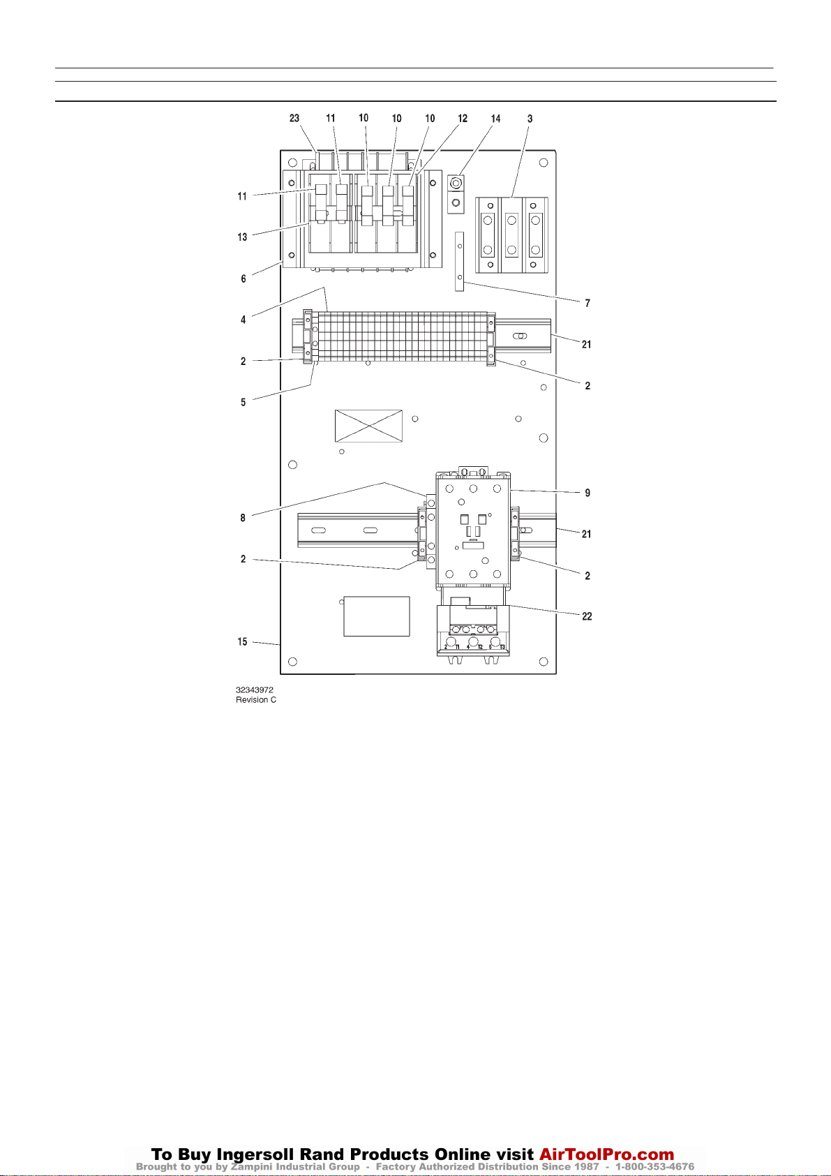
INTELLISYS PARTS – C85 FULL VOLTAGE – DOL 60Hz – 200V 15–25hp / 230/460 20–30hp
INTELLISYS OPTION
Item ccn Qty. Description Item ccn Qty. Description
1–
2 39252937 4 Block, end stop
3 39164520 1 Block, terminal
4 39252903 27 Block, terminal
5 39252911 1 Block, terminal ground
6 22114623 1 Bracket
7 32342115 1 Bus, grounding
8 22132963 1 Contact, auxilliary
9 39251020 1 Contactor – C85
10 22074033 3 Fuse
2.0A 125–250V
11 32342099 2 Fuse
1.5A 600V
12 39479035 1 Fuse, holder
13 39480504 1 Fuse, holder
14 32342123 1 Lug, power grounding
15 22113351 1 Panel
*16 39191648 1 Plug
11 position
*17 39191655 1 Plug
16 position
*18 39186101 1 Plug
4 position
*19 39191630 1 Plug
5 position
*20 39186093 1 Plug
6 position
21 22056741 2 Rail
22 23053770 1 Relay, overload
23 39491519 1 Transformer
* Not illustrated
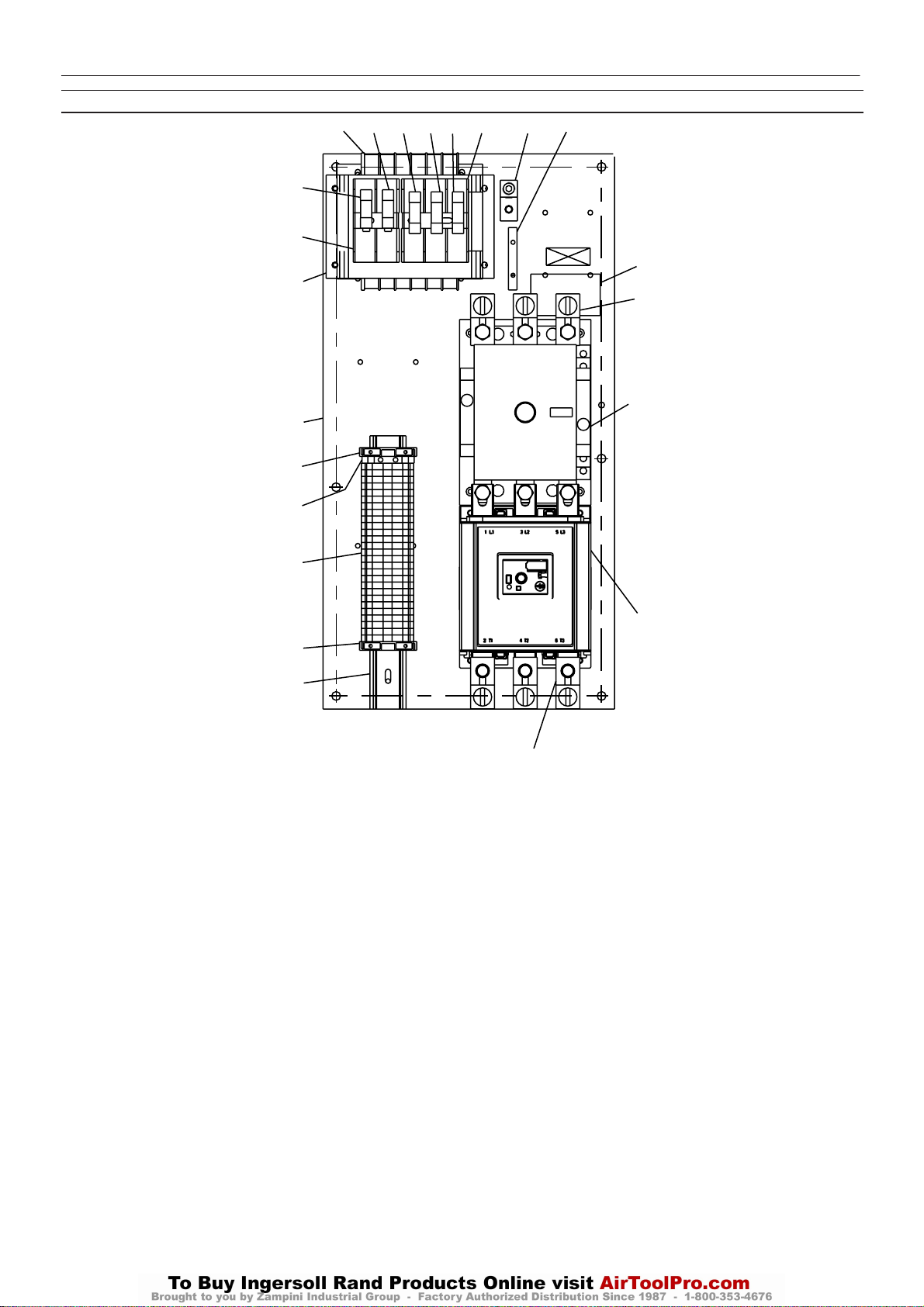
INTELLISYS PARTS – D110 FULL VOLTAGE – DOL 60Hz – 200V 30hp
http:/air.ingersollrand.com
UP6 15, UP6 20, UP6 25, UP6 30
10
24
10
12
6
16
2
9
9
9
INTELLISYS OPTION
11
7
15
13
5
8
23
3
4
23
2
22
Revision D
Item ccn Qty. Description Item ccn Qty. Description
*1 22113344 1
2 39252937 2 Block, end stop
3 39252937 1 Block, terminal ground
4 39252903 27 Block, terminal
5 22630727 1 Kit, terminal
6 22114623 1 Bracket
7 32342115 1 Bus, grounding
8 22264873 1 Contactor – D110
9 22074033 3 Fuse
10 32342099 2 Fuse
11 39479035 1 Fuse, holder
12 39480504 1 Fuse, holder
13 1 Label
Assembly, emergency stop
push button
2.0A 125–250V
1.5A 600V
532343980
*14 39191648 1 Plug
11 pos ition
15 32342123 1 Lug, power grounding
16 22050140 1 Panel
11 pos ition
*17 39191655 1 Plug
16 position
*18 39186101 1 Plug
4position
*19 39191630 1 Plug
5position
*20 39186093 1 Plug
6position
22 22056741 1 Rail
23 39251095 1 Relay,overload
24 39491519 1 Transformer
* Not illustrated
24
UP6 15, UP6 20, UP6 25, UP6 30
http:/air.ingersollrand.com
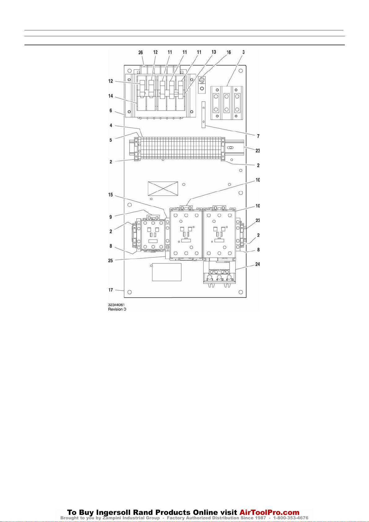
INTELLISYS PARTS – C60/C43 STAR/DELTA – 60Hz – 200V 25/30hp, 220/230V – 30hp
INTELLISYS OPTION
Item ccn Qty. Description Item ccn Qty. Description
1–
2 39252937 4 Block, end stop
3 39164520 1 Block, terminal
4 39252903 29 Block, terminal
5 39252911 1
6 22114623 1 Bracket
7 32342115 1 Bus, grounding
8 22132963 2 Contact, auxilliary
9 39250998 1 Contactor – C43
10 39251004 2 Contactor – C60
11 22074033 3 Fuse
12 32342099 2 Fuse
13 39479035 1 Fuse, holder
14 39480504 1 Fuse, holder
15 39333257 1 Interlock
Block, terminal ground
2.0A 125–250V
1.5A 600V
16 32342123 1 Lug, power grounding
17 22113351 1 Panel
*18 39191648 1 Plug
11 position
*19 39191655 1 Plug
16 position
*20 39186101 1 Plug
4 position
*21 39191630 1 Plug
5 position
*22 39186093 1 Plug
6 position
23 22056741 2 Rail
24 23053770 1 Relay, overload
25 39203443 1 Suppressor
26 39491519 1 Transformer
* Not illustrated
INTELLISYS OPTION
http:/air.ingersollrand.com
UP6 15, UP6 20, UP6 25, UP6 30
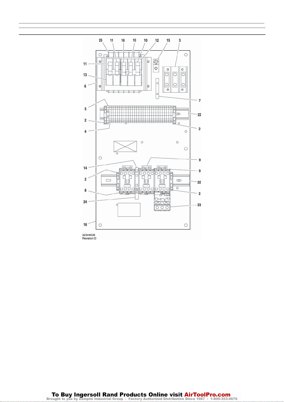
INTELLISYS PARTS – C23/16 STAR/DELTA – 60Hz – 440/460V – 20/25hp, 575V – 25/30hp
25
Item ccn Qty. Description Item ccn Qty. Description
1–
2 39252937 4 Block, end stop
3 39164520 1 Block, terminal
4 39252903 30 Block, terminal
5 39252911 1 Block, terminal ground
6 22114623 1 Bracket
7 32342115 1 Bus, grounding
8 22074413 1 Contactor – C16
9 39252036 2 Contactor – C23
10 22074033 3 Fuse
2.0A 125–250V
11 32342099 2 Fuse
1.5A 600V
12 39479035 1 Fuse, holder
13 39480504 1 Fuse, holder
14 39333257 1 Interlock
15 32342123 1 Lug, power grounding
16 22113351 1 Panel
*17 39191648 1 Plug
11 position
*18 39191655 1 Plug
16 position
*19 39186101 1 Plug
4position
*20 39191630 1 Plug
5position
*21 39186093 1 Plug
6position
22 22056741 2 Rail
23 23053747 1 Relay, overload
24 39203443 1 Suppressor
25 39491519 1 Transformer
* Not illustrated
26
UP6 15, UP6 20, UP6 25, UP6 30
http:/air.ingersollrand.com
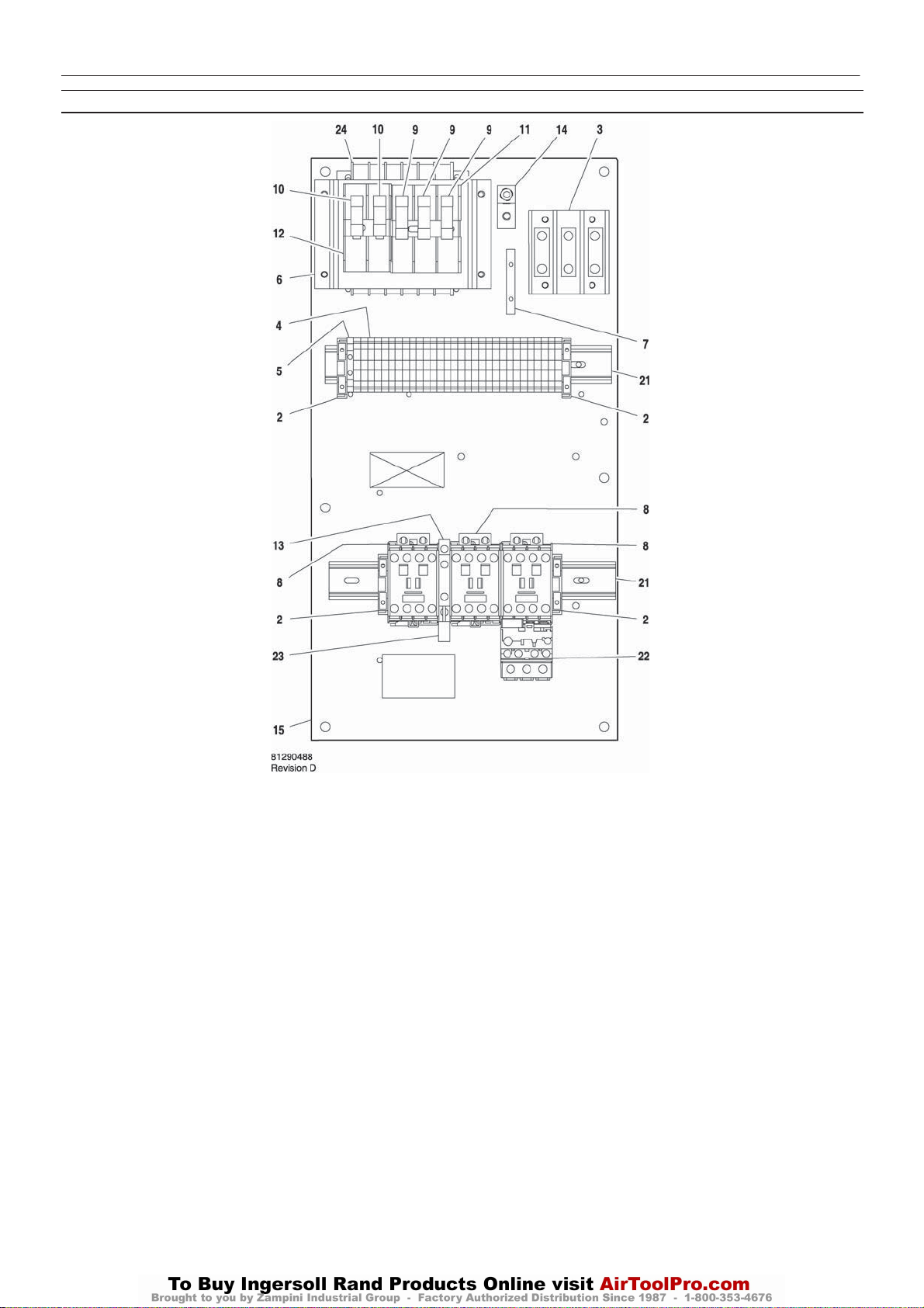
INTELLISYS PARTS – C23/23 STAR/DELTA – 60Hz – 380V 20hp
INTELLISYS OPTION
Item ccn Qty. Description Item ccn Qty. Description
1–
2 39252937 4 Block, end stop
3 39164520 1 Block, terminal
4 39252903 30 Block, terminal
5 39252911 1 Block, terminal ground
6 22114623 1 Bracket
7 32342115 1 Bus, grounding
8 39252036 3 Contactor – C23
9 22074033 3 Fuse
2.0A 125–250V
10 32342099 2 Fuse
1.5A 600V
11 39479035 1 Fuse, holder
12 39480504 1 Fuse, holder
13 39333257 1 Interlock
14 32342123 1 Lug, power grounding
15 22113351 1 Panel
*16 39191648 1 Plug
11 position
*17 39191655 1 Plug
16 position
*18 39186101 1 Plug
4position
*19 39191630 1 Plug
5position
*20 39186093 1 Plug
6position
21 22056741 2 Rail
22 23053747 1 Relay, overload
23 39203443 1 Suppressor
24 39313143 1 Transformer
* Not illustrated
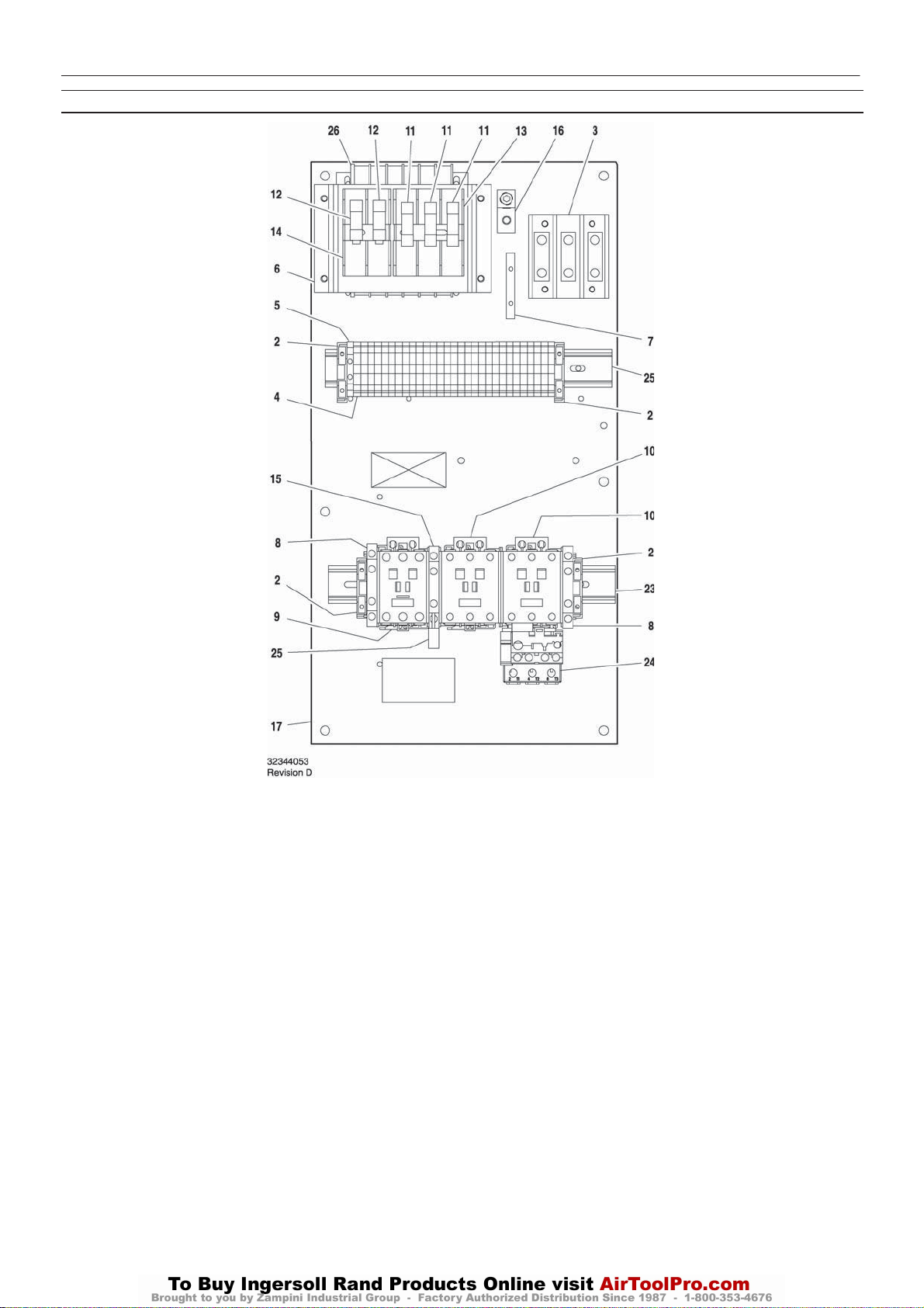
INTELLISYS PARTS – C43/37 STAR/DELTA – 60Hz – 200V 20hp, 220/230V – 25hp
http:/air.ingersollrand.com
UP6 15, UP6 20, UP6 25, UP6 30
INTELLISYS OPTION
27
Item ccn Qty. Description Item ccn Qty. Description
1–
2 39252937 4 Block, end stop
3 39164520 1 Block, terminal
4 39252903 29 Block, terminal
5 39252911 1 Block, terminal ground
6 22114623 1 Bracket
7 32342115 1 Bus, grounding
8 22132963 2 Contact, auxilliary
9 39251061 1 Contactor – C37
10 39250998 2 Contactor – C43
11 22074033 3 Fuse
2.0A 125–250V
12 32342099 2 Fuse
1.5A 600V
13 39479035 1 Fuse, holder
14 39480504 1 Fuse, holder
15 39333257 1 Interlock
16 32342123 1 Lug, power grounding
17 22113351 1 Panel
*18 39191648 1 Plug
11 position
*19 39191655 1 Plug
16 position
*20 39186101 1 Plug
4position
*21 39191630 1 Plug
5position
*22 39186093 1 Plug
6position
23 22056741 2 Rail
24 23053754 1 Relay, overload
25 39203443 1 Suppressor
26 39491519 1 Transformer
* Not illustrated

28
UP6 15, UP6 20, UP6 25, UP6 30
http:/air.ingersollrand.com
INTELLISYS PARTS – C37/23 STAR/DELTA – 60Hz – 220/230V – 15–20hp, 440/460V – 30hp
INTELLISYS OPTION
Item ccn Qty. Description Item ccn Qty. Description
1–
2 39252937 4 Block, end stop
3 39164520 1 Block, terminal
4 39252903 29 Block, terminal
5 39252911 1 Block, terminal ground
6 22114623 1 Bracket
7 32342115 1 Bus, grounding
8 22132963 1 Contact, auxilliary
9 39252036 1 Contactor – C23
10 39251061 2 Contactor – C37
11 22074033 3 Fuse
2.0A 125–250V
12 32342099 2 Fuse
1.5A 600V
13 39479035 1 Fuse, holder
14 39480504 1 Fuse, holder
15 39333257 1 Interlock
16 32342123 1 Lug, power grounding
17 22113351 1 Panel
*18 39191648 1 Plug
11 position
*19 39191655 1 Plug
16 position
*20 39186101 1 Plug
4position
*21 39191630 1 Plug
5position
*22 39186093 1 Plug
6position
23 22056741 2 Rail
24 23053754 1 Relay, overload
25 39203443 1 Suppressor
26 39491519 1 Transformer
220/230V & 440/460V
* Not illustrated
 Loading...