

Ingersoll-Rand M801P080BU48AA, M801P100CU48AA, M801P060AU36AA, M801P140DU60AA, M801P120DU60AA Installer's Manual
...
18-CD34D1-5-EN
INSTALLER’S GUIDE
Upflow/Horizontal — Downflow/Horizontal, Gas-Fired Furnaces,
“Fan Assisted Combustion System”
M801P040AU24AA
M801P060AU24AA
M801P060AU36AA
M801P080BU36AA
M801P080BU48AA
ALL phases of this installation must comply with
IMPORTANT — This Document is customer property and is to
remain with this unit. Please return to service
information pack upon completion of work.
M801P100BU36AA
M801P100CU48AA
M801P100CU60AA
M801P120DU60AA
M801P140DU60AA
M801P060AD24AA
M801P060AD36AA
M801P080BD45AA
M801P100CD48AA
M801P100CD60AA
M801P120DD60AA
M801P140DD60AA
NATIONAL, STATE AND LOCAL CODES
For VENT SIZING INFORMATION see:
USA —
National Fuel Gas Code ANSI Z223.1/ NFPA 54 (latest version)
CANADA—
Natural Gas Installation Code CAN/ CGA-B149.1 (latest version)
Propane Installation Code CAN/ CGA-B149.2 (latest version)
OPTIONAL ACCESSORIES
Model Number Description
BAYBASE205 Downflow subbase for downflow models
only
BAYFLTR200 External side filter rack
BAYFLTR203 Filter kit horizontal for 17.5" cabinet
BAYFLTR204 Filter kit horizontal for 21" cabinet
BAYFLTR205 Filter kit horizontal for 24.5" cabinet
BAYFLTR317 Cleanable filter for 17.5" cabinet upflow
only
BAYFLTR321 Cleanable filter for 21" cabinet upflow
only
BAYFLTR324 Cleanable filter for 24.5" cabinet upflow
only
BAYLPKT210B Propane conversion kit
BAYLPSS210B LP kit with stainless steel burners
BAYRACK960A Internals filter rack kit for upflow models
BAYVENT800B Masonry chimney vent kit for upflow only
KIT09224 Filter clip kit
BAYBRCKFLT10 Downflow bracket kit
FLR01185 Filter for 14-1/2" cabinet downflow only
FLR01186 Filter for 17-1/2", 21", 24-1/2" cabinet
downflow only
Upflow/ Horizontal* Downflow/ Horizontal*
*Horizontal Conversion for these furnaces may be left
or right side rotation.
A341789P12
INSTALLER’S GUIDE
WARNING
SAFETY SECTION
The following safety practices and precautions must be followed
during the installation, servicing, and operation of this furnace.
1. Use only with the type of gas approved for this furnace.
Refer to the furnace rating plate.
2. Install this furnace only in a location and position as
specied in “Location and Clearances” in this document.
3. Provide adequate combustion and ventilation air to the
furnace space as specied in “Air for Combustion and
Ventilation” in this document.
4. Combustion products must be discharged outdoors.
Connect this furnace to an approved vent system only, as
specied in the “Venting” section in this document.
5. Never test for gas leaks with an open ame. Use a
commercially available soap solution made specically
for the detection of leaks to check all connections, as
specied in “Gas Piping” in this document.
6. Always install the furnace to operate within the furnace’s
intended temperature-rise range with a duct system
which has an external static pressure within the allowable
range, as specied on the unit rating plate. Airow with
temperature rise for CFM versus static is shown in this
document.
7. When a furnace is installed so that supply ducts carry
air circulated by the furnace to areas outside the space
containing the furnace, the return air shall also be handled
by a duct(s) sealed to the furnace casing and terminating
outside the space containing the furnace.
8. A gas-red furnace for installation in a residential
garage must be installed as specied in “Location and
Clearances” section in this document.
9. The furnace may be used for temporary heating of
buildings or structures under construction only when the
following conditions have been met:
a. The furnace venting system must be complete and
installed per manufacturer’s instructions.
b. The furnace is controlled only by a room thermostat
(no eld jumpers).
c. The furnace return air duct must be complete and
sealed to the furnace and clean air lters are in place.
d. The furnace input rate and temperature rise must be
veried to be within nameplate marking.
e. 100% of the furnace combustion air requirement must
come from outside the structure.
f. The furnace return air temperature range is between
55 and 80 degrees Fahrenheit.
g. Clean the furnace, duct work, and components upon
substantial completion of the construction process,
and verify furnace operating conditions including
ignition, input rate, temperature rise and venting,
according to the manufacturer’s instructions.
10. This product must be gas piped by a Licensed Plumber
or Gas Fitter in the Commonwealth of Massachusetts.
Safety signal words are used to designate a degree or level of
seriousness associated with a particular hazard. The signal
words for safety markings are WARNING and CAUTION.
b. WARNING indicates a potentially hazardous
situation which, if not avoided, could result in death
or serious injury.
c. CAUTION indicates a potentially hazardous situation
which, if not avoided, may result in minor or moderate
injury. It is also used to alert against unsafe practices
and hazards involving only property damage.
GENERAL INSTALLATION INSTRUCTIONS
The manufacturer assumes no responsibility for equipment
installed in violation of any code or regulation. It is recommended
that Manual J of the Air Conditioning Contractors Association
(ACCA) or A.R.I. 230 be followed in estimating heating
requirements. When estimating heating requirements for
installation at Altitudes above 2000 ft., remember the gas input
must be reduced (See GAS INPUT ADJUSTMENT).
Material in this shipment has been inspected at the factory
and released to the transportation agency without known
damage. Inspect exterior of carton for evidence of rough
handling in shipment. Unpack carefully after moving
equipment to approximate location. If damage to contents
is found, report the damage immediately to the delivering
agency.
Codes and local utility requirements governing the installation of
gas red equipment, wiring, plumbing, and ue connections must
be adhered to. In the absence of local codes, the installation must
conform with latest edition of the National Fuel Gas Code ANSI
Z223.1 • National Installation Code, CAN/CGA B149.1. The
latest code may be obtained from the American Gas Association
Laboratories, 400 N. Capitol St. NW, Washington D.C. 20001,
1-800-699-9277 or www.aga.org
These furnaces have been classied as Fan Assisted Combustion
system CATEGORY I furnaces as required by ANSI Z21.47
“latest edition” and CAN/CGA 2.3. Therefore they do not require
any special provisions for venting other than what is indicated in
these instructions.
!
▲
FIRE OR EXPLOSION HAZARD
Failure to follow the safety warnings exactly could
result in serious injury, death or property damage.
Improper servicing could result in dangerous
operation, serious injury, death, or property
damage.
© 2015 Ingersoll Rand — All Rights Reserved 18-CD34D1-5-EN

WARNING
INSTALLER’S GUIDE
!
▲
CARBON MONOXIDE POISONING HAZARD
Failure to follow the steps outlined below for
each appliance connected to the venting system
being placed into operation could result in carbon
monoxide poisoning or death.
The following steps shall be followed for each appliance
connected to the venting system being placed into
operation, while all other appliances connected to the
venting system are not in operation:
Seal any unused openings in the venting
system.
1. Inspect the venting system for proper size and
horizontal pitch, as required in the National Fuel Gas
Code, ANSI Z223.1/NFPA 54 or the CAN/CGA B149
Installation Codes and these instructions. Determine
that there is no blockage or restriction, leakage,
corrosion and other deficiencies which could cause
an unsafe condition.
2. As far as practical, close all building doors and
windows and all doors between the space in which
the appliance(s) connected to the venting system are
located and other deficiencies which could cause an
unsafe condition.
3. Close fireplace dampers.
4. Turn on clothes dryers and any appliance not
connected to the venting system. Turn on any exhaust
fans, such as range hoods and bathroom exhausts,
so they are operating at maximum speed. Do not
operate a summer exhaust fan.
5. Follow the lighting instructions. Place the appliance
be-ing inspected into operation. Adjust the thermostat
so appliance is operating continuously.
6. If improper venting is observed during any of the
above tests, the venting system must be corrected
in accordance with the National Fuel Gas Code,
ANSI Z221.1/NFPA 54 and/or CAN/CGA B149
Installation Codes.
7. After it has been determined that each appliance
connected to the venting system properly vents where
tested as outlined above, return doors, windows,
exhaust fans, fireplace dampers and any other gas
-fired burning appliance to their previous conditions
of use.
Contents
Safety Section ..................................................................2
General Installation Instructions ....................................... 2
Location and Clearances .................................................. 4
Outline Drawings ..............................................................5
Upflow Installation ............................................................7
Downflow Installation ........................................................ 7
Horizontal Installation ....................................................... 7
Air for Combustion and Ventilation .................................... 8
Duct Connections ........................................................... 10
Return Air Filter .............................................................. 11
General Venting Instructions ........................................... 12
Venting into a Masonry Chimney .................................... 13
Field Wiring Diagrams .................................................... 15
Electrical Connections .................................................... 16
Gas Piping ...................................................................... 17
Sequence of Operation ...................................................17
Start-up and Adjustment ................................................. 17
Combustion and Input Check .........................................17
High Altitude Derate .......................................................19
Lighting Instructions ....................................................... 20
Control and Safety Switch Adjustment ...........................20
Operating Information ..................................................... 20
Integrated Furnace Control Error flash Codes ................ 21
Periodic Servicing Requirements ...................................22
Airflow Tables .................................................................. 23
18-CD34D1-5-EN 3
INSTALLER’S GUIDE
CAUTION
WARNING
!
▲
To prevent shortening its service life, the furnace
should not be used as a “Construction Heater”
during the finishing phases of construction
until the requirements listed in item 9, a-g of the
safety section of this publication have been met.
Condensate in the presence of chlorides and
fluorides from paint, varnish, stains, adhesives,
cleaning compounds, and cement create a
corrosive condition which may cause rapid
deterioration of the heat exchanger.
!
WARNING
▲
These furnaces are not approved or intended for
installation in manufactured (mobile) housing,
trailers, or recreational vehicles. Failure to follow
this warning could result in property damage,
personal injury, or death.
!
CAUTION
▲
Do NOT install the furnace in a corrosive or
contaminated atmosphere.
!
WARNING
▲
Do NOT install the furnace directly on carpeting,
tile or other combustible material other than
wood flooring. For vertical downflow application,
subbase (BAYBASE205) must be used between
the furnace and combustible flooring. When the
downflow furnace is installed vertically with a
cased coil, a subbase is not required.
!
▲
EXPLOSION HAZARD!
PROPANE GAS IS HEAVIER THAN AIR AND MAY
COLLECT IN ANY LOW AREAS OR CONFINED
SPACES. IN ADDITION, ODORANT FADE MAY
MAKE THE GAS UNDETECTABLE EXCEPT WITH
A WARNING DEVICE. IF THE GAS FURNACE IS
INSTALLED IN A BASEMENT, AN EXCAVATED
AREA OR A CONFINED SPACE, IT IS STRONGLY
RECOMMENDED TO CONTACT A GAS SUPPLIER
TO INSTALL A GAS DETECTING WARNING
DEVICE IN CASE OF A GAS LEAK.
NOTE: The manufacturer of your furnace does not
test any detectors and makes no representations
regarding any brand or type of detector
LOCATION AND CLEARANCES
The location of the furnace is normally selected by the architect,
the builder, or the installer. However, before the furnace is moved
into place, be sure to consider the following requirements:
1. Is the location selected as near the chimney or vent and as
centralized for heat distribution as practical?
2. Do all clearances between the furnace and enclosure
equal or exceed the minimums stated in Clearance Table
on the Outline Drawings.
3. Is there sufcient space for servicing the furnace and other
equipment? A minimum of 24 inches front accessibility
to the furnace must be provided. Any access door or
panel must permit removal of the largest component.
4. Are there at least 3 inches of clearance between the
furnace combustion air openings in the front panel and
any closed panel or door provided?
5. Are the ventilation and combustion air openings large
enough and will they remain unobstructed? If outside
air is used, are the openings set above the highest snow
accumulation level? (See the Air for Combustion and
Ventilation section)
6. Allow sufcient height in supply plenum above the
furnace to provide for cooling coil installation, if the
cooling coil is not installed at the time of this furnace
installation.
7. A furnace shall be installed so electrical components are
protected from water.
8. If the furnace is installed in a residential garage, it must
be installed so that the burners, and the ignition source
are located not less than 18 inches above the oor and the
furnace must be located or protected to avoid physical
damage from vehicles.
4 18-CD34D1-5-EN
Ø 1-5/8” HOLE WITH PLUG
INSTALLER’S GUIDE
14-1/2" 9-5/8" 13-1/4" 13"
17-1/2" 9-5/8" 16-1/4" 16"
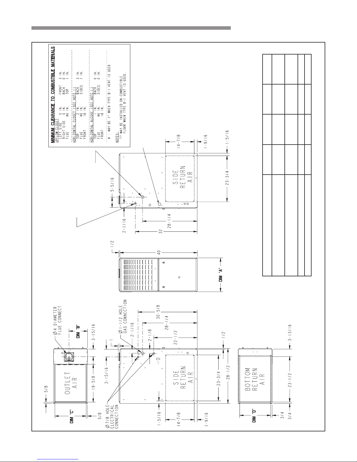
OUTLINE DRAWINGS - UPFLOW/HORIZONTAL
For the M801P Series Furnaces
Ø 7/8” HOLE WITH PLUG
ELECTRICAL CONNECTION
Ø 1-5/8” HOLE WITH PLUG
(ALTERNATE)
MODEL DIM "A" DIM "B" DIM "C" DIM "D"
M801P040AU24AA, M801P060AU24AA
M801P060AU36AA
M801P080BU36AA, M801P080BU48AA
M801P100BU36AA
M801P100CU48AA, M801P100CU60AA 21" 13-1/16" 19-3/4" 19-1/2"
M801P120DU60AA, M801P140DU60AA 24-1/2" 15-5/16" 23-1/4" 23"
18-CD34D1-5-EN 5
INSTALLER’S GUIDE
Ø 7/8” HOLE WITH PLUG
ELECTRICAL CONNECTION
(ALTERNATE)
Ø 1-5/8” HOLE WITH PLUG
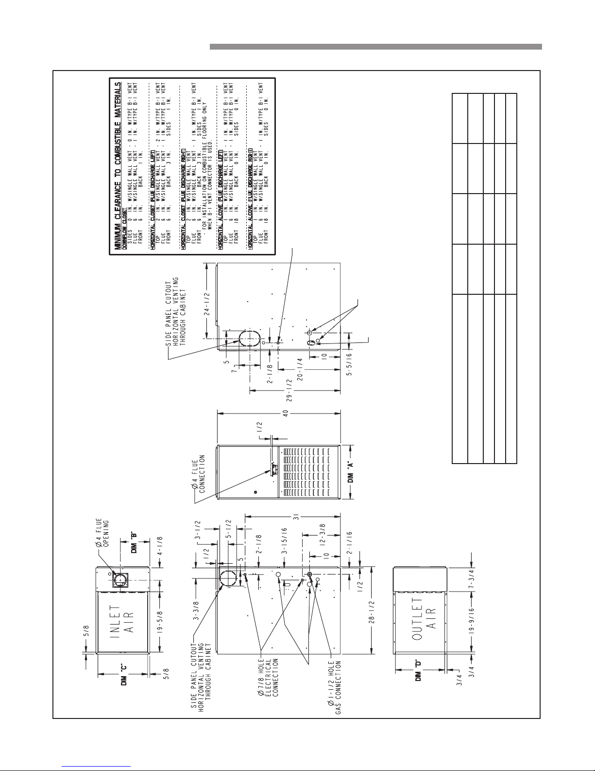
M801P OUTLINE DRAWING - DOWNFLOW\HORIZONTAL
For the M801P Series Furnaces
1-1/2” X 2-1/2” OVAL
GAS CONNECTION
MODEL DIM "A" DIM "B" DIM "C" DIM "D"
M801P060AD24AA, M801P060AD36AA 14-1/2" 9-5/8" 13-1/4" 13"
M801P080BD45AA 17-1/2" 9-5/8" 16-1/4" 16"
M801P100CD48AA, M801P100CD60AA 21" 13-1/16" 19-3/4" 19-1/2"
M801P120DD60AA, M801P140DD60AA 24-1/2" 15-5/16" 23-1/4" 23"
6 18-CD34D1-5-EN
Ø 1-5/8” HOLE
WITH PLUG (3)
UPFLOW
FURNACE
CASED
COIL
INSTALLER’S GUIDE
UPFLOW INSTALLATION
The coil is always placed downstream of the furnace airow.
Apply gasket material (duct seal eld supplied) to ALL mating
surfaces between the furnace and the coil case.
NOTE: The top flanges on the furnace must be bent
90 degrees upward to allow the coil attachment.
1
Seal with field
supplied sealant
or gasket
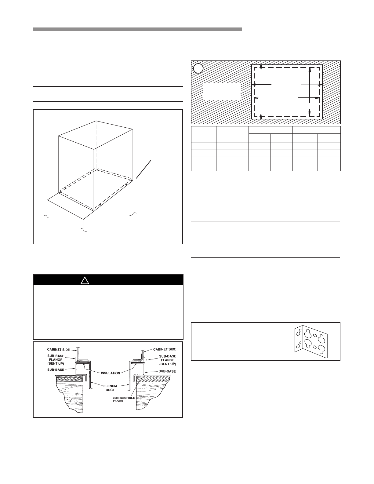
Required floor opening: (DOWNFLOW)
Figure 3 and Table 1
3
A (width)
FURNACE
FRONT
CABINET
WIDTH
14-1/2" 13-1/4" 13-5/8" 20-1/8" 12-5/8" 19-3/8"
17-1/2" 16-1/4" 16-5/8" 20-1/8" 15-5/8" 19-3/8"
21" 19-3/4" 20-1/8" 20-1/8" 19-1/8" 19-3/8"
24-1/2" 23-1/4" 23-5/8" 20-1/8" 22-5/8" 19-3/8"
RETURN
DUCT
WIDTH
FLOOR OPENING PLENUM OPENING
B (depth)
D
C
"A" "B" "C" "D"
HORIZONTAL INSTALLATION
The coil and furnace must be fully supported when used in the
horizontal position. Three brackets (with screws) are included
with downow furnaces for installation to stabilize and secure
the furnace and cased coil in the horizontal position. See Figure 4.
VERTICAL
INSTALLATIONS:
DOWNFLOW INSTALLATION
!
WARNING
▲
Do not install the furnace directly on carpeting,
tile or other combustible material other than
wood flooring. For vertical downflow application,
subbase (BAYBASE205) must be used between
the furnace and combustible flooring. When the
downflow furnace is installed vertically with a
cased coil, a subbase is not required.
2
IMPORTANT: The cased coil must be placed
downstream of the furnace. In horizontal
installations, the apex of the coil may point
either toward or away from the furnace. See the
coil Installer's Guide for more details.
The cased coil is secured to the furnace and both the furnace and
the cased coil must be properly supported. The brackets mount
using the rear screws on the coil case and use the screws provided
to secure the bracket to the furnace. The remaining bracket is
placed as close to center as possible (horizontally) between the
coil case front and the furnace bottom channel (for downow/
horizontal furnace). Use four of the screws provided to secure the
bracket. The upow furnace,
4
CASED COIL CONNECTION
BRACKET FOR DOWNFLOW
FURNACE IN HORIZONTAL
DOWNFLOW ONLY
converted to horizontal, aligns and attaches the coil as in Figure 1.
However, the coil requires additional support. This furnace may
be installed in an attic or crawl space in the horizontal position by
placing the furnace on the left or right side (as viewed from the
front in the upright position). The horizontal furnace installation
in an attic should be on a service platform large enough to allow
for proper clearances on all sides and service access to the front
of the furnace (See Clearance Table on Outline Drawings and
Figure 5).
18-CD34D1-5-EN 7
 Loading...