

Ingersoll-Rand M801P080BU48AA, M801P060AU36AA, M801P060AU24AA, M801P080BU36AA, M801P100BU36AA Service Facts
...Page 1
SERVICE FACTS
Gas Furnaces
Upflow & Downflow – Induced Draft
1 Stage Heat
Models:
M801-SF-1C
M801P040AU24AA
M801P060AU24AA
M801P060AU36AA
M801P080BU36AA
M801P080BU48AA
M801P100BU36AA
M801P100CU48AA
M801P100CU60AA
M801P120DU60AA
M801P140DU60AA
M801P060AD24AA
M801P060AD36AA
M801P080BD45AA
M801P100CD48AA
M801P100CD60AA
M801P120DD60AA
M801P140DD60AA
IMPORTANT — This document contains a wiring diagram and service information. This is customer property and is to
remain with this unit. Please return to service information pack upon completion of work.
WARNING
MODEL
TYPE
RATINGS 2
Input BTUH 3
Capacity BTUH (ICS) 3
Temp. rise (Min.-Max.) °F.
BLOWER DRIVE
Diameter - Width (In.)
No. Used
Speeds (No.)
CFM vs. in. w.g.
Motor HP
R.P.M.
Volts / Ph / Hz
COMBUSTION FAN - Type
Drive - No. Speeds
Motor HP - RPM
Volts / Ph / Hz
FLA
FILTER — Furnished?
Type Recommended
Hi Vel. (No.-Size-Thk.)
VENT — Size (in.)
HEAT EXCHANGER
Type - Fired
- Unfired
Gauge (Fired)
ORIFICES — Main
Nat. Gas. Qty. — Drill Size
L.P. Gas Qty. — Drill Size
GAS VALVE
PILOT SAFETY DEVICE
Type
BURNERS — Type
Number
POWER CONN. — V / Ph / Hz 4
Ampacity (In Amps)
Max. Overcurrent Protection (Amps)
PIPE CONN. SIZE (IN.)
DIMENSIONS
Crated (In.)
WEIGHT
Shipping (Lbs.) / Net (Lbs.)
1 Central Furnace heating designs are certified to ANSI Z21.47 / CSA 2.3.
2 For U.S. applications, above input ratings (BTUH) are up to 2,000 feet, derate 4% per 1,000 feet for elevations above 2,000 feet above sea level. For Canadian applications,
above input ratings (BTUH) are up to 4,500 feet, derate 4% per 1,000 feet for elevations above 4,500 feet above sea level.
3 Based on U.S. government standard tests.
4 The above wiring specifications are in accordance with National Electrical Code; however, installations must comply with local codes.
M801P040AU24AA
Upflow / Horizontal
40,000
31,000
30 - 60
Direct
10 x 6
See Fan Performance Table
1/5
1080
115/1/60
Centrifugal
Direct - 1
1/50 - 3180
115/1/60
1.09
No
High Velocity
1 - 16x25 - 1 in.
4 Round
Alum. Steel
20
2 — 45
2 — 56
Redundant - Single Stage
Hot Surface Ignition
Multiport Inshot
115/1/60
5.4
15
1/2
H x W x D
41-3/4 x 16-1/2 x 30-1/2
119 / 110
DISCONNECT POWER BEFORE SERVICING
PRODUCT SPECIFICATIONS
M801P060AU24AA
Upflow / Horizontal
60,000
47,000
30 - 60
Direct
1
4
See Fan Performance Table
-
2
10 x 6**
1
4
1/3
1075
115/1/60
Centrifugal
Direct - 1
1/50 - 3180
115/1/60
1.09
No
High Velocity
1 - 16x25 - 1 in.
4 Round
Alum. Steel
20
3 — 45
3 — 56
Redundant - Single Stage
Hot Surface Ignition
Multiport Inshot
3
115/1/60
9.0
15
1/2
H x W x D
41-3/4 x 16-1/2 x 30-1/2
127 / 118
1
M801P060AU36AA
Upflow / Horizontal
60,000
47,000
30 - 60
Direct
10 x 6**
1
4
See Fan Performance Table
1/3
1075
115/1/60
Centrifugal
Direct - 1
1/50 - 3180
115/1/60
1.09
No
High Velocity
1 - 16x25 - 1 in.
4 Round
Alum. Steel
20
3 — 45
3 — 56
Redundant - Single Stage
Hot Surface Ignition
Multiport Inshot
3
115/1/60
9.0
15
1/2
H x W x D
41-3/4 x 16-1/2 x 30-1/2
127 / 118
M801P080BU36AA
Upflow / Horizontal
80,000
63,000
30 - 60
Direct
10 x 7
1
4
See Fan Performance Table
1/3
1075
115/1/60
Centrifugal
Direct - 1
1/50 - 3180
115/1/60
1.09
No
High Velocity
1 - 17x25 - 1 in.
4 Round
Alum. Steel
20
4 — 45
4 — 56
Redundant - Single Stage
Hot Surface Ignition
Multiport Inshot
4
115/1/60
9.0
15
1/2
H x W x D
41-3/4 x 19-1/2 x 30-1/2
142 / 132
NOTICE: The manufacturer has a policy of continuous product and product data improvement and
reserves the right to change design and specifications without notice.
© 2013 Ingersoll Rand All Rights Reserved
04/13
Page 2

Service Facts
PRODUCT SPECIFICATIONS
MODEL
TYPE
RATINGS 2
Input BTUH 3
Capacity BTUH (ICS) 3
Temp. rise (Min.-Max.) °F.
BLOWER DRIVE
Diameter - Width (In.)
No. Used
Speeds (No.)
CFM vs. in. w.g.
Motor HP
R.P.M.
Volts / Ph / Hz
COMBUSTION FAN - Type
Drive - No. Speeds
Motor HP - RPM
Volts / Ph / Hz
FLA
FILTER — Furnished?
Type Recommended
Hi Vel. (No.-Size-Thk.)
VENT — Size (in.)
HEAT EXCHANGER
Type - Fired
- Unfired
Gauge (Fired)
ORIFICES — Main
Nat. Gas. Qty. — Drill Size
L.P. Gas Qty. — Drill Size
GAS VALVE
PILOT SAFETY DEVICE
Type
BURNERS — Type
Number
POWER CONN. — V / Ph / Hz 4
Ampacity (In Amps)
Max. Overcurrent Protection (Amps)
PIPE CONN. SIZE (IN.)
DIMENSIONS
Crated (In.)
WEIGHT
Shipping (Lbs.) / Net (Lbs.)
1 Central Furnace heating designs are certified to ANSI Z21.47 / CSA 2.3.
2 For U.S. applications, above input ratings (BTUH) are up to 2,000 feet, derate 4% per 1,000 feet for elevations above 2,000 feet above sea level. For Canadian applications,
above input ratings (BTUH) are up to 4,500 feet, derate 4% per 1,000 feet for elevations above 4,500 feet above sea level.
3 Based on U.S. government standard tests.
4 The above wiring specifications are in accordance with National Electrical Code; however, installations must comply with local codes.
MODEL
TYPE
RATINGS 2
Input BTUH 3
Capacity BTUH (ICS) 3
Temp. rise (Min.-Max.) °F.
BLOWER DRIVE
Diameter - Width (In.)
No. Used
Speeds (No.)
CFM vs. in. w.g.
Motor HP
R.P.M.
Volts / Ph / Hz
COMBUSTION FAN - Type
Drive - No. Speeds
Motor HP - RPM
Volts / Ph / Hz
FLA
FILTER — Furnished?
Type Recommended
Hi Vel. (No.-Size-Thk.)
VENT — Size (in.)
HEAT EXCHANGER
Type - Fired
- Unfired
Gauge (Fired)
ORIFICES — Main
Nat. Gas. Qty. — Drill Size
L.P. Gas Qty. — Drill Size
GAS VALVE
PILOT SAFETY DEVICE
Type
BURNERS — Type
Number
POWER CONN. — V / Ph / Hz 4
Ampacity (In Amps)
Max. Overcurrent Protection (Amps)
PIPE CONN. SIZE (IN.)
DIMENSIONS
Crated (In.)
WEIGHT
Shipping (Lbs.) / Net (Lbs.)
M801P080BU48AA
Upflow / Horizontal
80,000
64,000
30 - 60
Direct
10 x 8
1
See Fan Performance Table
Redundant - Single Stage
41-3/4 x 19-1/2 x 30-1/2
See Fan Performance Table
Redundant - Single Stage
4
1/3
1075
115/1/60
Centrifugal
Direct - 1
1/50 - 3180
115/1/60
1.09
No
High Velocity
1 - 17x25 - 1 in.
4 Round
Alum. Steel
20
4 — 45
4 — 56
Hot Surface Ignition
Multiport Inshot
4
115/1/60
9.8
15
1/2
H x W x D
142 / 132
M801P100CU60AA
Upflow / Horizontal
100,000
79,000
30 - 60
Direct
11 x 10
1
4
1/2
1075
115/1/60
Centrifugal
Direct - 1
1/50 - 3180
115/1/60
1.09
No
High Velocity
1 - 20x25 - 1 in.
4 Round
Alum. Steel
20
5 — 45
5 — 56
Hot Surface Ignition
Multiport Inshot
5
115/1/60
13.4
20
1/2
H x W x D
41-3/4 x 23 x 30-1/2
162 / 151
2 M801-SF-1C
M801P100BU36AA
See Fan Performance Table
Redundant - Single Stage
Hot Surface Ignition
41-3/4 x 19-1/2 x 30-1/2
M801P120DU60AA
See Fan Performance Table
Redundant - Single Stage
Hot Surface Ignition
41-3/4 x 26-1/2 x 30-1/2
1
Upflow / Horizontal
100,000
79,000
40 - 70
Direct
10 x 7
1
4
1/3
1075
115/1/60
Centrifugal
Direct - 1
1/50 - 3180
115/1/60
1.09
No
High Velocity
1 - 17x25 - 1 in.
4 Round
Alum. Steel
20
5 — 45
5 — 56
Multiport Inshot
5
115/1/60
9.0
15
1/2
H x W x D
151 / 141
Upflow / Horizontal
120,000
96,000
30 - 60
Direct
11 x 10
1
4
1/2
1075
115/1/60
Centrifugal
Direct - 1
1/50 - 3180
115/1/60
1.09
No
High Velocity
1 - 24x25 - 1 in.
4 Round
Alum. Steel
20
6 — 45
6 — 56
Multiport Inshot
6
115/1/60
13.4
20
1/2
H x W x D
186 / 174
M801P100CU48AA
Upflow / Horizontal
100,000
79,000
35 - 65
Direct
10 x 8
1
See Fan Performance Table
Redundant - Single Stage
M801P140DU60AA
See Fan Performance Table
Redundant - Single Stage
Hot Surface Ignition
41-3/4 x 26-1/2 x 30-1/2
4
1/2
1075
115/1/60
Centrifugal
Direct - 1
1/50 - 3180
115/1/60
1.09
No
High Velocity
1 - 20x25 - 1 in.
4 Round
Alum. Steel
20
5 — 45
5 — 56
Hot Surface Ignition
Multiport Inshot
5
115/1/60
11.6
15
1/2
H x W x D
41-3/4 x 23 x 30-1/2
162 / 151
Upflow / Horizontal
140,000
111,000
40 - 70
Direct
11 x 10
1
4
3/4
1075
115/1/60
Centrifugal
Direct - 1
1/50 - 3180
115/1/60
1.09
No
High Velocity
1 - 24x25 - 1 in.
4 Round
Alum. Steel
20
7 — 45
7 — 56
Multiport Inshot
7
115/1/60
13.8
20
1/2
H x W x D
193 / 181
Page 3

Service Facts
PRODUCT SPECIFICATIONS
MODEL
TYPE
RATINGS 2
Input BTUH 3
Capacity BTUH (ICS) 3
Temp. rise (Min.-Max.) °F.
BLOWER DRIVE
Diameter - Width (In.)
No. Used
Speeds (No.)
CFM vs. in. w.g.
Motor HP
R.P.M.
Volts / Ph / Hz
COMBUSTION FAN - Type
Drive - No. Speeds
Motor HP - RPM
Volts / Ph / Hz
FLA
FILTER — Furnished?
Type Recommended
Hi Vel. (No.-Size-Thk.)
VENT — Size (in.)
HEAT EXCHANGER
Type - Fired
- Unfired
Gauge (Fired)
ORIFICES — Main
Nat. Gas. Qty. — Drill Size
L.P. Gas Qty. — Drill Size
GAS VALVE
PILOT SAFETY DEVICE
Type
BURNERS — Type
Number
POWER CONN. — V / Ph / Hz 4
Ampacity (In Amps)
Max. Overcurrent Protection (Amps)
PIPE CONN. SIZE (IN.)
DIMENSIONS
Crated (In.)
WEIGHT
Shipping (Lbs.) / Net (Lbs.)
1 Central Furnace heating designs are certified to ANSI Z21.47 / CSA 2.3.
2 For U.S. applications, above input ratings (BTUH) are up to 2,000 feet, derate 4% per 1,000 feet for elevations above 2,000 feet above sea level. For Canadian applications,
above input ratings (BTUH) are up to 4,500 feet, derate 4% per 1,000 feet for elevations above 4,500 feet above sea level.
3 Based on U.S. government standard tests.
4 The above wiring specifications are in accordance with National Electrical Code; however, installations must comply with local codes.
MODEL
TYPE
RATINGS 2
Input BTUH 3
Capacity BTUH (ICS) 3
Temp. rise (Min.-Max.) °F.
BLOWER DRIVE
Diameter - Width (In.)
No. Used
Speeds (No.)
CFM vs. in. w.g.
Motor HP
R.P.M.
Volts / Ph / Hz
COMBUSTION FAN - Type
Drive - No. Speeds
Motor HP - RPM
Volts / Ph / Hz
FLA
FILTER — Furnished?
Type Recommended
Hi Vel. (No.-Size-Thk.)
VENT — Size (in.)
HEAT EXCHANGER
Type - Fired
- Unfired
Gauge (Fired)
ORIFICES — Main
Nat. Gas. Qty. — Drill Size
L.P. Gas Qty. — Drill Size
GAS VALVE
PILOT SAFETY DEVICE
Type
BURNERS — Type
Number
POWER CONN. — V / Ph / Hz 4
Ampacity (In Amps)
Max. Overcurrent Protection (Amps)
PIPE CONN. SIZE (IN.)
DIMENSIONS
Crated (In.)
WEIGHT
Shipping (Lbs.) / Net (Lbs.)
M801P060AD24AA
Downflow / Horizontal
60,000
48,000
35 - 65
DIRECT
10 x 7
1
See Fan Performance Table
Redundant - Single Stage
41-3/4 x 16-1/2 x 30-1/2
Downflow / Horizontal
See Fan Performance Table
Redundant - Single Stage
4
1/5
1075
115/1/60
Centrifugal
Direct - 1
1/50 - 3180
115/1/60
1.09
No
High Velocity
2 - 14x20 - 1in.
4 Round
Alum. Steel
20
3 — 45
3 — 56
Hot Surface Ignition
Multiport Inshot
3
115/1/60
5.5
15
1/2
H x W x D
129 / 119
M801P100CD60AA
100,000
80,000
30 - 60
DIRECT
11 x 10
1
4
1/2
1075
115/1/60
Centrifugal
Direct - 1
1/50 - 3180
115/1/60
1.09
No
High Velocity
2 - 16x20 - 1 in.
4 Round
Alum. Steel - Type I
20
5 — 45
5 — 56
Hot Surface Ignition
Multiport Inshot
5
115/1/60
12.8
15
1/2
H x W x D
41-3/4 x 23 x 30-1/2
167 / 155
M801-SF-1C 3
M801P060AD36AA
Downflow / Horizontal
60,000
48,000
30 - 60
DIRECT
11 x 7
1
See Fan Performance Table
Redundant - Single Stage
41-3/4 x 16-1/2 x 30-1/2
Downflow / Horizontal
See Fan Performance Table
Redundant - Single Stage
41-3/4 x 26-1/2 x 30-1/2
4
1/2
1075
115/1/60
Centrifugal
Direct - 1
1/50 - 3180
115/1/60
1.09
No
High Velocity
2 - 14x20 - 1in.
4 Round
Alum. Steel
20
3 — 45
3 — 56
Hot Surface Ignition
Multiport Inshot
3
115/1/60
11.6
15
1/2
H x W x D
129 / 119
M801P120DD60AA
120,000
96,000
35 - 65
DIRECT
11 x 10
1
4
1/2
1075
115/1/60
Centrifugal
Direct - 1
1/50 - 3180
115/1/60
1.09
No
High Velocity
2 - 16x20 - 1 in.
4 Round
Alum. Steel - Type I
20
6 — 45
6 — 56
Hot Surface Ignition
Multiport Inshot
6
115/1/60
12.8
15
1/2
H x W x D
189 / 176
1
M801P080BD45AA
Downflow / Horizontal
80,000
64,000
35 - 65
DIRECT
10 x 8
1
See Fan Performance Table
Redundant - Single Stage
41-3/4 x 19-1/2 x 30-1/2
Downflow / Horizontal
See Fan Performance Table
Redundant - Single Stage
41-3/4 x 26-1/2 x 30-1/2
4
1/3
1075
115/1/60
Centrifugal
Direct - 1
1/50 - 3180
115/1/60
1.09
No
High Velocity
2 - 14x20 - 1 in.
4 Round
Alum. Steel - Type I
20
4 — 45
4 — 56
Hot Surface Ignition
Multiport Inshot
4
115/1/60
9.1
15
1/2
H x W x D
146 / 135
M801P140DD60AA
140,000
113,000
45 - 75
DIRECT
11 x 10
1
4
3/4
1075
115/1/60
Centrifugal
Direct - 1
1/50 - 3180
115/1/60
1.09
No
High Velocity
2 - 16x20 - 1in.
4 Round
Alum. Steel
20
7 — 45
7 — 56
Hot Surface Ignition
Multiport Inshot
7
115/1/60
13.8
20
1/2
H x W x D
196 / 183
M801P100CD48AA
Downflow / Horizontal
100,000
80,000
35 - 65
DIRECT
10 x 8
1
See Fan Performance Table
Redundant - Single Stage
4
1/2
1075
115/1/60
Centrifugal
Direct - 1
1/50 - 3180
115/1/60
1.09
No
High Velocity
2 - 16x20 - 1in.
4 Round
Alum. Steel
20
5 — 45
5 — 56
Hot Surface Ignition
Multiport Inshot
5
115/1/60
11.6
15
1/2
H x W x D
41-3/4 x 23 x 30-1/2
166 / 154
Page 4
Service Facts
▲
WARNING
!
▲
CAUTION
!
▲
WARNING
!
▲
WARNING
!
CARBON MONOXIDE POISONING HAZARD
Failure to follow the steps outlined below for each
appliance connected to the venting system being
placed into operation could result in carbon monoxide
poisoning or death.
The following steps shall be followed for each appliance
connected to the venting system being placed into
operation, while all other appliances connected to the
venting system are not in operation:
1. Seal any unused openings in the venting system.
2. Inspect the venting system for proper size and
horizontal pitch, as required in the National Fuel Gas
Code, ANSI Z223.1/NFPA 54 or the CAN/CGA B149
Installation Codes and these instructions. Determine
that there is no blockage or restriction, leakage,
corrosion and other deficiencies which could cause an
unsafe condition.
3. As far as practical, close all building doors and
windows and all doors between the space in which the
appliance(s) connected to the venting system are
located and other deficiencies which could cause an
unsafe condition.
4. Close fireplace dampers.
5. Turn on clothes dryers and any appliance not
connected to the venting system. Turn on any exhaust
fans, such as range hoods and bathroom exhausts, so
they are operating at maximum speed. Do not operate
a summer exhaust fan.
6. Follow the lighting instructions. Place the appliance
being inspected into operation. Adjust the thermostat
so appliance is operating continuously.
7. If improper venting is observed during any of the above
tests, the venting system must be corrected in
accordance with the National Fuel Gas Code,
ANSI Z221.1/NFPA 54 and/or CAN/CGA B149
Installation Codes.
8. After it has been determined that each appliance
connected to the venting system properly vents where
tested as outlined above, return doors, windows,
exhaust fans, fireplace dampers and any other gas-fired
burning appliance to their previous conditions of use.
▲
WARNING
!
SEQUENCE OF OPERATION
THERMOSTAT CALL FOR HEAT
R and W thermostat contacts close signaling the control
module to run its self-check routine. After the control
module has verified that the pressure switch contacts are
open and the limit switch(es) contacts are closed, the draft
blower will be energized.
As the induced draft blower comes up to speed, the pressure
switch contacts will close and the ignitor warm up period
will begin. The ignitor will heat for approx. 17 seconds,
then the gas valve is energized to permit gas flow to the
burners. The flame sensor confirms that ignition has been
achieved within the 4 second ignition trial period.
4 M801-SF-1C
SAFETY SECTION
The cabinet must have an uninterrupted or unbroken
ground according to National Electrical Code, ANSI/NFPA
70 - “latest edition” and Canadian Electrical Code, CSA
C22.1 or local codes to minimize personal injury if an
electrical fault should occur. A failure to follow this warning could result in an electrical shock, fire, injury, or death.
The integrated furnace control is polarity sensitive. The
hot leg of the 115 VAC power must be connected to the
BLACK field lead.
FIRE OR EXPLOSION HAZARD
Failure to follow the safety warnings exactly could result
in serious injury, death or property damage.
Never test for gas leaks with an open flame. Use a commercially available soap solution made specifically for
the detection of leaks to check all connections. A fire or
explosion may result causing property damage, personal
injury, or loss of life.
FIRE OR EXPLOSION HAZARD
Failure to follow the safety warnings exactly could result
in serious injury, death or property damage.
Improper servicing could result in dangerous operation,
serious injury, death, or property damage.
After the flame sensor confirms that ignition has been
achieved, the delay to fan ON period begins timing and
after approx. 45 seconds the indoor blower motor will be
energized and will continue to run during the heating cycle.
When the thermostat is satisfied, R and W thermostat
contacts open, the gas valve will close, the flames will extinguish, and the induced draft blower will be de-energized.
The indoor blower motor will continue to run for the fan off
period (Field selectable at 60, 100, 140 or 180 seconds), then
will be de-energized by the control module.
Page 5
PERIODIC SERVICING REQUIREMENTS
▲
WARNING
!
▲
WARNING
!
▲
WARNING
!
▲
CAUTION
!
1. GENERAL INSPECTION — Examine the furnace
installation annually for the following items:
a. All flue product carrying areas external to the fur-
nace (i.e. chimney, vent connector) are clear and free
of obstruction. A vent screen in the end of the vent
(flue) pipe must be inspected for blockage annually.
b. The vent connector is in place, slopes upward and is
physically sound without holes or excessive corrosion.
c. The return air duct connection(s) is physically
sound, is sealed to the furnace and terminates outside the space containing the furnace.
d. The physical support of the furnace should be sound
without sagging, cracks, gaps, etc., around the base
so as to provide a seal between the support and the
base.
e. There are no obvious signs of deterioration of the
furnace.
2. FILTERS — Filters should be cleaned or replaced (with
high velocity filters only), monthly and more frequently
during high use times of the year such as midsummer
or midwinter.
3. BLOWERS — The blower size and speed determine the
air volume delivered by the furnace. The blower motor bearings are factory lubricated and under normal
operating conditions do not require servicing. If motor
lubrication is required it should only be done by a
qualified servicer. Annual cleaning of the blower wheel
and housing is recommended for maximum air output,
and this must be performed only by a qualified servicer
or service agency.
4. IGNITER — This unit has a special hot surface direct
ignition device that automatically lights the burners.
Please note that it is very fragile and should be handled with care.
Do not touch igniter. It is extremely hot. Failure to follow
this warning could result in severe burns.
5. BURNER — Gas burners do not normally require
scheduled servicing, however, accumulation of foreign
material may cause a yellowing flame or delayed ignition. Either condition indicates that a service call is
required. For best operation, burners must be cleaned
annually using brushes and vacuum cleaner.
Turn off gas and electric power supply. To clean burn-
ers, remove the top burner bracket. Lift burners from
orifices.
NOTE:
Be careful not to break igniter when removing burners.
Clean burners with brush and/or vacuum cleaner. Re-
assemble parts by reversal of the above procedure.
Service Facts
NOTE:
On LP (propane) units, due to variations in BTU content
and altitude, servicing may be required at shorter intervals.
CARBON MONOXIDE POISONING HAZARD
Failure to follow the installation instructions for the venting system being placed into operation could result in
carbon monoxide poisoning or death.
6. HEAT EXCHANGER/FLUE PIPE — These items must
be inspected for signs of corrosion, and/or deterioration
at the beginning of each heating season by a qualified
service technician and cleaned annually for best operation. To clean flue gas passages, follow recommendations below:
a. Turn off gas and electric power supply.
b. Inspect flue pipe exterior for cracks, leaks, holes or
leaky joints.
c. Remove burner compartment door from furnace.
d. Inspect around insulation covering flue collector box.
Inspect induced draft blower connections to the flue
pipe connection.
e. Remove burners. (See 4.)
f. Use a mirror and flashlight to inspect interior of
heat exchanger, be careful not to damage the igniter,
flame sensor or other components.
g. If any corrosion is present, contact a service agency.
Heat exchanger should be cleaned by a qualified
service technician.
h. After inspection is complete replace burners and
furnace door.
i. Restore gas supply. Check for leaks using a soap
solution. Restore electrical supply. Check unit for
normal operation.
FIRE OR EXPLOSION HAZARD
Failure to follow the safety warnings exactly could result
in serious injury, death or property damage.
Never test for gas leaks with an open flame. Use a commercially available soap solution made specifically for
the detection of leaks to check all connections. A fire or
explosion may result causing property damage, personal
injury, or loss of life.
7. COOLING COIL CONDENSATE DRAIN — If a cooling
coil is installed with the furnace, condensate drains
should be checked and cleaned periodically to assure
that condensate can drain freely from coil to drain. If
condensate cannot drain freely water damage could occur. (See Condensate Drain in Installer’s Guide)
NOTE: On LP (propane) units, some light yellow tipping of
the outer mantle is normal. Inner mantle should be bright
blue.
Natural gas units should not have any yellow tipped
flames. This condition indicates that a service call is
required. For best operation, burners must be cleaned annually using brushes and vacuum cleaner.
M801-SF-1C 5
Label all wires prior to disconnection when servicing
controls. Wiring errors can cause improper and dangerous operation.
Verify proper operation after servicing.
Page 6
Service Facts
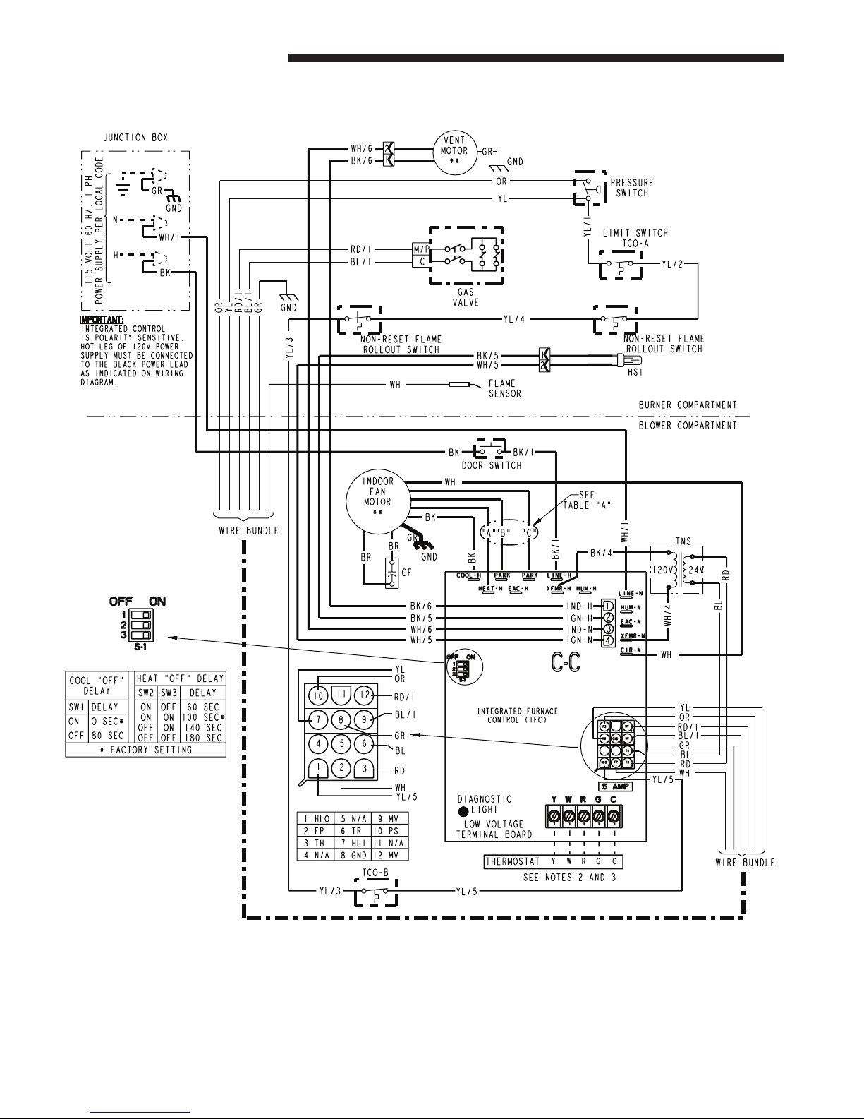
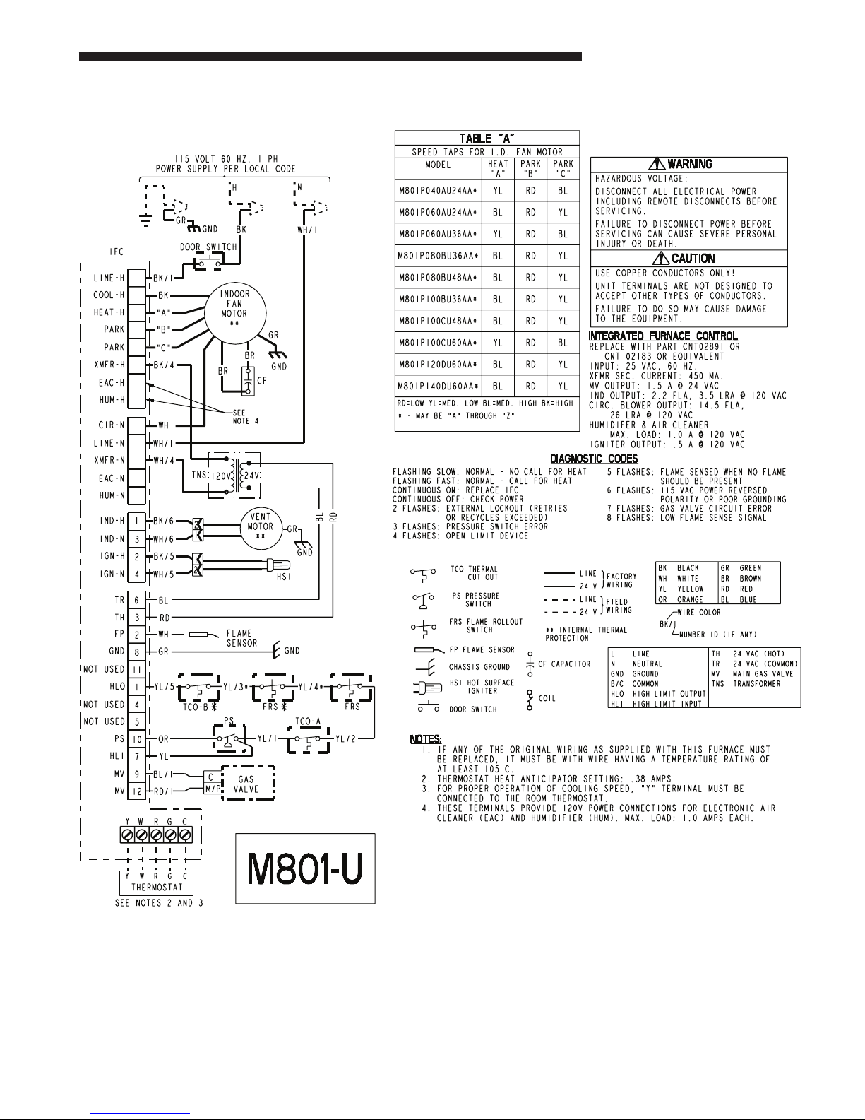
UPFLOW WIRING DIAGRAM
6 M801-SF-1C
From Dwg. D344494
(continued on next page)
Page 7
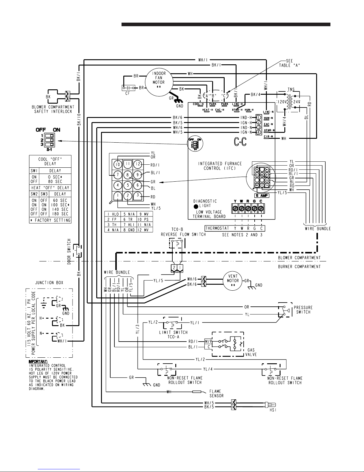
UPFLOW SCHEMATIC DIAGRAM
Service Facts
M801-SF-1C 7
From Dwg. D344494
Page 8
Service Facts
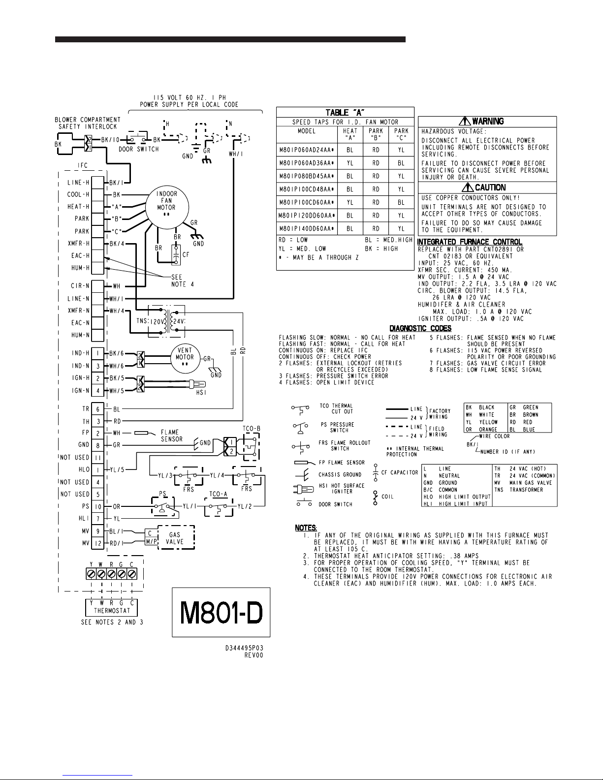
DOWNFLOW WIRING DIAGRAM
8 M801-SF-1C
From Dwg. D344495
(continued on next page)
Page 9
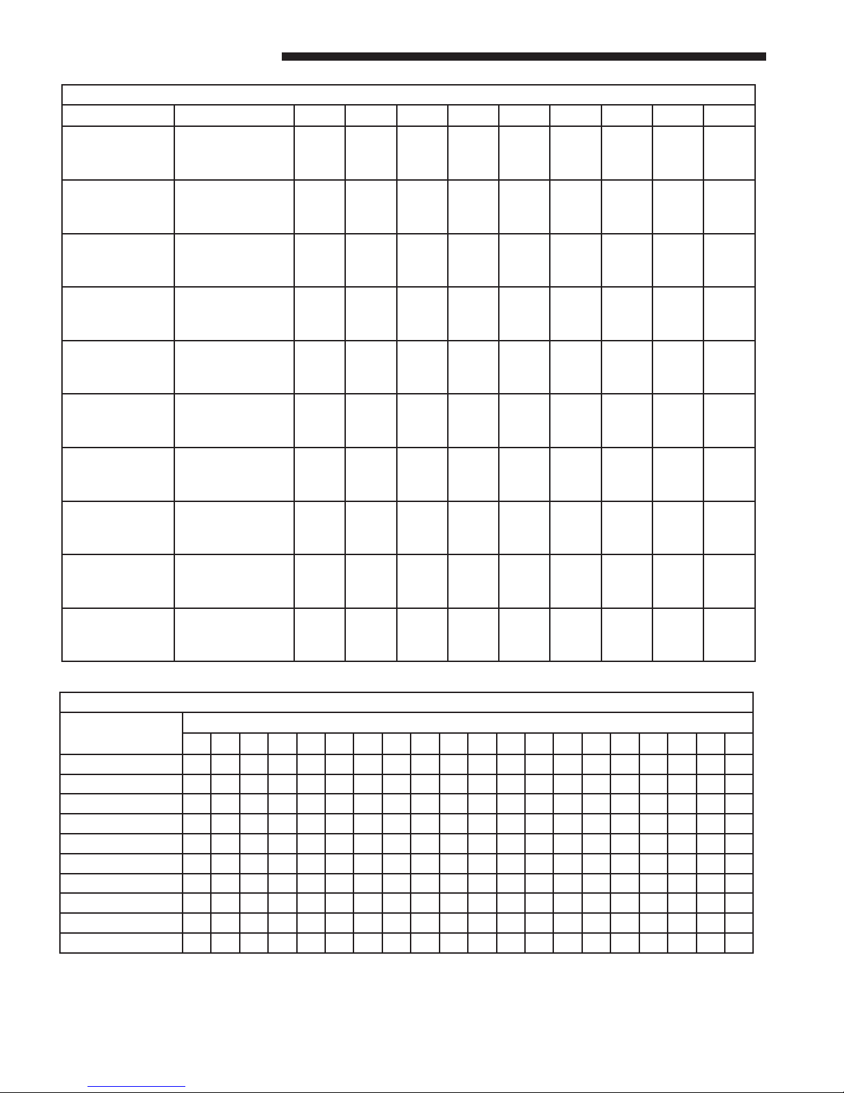
DOWNFLOW SCHEMATIC DIAGRAM
Service Facts
M801-SF-1C 9
From Dwg. D344495
Page 10
Service Facts
FURNACE AIRFLOW (CFM) VS. EXTERNAL STATIC PRESSURE (IN. W.C.)
MODEL SPEED TAP 0.10 0.20 0.30 0.40 0.50 0.60 0.70 0.80 0.90
M801P040AU24AA
M801P060AU24AA
M801P060AU36AA
M801P080BU36AA
M801P080BU48AA
M801P100BU36AA
M801P100CU48AA
M801P100CU60AA
M801P120DU60AA
M801P140DU60AA
4-HIGH - Black
3-MED - HIGH - Blue
2-MED - LOW - Yellow
1-LOW - Red
4-HIGH - Black
3-MED - HIGH - Blue
2-MED - LOW - Yellow
1-LOW - Red
4-HIGH - Black
3-MED - HIGH - Blue
2-MED - LOW - Yellow
1-LOW - Red
4-HIGH - Black
3-MED - HIGH - Blue
2-MED - LOW - Yellow
1-LOW - Red
4-HIGH - Black
3-MED - HIGH - Blue
2-MED - LOW - Yellow
1-LOW - Red
4-HIGH - Black
3-MED - HIGH - Blue
2-MED - LOW - Yellow
1-LOW - Red
4-HIGH - Black
3-MED - HIGH - Blue
2-MED - LOW - Yellow
1-LOW - Red
4-HIGH - Black
3-MED - HIGH - Blue
2-MED - LOW - Yellow
1-LOW - Red
4-HIGH - Black
3-MED - HIGH - Blue
2-MED - LOW - Yellow
1-LOW - Red
4-HIGH - Black
3-MED - HIGH - Blue
2-MED - LOW - Yellow
1-LOW - Red
1018
847
716
617
1018
835
712
611
1426
1243
1042
900
1393
1210
1046
900
1839
1323
1092
788
1476
1249
1020
873
1880
1662
1428
1208
2181
1908
1621
1443
2135
1906
1646
1423
2462
2128
1755
1450
1004
832
701
599
997
821
702
596
1389
1225
1039
903
1384
1209
1052
903
1821
1325
1090
783
1464
1257
1046
887
1846
1635
1421
1215
2143
1888
1609
1419
2101
1881
1632
1415
2407
2112
1746
1446
982
809
678
575
973
800
683
573
1345
1197
1027
895
1364
1198
1047
895
1796
1329
1091
780
1441
1252
1058
890
1799
1598
1402
1210
2104
1868
1597
1395
2066
1856
1617
1407
2351
2096
1736
1442
950
779
648
544
941
771
655
543
1298
1160
1005
877
1335
1177
1033
888
1756
1319
1083
768
1408
1234
1050
883
1740
1551
1370
1193
2053
1834
1582
1381
2036
1817
1596
1391
2284
2054
1719
1427
910
742
610
507
901
734
617
505
1236
1113
973
848
1296
1147
1008
869
1710
1308
1076
758
1363
1203
1028
864
1669
1493
1326
1164
2001
1800
1567
1367
2005
1777
1575
1375
2216
2012
1702
1411
860
697
585
463
852
689
571
459
1171
1057
931
809
1247
1107
973
842
1641
1275
1059
737
1307
1158
990
834
1595
1424
1269
1124
1929
1745
1533
1335
1923
1724
1535
1338
2143
1949
1656
1383
802
644
512
413
796
636
516
406
1099
991
879
760
1189
1058
928
808
1573
1246
1040
719
1241
1101
936
794
1489
1345
1199
1073
1856
1690
1498
1302
1840
1671
1494
1300
2069
1887
1609
1354
763
585
452
357
731
575
452
345
1020
916
817
700
1120
999
873
766
1480
1201
1005
674
1163
1030
866
742
1381
1256
1117
1009
1766
1631
1438
1256
1750
1602
1427
1246
1989
1797
1564
1298
660
517
384
294
659
506
379
277
934
831
745
629
1042
930
808
717
1392
1165
970
630
1074
946
780
680
1260
1157
1022
935
1676
1572
1377
1209
1659
1533
1360
1192
1908
1706
1518
1241
MODEL
M801P040AU24AA
M801P060AU24AA
M801P060AU36AA
M801P080BU36AA
M801P080BU48AA
M801P100BU36AA
M801P100CU48AA
M801P100CU60AA
M801P120DU60AA
M801P140DU60AA
500 600 700 800 900 1000 1100 1200 1300 1400 1500 1600 1700 1800 1900 2000 2100 2200 2300 2400
54 49 42 37 33 30
63 56 49 44
56 49 44 40 37 34 32
10 M801-SF-1C
CFM VS. TEMPERATURE RISE
CFM (CUBIC FEET PER MINUTE)
59 54 49 46 42
67 62 57 53 49
58 52 49 46 42 40 37 35 33
67 62 57 53 49 46 44 41 39 37
62 57 53 49 46 44 41 39 37 35 34 32 31
59 56 52 49 47 44 42 40
69 65 61 58 55 52 49 47 45
Page 11
Service Facts
▲
WARNING
!
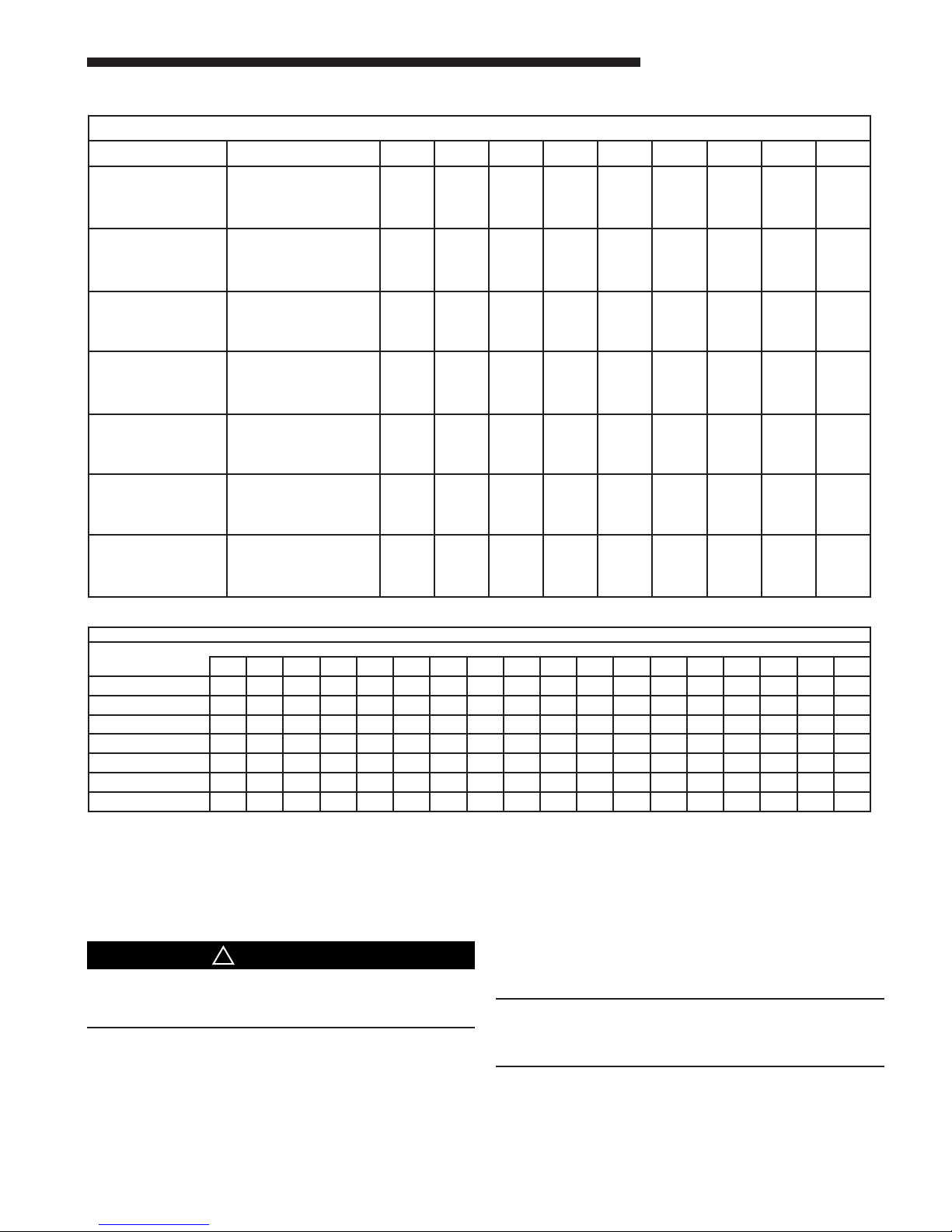
FURNACE AIRFLOW (CFM) VS. STATIC PRESSURE (ins. w.g.)
MODEL SPEED TAP 0.10 0.20 0.30 0.40 0.50 0.60 0.70 0.80 0.90
M801P060AD24AA
M801P060AD36AA
M801P080BD45AA
M801P100CD48AA
M801P100CD60AA
M801P120DD60AA
M801P140DD60AA
4-HIGH - Black
3-MED - HIGH - Blue
2-MED - LOW - Yellow
1-LOW - Red
4-HIGH - Black
3-MED - HIGH - Blue
2-MED - LOW - Yellow
1-LOW - Red
4-HIGH - Black
3-MED - HIGH - Blue
2-MED - LOW - Yellow
1-LOW - Red
4-HIGH - Black
3-MED - HIGH - Blue
2-MED - LOW - Yellow
1-LOW - Red
4-HIGH - Black
3-MED - HIGH - Blue
2-MED - LOW - Yellow
1-LOW - Red
4-HIGH - Black
3-MED - HIGH - Blue
2-MED - LOW - Yellow
1-LOW - Red
4-HIGH - Black
3-MED - HIGH - Blue
2-MED - LOW - Yellow
1-LOW - Red
1200
1025
838
722
1480
1302
1115
956
1798
1384
1210
1005
1965
1645
1407
1202
2165
1962
1705
1492
2241
1981
1721
1476
2377
2115
1806
1527
1155
988
808
689
1429
1276
1100
947
1750
1367
1150
970
1915
1627
1398
1208
2113
1927
1688
1467
2202
1962
1705
1466
2321
2081
1793
1507
1111
951
779
656
1375
1229
1070
918
1692
1333
1108
808
1865
1605
1387
1205
2060
1891
1671
1442
2163
1942
1688
1456
2265
2046
1779
1486
1056
905
742
618
1318
1188
1035
888
1642
1300
1075
775
1805
1575
1375
1195
1995
1839
1636
1414
2106
1904
1671
1440
2199
1992
1738
1473
1001
859
704
579
1282
1141
1000
859
1575
1275
1042
767
1740
1535
1347
1166
1929
1786
1600
1385
2049
1866
1653
1423
2133
1938
1696
1459
924
797
646
528
1100
1088
965
824
1500
1233
1008
733
1670
1482
1318
1140
1842
1724
1547
1346
1979
1805
1611
1392
2050
1872
1655
1422
848
735
588
478
1112
1024
918
788
1425
1192
967
700
1587
1421
1275
1105
1755
1662
1492
1307
1908
1743
1569
1361
1967
1805
1614
1384
774
646
502
376
1029
953
859
741
1325
1142
925
675
1500
1330
1190
1045
1674
1581
1435
1243
1804
1680
1515
1302
1877
1727
1556
1329
701
558
415
275
959
882
790
682
1225
1083
867
617
1370
1220
1095
970
1593
1500
1377
1179
1700
1617
1461
1243
1786
1649
1497
1273
CFM VS. TEMPERATURE RISE
MODEL
M801P060AD24AA
M801P060AD36AA
M801P080BD45AA
M801P100CD48AA
M801P100CD60AA
M801P120DD60AA
M801P140DD60AA
700 800 900 1000 1100 1200 1300 1400 1500 1600 1700 1800 1900 2000 2100 2200 2300 2400
63 56 49 44 40
56 49 44 40 37 34 32
64 57 52 48 44 41
62 57 53 49 46 44 41 39 37
62 57 53 49 46 44 41 39 37 35 34 32 31
AIRFLOW ADJUSTMENT
Check inlet and outlet air temperatures to make sure they
are within the ranges specified on the furnace rating nameplate. If the airflow needs to be increased or decreased, see
the wiring diagram for information on changing the speed
of the blower motor.
Disconnect power to the unit before removing the blower
door. Failure to follow this warning could result in personal injury from moving parts.
This unit is equipped with a blower door switch which cuts
power to the blower and gas valve causing shutdown when
the door is removed. Operation with the door removed or
ajar can permit the escape of dangerous fumes. All panels
must be securely closed at all times for safe operation of the
furnace.
59 56 52 49 47 44 42 40
69 65 61 58 55 52 49 47 45
INDOOR BLOWER TIMING
Heating: The control module controls the indoor blower.
The blower start is fixed at 45 seconds after ignition. The
FAN-OFF period is field selectable by dip switches at 60,
100, 140, or 180 seconds. The factory setting is 100 seconds
(See wiring diagram).
Cooling: The fan delay off period is factory set at 0 seconds. The option for 80 second delay off is field selectable
(See wiring diagram).
NOTE:
Direct drive motors have bearings which are permanently lubricated and under normal use, lubrication is not
recommended.
M801-SF-1C 11
Page 12
Service Facts
▲
WARNING
!
The following warning complies with State of California law, Proposition 65.
This product contains fiberglass wool insulation!
Fiberglass dust and ceramic fibers are believed by the
State of California to cause cancer through inhalation.
Glasswool fibers may also cause respiratory, skin, or
eye irritation.
PRECAUTIONARY MEASURES
●
Avoid breathing fiberglass dust.
●
Use a NIOSH approved dust/mist respirator.
●
Avoid contact with the skin or eyes. Wear long-sleeved,
loose-fitting clothing, gloves, and eye protection.
●
Wash clothes separately from other clothing: rinse
washer thoroughly.
●
Operations such as sawing, blowing, tear-out, and
spraying may generate fiber concentrations requiring
additional respiratory protection. Use the appropriate
NIOSH approved respirator in these situations.
FIRST AID MEASURES
Eye Contact – Flush eyes with water to remove dust.
If symptoms persist, seek medical
attention.
Skin Contact – Wash affected areas gently with soap
and warm water after handling.
CONDITIONS AFFECTING UNIT
PERFORMANCE
1. EXCESSIVE COMBUSTION VENT PRESSURE OR
FLUE BLOCKAGE
If pressure against the induced draft blower outlet
becomes excessive, the pressure switch will shut off the
gas valve until acceptable combustion pressure is again
available.
2. LOSS OF FLAME OR GAS SUPPLY FAILURE
If loss of flame occurs during a heating cycle (when
flame is not present at the sensor), the control module
will retry the ignition sequence up to two times after
the sensor cools. If ignition is not achieved, it will lockout the furnace.
3. POWER FAILURE
If there is a power failure during a heating cycle, the
system will restart the ignition sequence automatically
when power is restored, if the thermostat still calls for
heat.
4. INDUCED DRAFT BLOWER FAILURE
If pressure is not sensed by the pressure switch, it will
not allow the gas valve to open, therefore the unit will
not start. If failure occurs during a running cycle, the
pressure switch will cause the gas valve to close and
shut the unit down.
Fault LED Flash Codes Definitions
INTERGRATED FURNACE CONTROL ERROR FLASH CODES
Flashing Slow --- Normal - No call for Heat
Flashing Fast --- Normal - Call for Heat
Continuous ON --- Replace IFC
Continuous OFF --- Check Power
2 Flashes --- System Lockout (Retries or Recycles exceeded)
3 Flashes --- Pressure Switch Error
4 Flashes --- Open High Limit Device
5 Flashes --- Flame sensed when no flame should be present
6 Flashes --- 115 Volt AC power reversed or Poor Grounding
7 Flashes --- Gas valve circuit error
8 Flashes --- Low flame sense signal
Ingersoll Rand
11819 N. Pennsylvania Street
Carmel, IN 46032
For more information contact
your local dealer (distributor)
The manufacturer has a policy of continuous product and product data improvement and reserves the right to
change design and specifications without notice.
 Loading...