

Ingersoll-Rand M801P080BU48AA, M801P100CU48AA, M801P060AU36AA, M801P140DU60AA, M801P120DU60AA Installer's Manual
...Page 1

18-CD34D1-5-EN
INSTALLER’S GUIDE
Upflow/Horizontal — Downflow/Horizontal, Gas-Fired Furnaces,
“Fan Assisted Combustion System”
M801P040AU24AA
M801P060AU24AA
M801P060AU36AA
M801P080BU36AA
M801P080BU48AA
ALL phases of this installation must comply with
IMPORTANT — This Document is customer property and is to
remain with this unit. Please return to service
information pack upon completion of work.
M801P100BU36AA
M801P100CU48AA
M801P100CU60AA
M801P120DU60AA
M801P140DU60AA
M801P060AD24AA
M801P060AD36AA
M801P080BD45AA
M801P100CD48AA
M801P100CD60AA
M801P120DD60AA
M801P140DD60AA
NATIONAL, STATE AND LOCAL CODES
For VENT SIZING INFORMATION see:
USA —
National Fuel Gas Code ANSI Z223.1/ NFPA 54 (latest version)
CANADA—
Natural Gas Installation Code CAN/ CGA-B149.1 (latest version)
Propane Installation Code CAN/ CGA-B149.2 (latest version)
OPTIONAL ACCESSORIES
Model Number Description
BAYBASE205 Downflow subbase for downflow models
only
BAYFLTR200 External side filter rack
BAYFLTR203 Filter kit horizontal for 17.5" cabinet
BAYFLTR204 Filter kit horizontal for 21" cabinet
BAYFLTR205 Filter kit horizontal for 24.5" cabinet
BAYFLTR317 Cleanable filter for 17.5" cabinet upflow
only
BAYFLTR321 Cleanable filter for 21" cabinet upflow
only
BAYFLTR324 Cleanable filter for 24.5" cabinet upflow
only
BAYLPKT210B Propane conversion kit
BAYLPSS210B LP kit with stainless steel burners
BAYRACK960A Internals filter rack kit for upflow models
BAYVENT800B Masonry chimney vent kit for upflow only
KIT09224 Filter clip kit
BAYBRCKFLT10 Downflow bracket kit
FLR01185 Filter for 14-1/2" cabinet downflow only
FLR01186 Filter for 17-1/2", 21", 24-1/2" cabinet
downflow only
Upflow/ Horizontal* Downflow/ Horizontal*
*Horizontal Conversion for these furnaces may be left
or right side rotation.
A341789P12
Page 2
INSTALLER’S GUIDE
WARNING
SAFETY SECTION
The following safety practices and precautions must be followed
during the installation, servicing, and operation of this furnace.
1. Use only with the type of gas approved for this furnace.
Refer to the furnace rating plate.
2. Install this furnace only in a location and position as
specied in “Location and Clearances” in this document.
3. Provide adequate combustion and ventilation air to the
furnace space as specied in “Air for Combustion and
Ventilation” in this document.
4. Combustion products must be discharged outdoors.
Connect this furnace to an approved vent system only, as
specied in the “Venting” section in this document.
5. Never test for gas leaks with an open ame. Use a
commercially available soap solution made specically
for the detection of leaks to check all connections, as
specied in “Gas Piping” in this document.
6. Always install the furnace to operate within the furnace’s
intended temperature-rise range with a duct system
which has an external static pressure within the allowable
range, as specied on the unit rating plate. Airow with
temperature rise for CFM versus static is shown in this
document.
7. When a furnace is installed so that supply ducts carry
air circulated by the furnace to areas outside the space
containing the furnace, the return air shall also be handled
by a duct(s) sealed to the furnace casing and terminating
outside the space containing the furnace.
8. A gas-red furnace for installation in a residential
garage must be installed as specied in “Location and
Clearances” section in this document.
9. The furnace may be used for temporary heating of
buildings or structures under construction only when the
following conditions have been met:
a. The furnace venting system must be complete and
installed per manufacturer’s instructions.
b. The furnace is controlled only by a room thermostat
(no eld jumpers).
c. The furnace return air duct must be complete and
sealed to the furnace and clean air lters are in place.
d. The furnace input rate and temperature rise must be
veried to be within nameplate marking.
e. 100% of the furnace combustion air requirement must
come from outside the structure.
f. The furnace return air temperature range is between
55 and 80 degrees Fahrenheit.
g. Clean the furnace, duct work, and components upon
substantial completion of the construction process,
and verify furnace operating conditions including
ignition, input rate, temperature rise and venting,
according to the manufacturer’s instructions.
10. This product must be gas piped by a Licensed Plumber
or Gas Fitter in the Commonwealth of Massachusetts.
Safety signal words are used to designate a degree or level of
seriousness associated with a particular hazard. The signal
words for safety markings are WARNING and CAUTION.
b. WARNING indicates a potentially hazardous
situation which, if not avoided, could result in death
or serious injury.
c. CAUTION indicates a potentially hazardous situation
which, if not avoided, may result in minor or moderate
injury. It is also used to alert against unsafe practices
and hazards involving only property damage.
GENERAL INSTALLATION INSTRUCTIONS
The manufacturer assumes no responsibility for equipment
installed in violation of any code or regulation. It is recommended
that Manual J of the Air Conditioning Contractors Association
(ACCA) or A.R.I. 230 be followed in estimating heating
requirements. When estimating heating requirements for
installation at Altitudes above 2000 ft., remember the gas input
must be reduced (See GAS INPUT ADJUSTMENT).
Material in this shipment has been inspected at the factory
and released to the transportation agency without known
damage. Inspect exterior of carton for evidence of rough
handling in shipment. Unpack carefully after moving
equipment to approximate location. If damage to contents
is found, report the damage immediately to the delivering
agency.
Codes and local utility requirements governing the installation of
gas red equipment, wiring, plumbing, and ue connections must
be adhered to. In the absence of local codes, the installation must
conform with latest edition of the National Fuel Gas Code ANSI
Z223.1 • National Installation Code, CAN/CGA B149.1. The
latest code may be obtained from the American Gas Association
Laboratories, 400 N. Capitol St. NW, Washington D.C. 20001,
1-800-699-9277 or www.aga.org
These furnaces have been classied as Fan Assisted Combustion
system CATEGORY I furnaces as required by ANSI Z21.47
“latest edition” and CAN/CGA 2.3. Therefore they do not require
any special provisions for venting other than what is indicated in
these instructions.
!
▲
FIRE OR EXPLOSION HAZARD
Failure to follow the safety warnings exactly could
result in serious injury, death or property damage.
Improper servicing could result in dangerous
operation, serious injury, death, or property
damage.
© 2015 Ingersoll Rand — All Rights Reserved 18-CD34D1-5-EN
Page 3

WARNING
INSTALLER’S GUIDE
!
▲
CARBON MONOXIDE POISONING HAZARD
Failure to follow the steps outlined below for
each appliance connected to the venting system
being placed into operation could result in carbon
monoxide poisoning or death.
The following steps shall be followed for each appliance
connected to the venting system being placed into
operation, while all other appliances connected to the
venting system are not in operation:
Seal any unused openings in the venting
system.
1. Inspect the venting system for proper size and
horizontal pitch, as required in the National Fuel Gas
Code, ANSI Z223.1/NFPA 54 or the CAN/CGA B149
Installation Codes and these instructions. Determine
that there is no blockage or restriction, leakage,
corrosion and other deficiencies which could cause
an unsafe condition.
2. As far as practical, close all building doors and
windows and all doors between the space in which
the appliance(s) connected to the venting system are
located and other deficiencies which could cause an
unsafe condition.
3. Close fireplace dampers.
4. Turn on clothes dryers and any appliance not
connected to the venting system. Turn on any exhaust
fans, such as range hoods and bathroom exhausts,
so they are operating at maximum speed. Do not
operate a summer exhaust fan.
5. Follow the lighting instructions. Place the appliance
be-ing inspected into operation. Adjust the thermostat
so appliance is operating continuously.
6. If improper venting is observed during any of the
above tests, the venting system must be corrected
in accordance with the National Fuel Gas Code,
ANSI Z221.1/NFPA 54 and/or CAN/CGA B149
Installation Codes.
7. After it has been determined that each appliance
connected to the venting system properly vents where
tested as outlined above, return doors, windows,
exhaust fans, fireplace dampers and any other gas
-fired burning appliance to their previous conditions
of use.
Contents
Safety Section ..................................................................2
General Installation Instructions ....................................... 2
Location and Clearances .................................................. 4
Outline Drawings ..............................................................5
Upflow Installation ............................................................7
Downflow Installation ........................................................ 7
Horizontal Installation ....................................................... 7
Air for Combustion and Ventilation .................................... 8
Duct Connections ........................................................... 10
Return Air Filter .............................................................. 11
General Venting Instructions ........................................... 12
Venting into a Masonry Chimney .................................... 13
Field Wiring Diagrams .................................................... 15
Electrical Connections .................................................... 16
Gas Piping ...................................................................... 17
Sequence of Operation ...................................................17
Start-up and Adjustment ................................................. 17
Combustion and Input Check .........................................17
High Altitude Derate .......................................................19
Lighting Instructions ....................................................... 20
Control and Safety Switch Adjustment ...........................20
Operating Information ..................................................... 20
Integrated Furnace Control Error flash Codes ................ 21
Periodic Servicing Requirements ...................................22
Airflow Tables .................................................................. 23
18-CD34D1-5-EN 3
Page 4
INSTALLER’S GUIDE
CAUTION
WARNING
!
▲
To prevent shortening its service life, the furnace
should not be used as a “Construction Heater”
during the finishing phases of construction
until the requirements listed in item 9, a-g of the
safety section of this publication have been met.
Condensate in the presence of chlorides and
fluorides from paint, varnish, stains, adhesives,
cleaning compounds, and cement create a
corrosive condition which may cause rapid
deterioration of the heat exchanger.
!
WARNING
▲
These furnaces are not approved or intended for
installation in manufactured (mobile) housing,
trailers, or recreational vehicles. Failure to follow
this warning could result in property damage,
personal injury, or death.
!
CAUTION
▲
Do NOT install the furnace in a corrosive or
contaminated atmosphere.
!
WARNING
▲
Do NOT install the furnace directly on carpeting,
tile or other combustible material other than
wood flooring. For vertical downflow application,
subbase (BAYBASE205) must be used between
the furnace and combustible flooring. When the
downflow furnace is installed vertically with a
cased coil, a subbase is not required.
!
▲
EXPLOSION HAZARD!
PROPANE GAS IS HEAVIER THAN AIR AND MAY
COLLECT IN ANY LOW AREAS OR CONFINED
SPACES. IN ADDITION, ODORANT FADE MAY
MAKE THE GAS UNDETECTABLE EXCEPT WITH
A WARNING DEVICE. IF THE GAS FURNACE IS
INSTALLED IN A BASEMENT, AN EXCAVATED
AREA OR A CONFINED SPACE, IT IS STRONGLY
RECOMMENDED TO CONTACT A GAS SUPPLIER
TO INSTALL A GAS DETECTING WARNING
DEVICE IN CASE OF A GAS LEAK.
NOTE: The manufacturer of your furnace does not
test any detectors and makes no representations
regarding any brand or type of detector
LOCATION AND CLEARANCES
The location of the furnace is normally selected by the architect,
the builder, or the installer. However, before the furnace is moved
into place, be sure to consider the following requirements:
1. Is the location selected as near the chimney or vent and as
centralized for heat distribution as practical?
2. Do all clearances between the furnace and enclosure
equal or exceed the minimums stated in Clearance Table
on the Outline Drawings.
3. Is there sufcient space for servicing the furnace and other
equipment? A minimum of 24 inches front accessibility
to the furnace must be provided. Any access door or
panel must permit removal of the largest component.
4. Are there at least 3 inches of clearance between the
furnace combustion air openings in the front panel and
any closed panel or door provided?
5. Are the ventilation and combustion air openings large
enough and will they remain unobstructed? If outside
air is used, are the openings set above the highest snow
accumulation level? (See the Air for Combustion and
Ventilation section)
6. Allow sufcient height in supply plenum above the
furnace to provide for cooling coil installation, if the
cooling coil is not installed at the time of this furnace
installation.
7. A furnace shall be installed so electrical components are
protected from water.
8. If the furnace is installed in a residential garage, it must
be installed so that the burners, and the ignition source
are located not less than 18 inches above the oor and the
furnace must be located or protected to avoid physical
damage from vehicles.
4 18-CD34D1-5-EN
Page 5
Ø 1-5/8” HOLE WITH PLUG
INSTALLER’S GUIDE
14-1/2" 9-5/8" 13-1/4" 13"
17-1/2" 9-5/8" 16-1/4" 16"
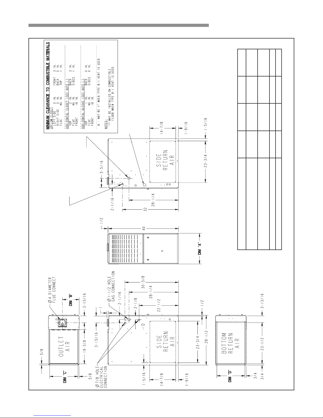
OUTLINE DRAWINGS - UPFLOW/HORIZONTAL
For the M801P Series Furnaces
Ø 7/8” HOLE WITH PLUG
ELECTRICAL CONNECTION
Ø 1-5/8” HOLE WITH PLUG
(ALTERNATE)
MODEL DIM "A" DIM "B" DIM "C" DIM "D"
M801P040AU24AA, M801P060AU24AA
M801P060AU36AA
M801P080BU36AA, M801P080BU48AA
M801P100BU36AA
M801P100CU48AA, M801P100CU60AA 21" 13-1/16" 19-3/4" 19-1/2"
M801P120DU60AA, M801P140DU60AA 24-1/2" 15-5/16" 23-1/4" 23"
18-CD34D1-5-EN 5
Page 6
INSTALLER’S GUIDE
Ø 7/8” HOLE WITH PLUG
ELECTRICAL CONNECTION
(ALTERNATE)
Ø 1-5/8” HOLE WITH PLUG
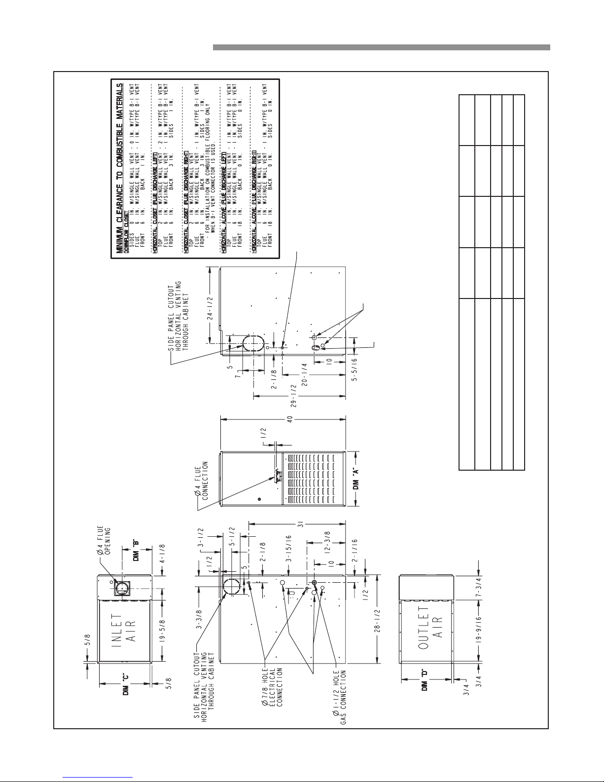
M801P OUTLINE DRAWING - DOWNFLOW\HORIZONTAL
For the M801P Series Furnaces
1-1/2” X 2-1/2” OVAL
GAS CONNECTION
MODEL DIM "A" DIM "B" DIM "C" DIM "D"
M801P060AD24AA, M801P060AD36AA 14-1/2" 9-5/8" 13-1/4" 13"
M801P080BD45AA 17-1/2" 9-5/8" 16-1/4" 16"
M801P100CD48AA, M801P100CD60AA 21" 13-1/16" 19-3/4" 19-1/2"
M801P120DD60AA, M801P140DD60AA 24-1/2" 15-5/16" 23-1/4" 23"
6 18-CD34D1-5-EN
Ø 1-5/8” HOLE
WITH PLUG (3)
Page 7
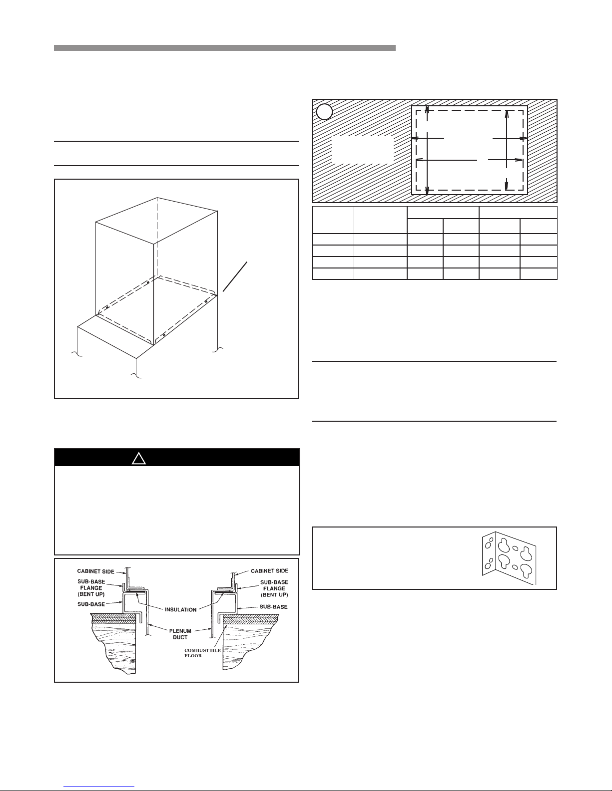
UPFLOW
FURNACE
CASED
COIL
INSTALLER’S GUIDE
UPFLOW INSTALLATION
The coil is always placed downstream of the furnace airow.
Apply gasket material (duct seal eld supplied) to ALL mating
surfaces between the furnace and the coil case.
NOTE: The top flanges on the furnace must be bent
90 degrees upward to allow the coil attachment.
1
Seal with field
supplied sealant
or gasket
Required floor opening: (DOWNFLOW)
Figure 3 and Table 1
3
A (width)
FURNACE
FRONT
CABINET
WIDTH
14-1/2" 13-1/4" 13-5/8" 20-1/8" 12-5/8" 19-3/8"
17-1/2" 16-1/4" 16-5/8" 20-1/8" 15-5/8" 19-3/8"
21" 19-3/4" 20-1/8" 20-1/8" 19-1/8" 19-3/8"
24-1/2" 23-1/4" 23-5/8" 20-1/8" 22-5/8" 19-3/8"
RETURN
DUCT
WIDTH
FLOOR OPENING PLENUM OPENING
B (depth)
D
C
"A" "B" "C" "D"
HORIZONTAL INSTALLATION
The coil and furnace must be fully supported when used in the
horizontal position. Three brackets (with screws) are included
with downow furnaces for installation to stabilize and secure
the furnace and cased coil in the horizontal position. See Figure 4.
VERTICAL
INSTALLATIONS:
DOWNFLOW INSTALLATION
!
WARNING
▲
Do not install the furnace directly on carpeting,
tile or other combustible material other than
wood flooring. For vertical downflow application,
subbase (BAYBASE205) must be used between
the furnace and combustible flooring. When the
downflow furnace is installed vertically with a
cased coil, a subbase is not required.
2
IMPORTANT: The cased coil must be placed
downstream of the furnace. In horizontal
installations, the apex of the coil may point
either toward or away from the furnace. See the
coil Installer's Guide for more details.
The cased coil is secured to the furnace and both the furnace and
the cased coil must be properly supported. The brackets mount
using the rear screws on the coil case and use the screws provided
to secure the bracket to the furnace. The remaining bracket is
placed as close to center as possible (horizontally) between the
coil case front and the furnace bottom channel (for downow/
horizontal furnace). Use four of the screws provided to secure the
bracket. The upow furnace,
4
CASED COIL CONNECTION
BRACKET FOR DOWNFLOW
FURNACE IN HORIZONTAL
DOWNFLOW ONLY
converted to horizontal, aligns and attaches the coil as in Figure 1.
However, the coil requires additional support. This furnace may
be installed in an attic or crawl space in the horizontal position by
placing the furnace on the left or right side (as viewed from the
front in the upright position). The horizontal furnace installation
in an attic should be on a service platform large enough to allow
for proper clearances on all sides and service access to the front
of the furnace (See Clearance Table on Outline Drawings and
Figure 5).
18-CD34D1-5-EN 7
Page 8
INSTALLER’S GUIDE
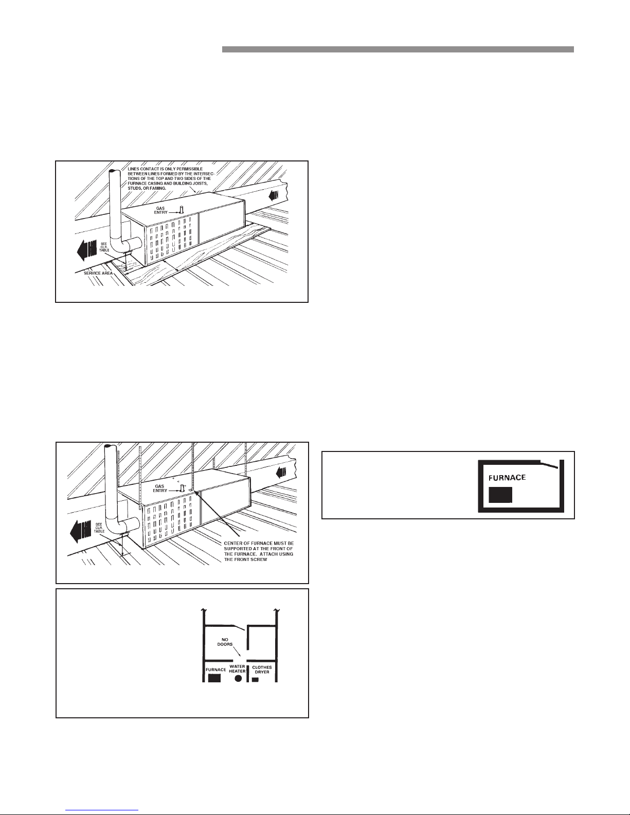
If the furnace is suspended using perforated steel strap (plumber’s
strap), it must be supported at all four corners and in the middle
at the front of the furnace. The forward most screw on the side
of the furnace may be used to connect the strapping (See Figure
6). Line contact is only permissible between lines formed by the
intersection of the top and two sides of the furnace casing and the
building joists, studs, or framing.
5
TYPICAL UPFLOW/HORIZONTAL ATTIC INSTALLATION
A cutout is provided on both sides of the downow furnace
cabinet to allow a 90° elbow to be attached inside the cabinet
and the vent piping to connect there. In horizontal, the downow
furnace may be vented through the top of the cabinet if needed.
In vertical conguration, the downow furnace may be vented
using the side cabinet cutouts. This venting conguration could
be used if an electronic air cleaner is installed.
When the downow furnace is vented through the left side
of the furnace cabinet in horizontal or vertical conguration,
Type B vent pipe must be used within the cabinet.
6
AIR FOR COMBUSTION AND
VENTILATION
Adequate ow of combustion and ventilating air must not be
obstructed from reaching the furnace. Air openings provided in
the furnace casing must be kept free of obstructions which restrict
the ow of air. Airow restrictions affect the efciency and safe
operation of the furnace. Keep this in mind should you choose
to remodel or change the area which contains your furnace.
Furnaces must have a free ow of air for proper performance.
Provisions for combustion and ventilation air shall be made
in accordance with “latest edition” of Section 5.3, Air for
Combustion and Ventilation, of the National Fuel Gas Code,
ANSI Z223.1, or Sections 7.2, 7.3 or 7.4 of CAN/ CGA B149
Installation Codes, and applicable provisions of the local building
codes. Special conditions created by mechanical exhausting of
air and replaces must be considered to avoid unsatisfactory
furnace operation.
Furnace locations may be in “conned space” or “unconned
space”. Unconned space is dened in Table 2 and Figure 7.
These spaces may have adequate air by inltration to provide air
for combustion, ventilation, and dilution of ue gases. Buildings
with tight construction (for example, weather stripping, heavily
insulated, caulked, vapor barrier, etc.), may need additional air
provided as described for conned space.
Conned spaces are installations with less than 50 cu. ft. of space
per 1000 BTU/hr input from all equipment installed. Air for
combustion and ventilation requirements can be supplied from
inside the building as in Figure 9 or from the outdoors, as in
Figure 10.
CONFINED
8
LESS THAN 50 CU.
FT. PER 1000 BTU/
HR. INPUT ALL EQUIP
INSTALLED
Typical Suspended Upow/Horizontal Furnace
7
UNCONFINED
50 CU. FT. OR MORE
PER 1000 BTU/HR.
INPUT ALL EQUIP.
INSTALLED
8 18-CD34D1-5-EN
1. All air from inside the building as in Figure 9: The
conned space shall be provided with two permanent
openings communicating directly with an additional
room(s) of sufcient volume so that the combined volume
of all spaces meets the criteria for an unconned space.
The total input of all gas utilization equipment installed
in the combined space shall be considered in making this
determination. Refer to Table 3, for minimum open areas
required.
2. All air from outdoors as in Figure 10: The conned
space shall be provided with two permanent openings,
one commencing within 12 inches of the top and one
commencing within 12 inches of the bottom of the
enclosure. The openings shall communicate directly, or
by ducts, with the outdoors or spaces (crawl or attic) that
freely communicate with the outdoors. Refer to Table 3,
for minimum open areas required.
Page 9
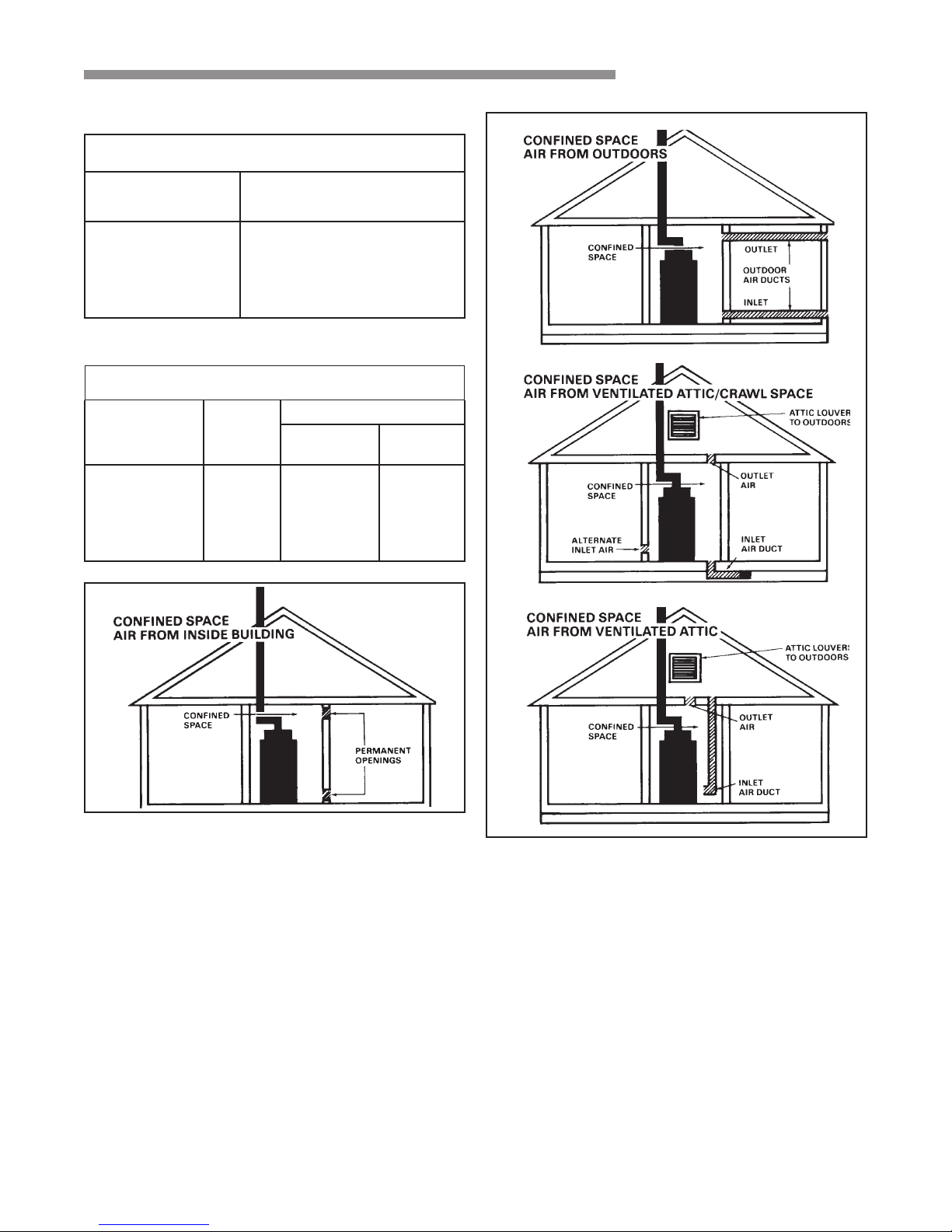
TABLE 2
MINIMUM AREA IN SQUARE FEET FOR
UNCONFINED SPACE INSTALLATIONS
FURNACE MAXIMUM
BTUH / INPUT RAT-
ING
40,000
60,000
80,000
100,000
120,000
140,000
TABLE 3
MINIMUM FREE AREA IN SQUARE INCHES
EACH OPENING (FURNACE ONLY)
Furnace
Maximum
BTUH/INPUT
Rating
40,000
60,000
80,000
100,000
120,000
140,000
WITH 8 FOOT CEILING
MINIMUM AREA IN SQUARE
FEET OF UNCONFINED SPACE
250
375
500
625
750
875
Air From
Inside
100
100
100
100
120
140
Air From Outside
Vertical
Duct
10
15
20
25
30
35
INSTALLER’S GUIDE
0
Horizontal
Duct
20
30
40
50
60
70
9
3. The following types of installations will require use
of OUT DOOR AIR for combustion, due to chemical
exposures:
* Commercial buildings
* Buildings with indoor pools
* Furnaces installed in commercial laundry rooms
* Furnaces installed in hobby or craft rooms
* Furnaces installed near chemical storage areas.
* Exposure to the following substances in the
combustion air supply will also require OUTDOOR
AIR for combustion:
* Permanent wave solutions
* Chlorinated waxes and cleaners
* Chlorine based swimming pool chemicals
* Water softening chemicals
* Deicing salts or chemicals
* Carbon Tetrachloride
* Halogen type refrigerants
* Cleaning solvents (such as perchloroethylene)
* Printing inks, paint removers, varnish, etc.
* Hydrochloric acid
* Cements and glues
* Antistatic fabric softeners for clothes dryers
* Masonry acid washing materials
18-CD34D1-5-EN 9
Page 10
INSTALLER’S GUIDE
DUCT CONNECTIONS
NOTE: The top anges on the furnace must be bent 90 degrees
upward to allow connection to the ducting.
Air duct systems should be installed in accordance with standards
for air conditioning systems, National Fire Protection Association
Pamphlet No. 90. They should be sized in accordance with ACCA
Manual D or whichever is applicable.
Central furnaces, when used in connection with cooling units,
shall be installed in parallel or on the upstream side of the cooling
units to avoid condensation in the heating element, unless
the furnace has been specically approved for downstream
installation. With a parallel ow arrangement, the dampers
or other means used to control ow of air shall be adequate to
prevent chilled air from entering the furnace, and if manually
operated, must be equipped with means to prevent operation of
either unit unless the damper is in full heat or cool position.
On any job, exible connections of nonammable material
may be used for return air and discharge connections to prevent
transmission of vibration. Though these units have been
specically designed for quiet, vibration free operation, air ducts
can act as sounding boards and could, if poorly installed, amplify
the slightest vibration to the annoyance level.
When the furnace is located in a utility room adjacent to the
living area, the system should be carefully designed with returns
which minimize noise transmission through the return air grille.
Although these winter air conditioners are designed with large
blowers operating at moderate speeds, any blower moving a
high volume of air will produce audible noise which could be
objectionable when the unit is located very close to a living area.
It is often advisable to route the return air ducts under the oor
or through the attic. Such design permits the installation of air
return remote from the living area (i.e. central hall).
When the furnace is installed so that the supply ducts carry air
circulated by the furnace to areas outside the space containing the
furnace, the return air shall also be handled by a duct(s) sealed
to the furnace and terminating outside the space containing the
furnace.
Minimum return air/“air entering” temperature for the
furnace is 55° F.
Where there is no complete return duct system, the return
connection must be run full size from the furnace to a location
outside the utility room, basement, attic, or crawl space.
Do not install return air through the back of the furnace
cabinet.
Return Air Duct Connection
All return air duct systems should provide for installation of
return air lters.
NOTE: For Upow 5 ton airow models, if the airow
requirement exceeds 1800 CFM, these models will require
return air openings and lters on both sides; or 1 side and
the bottom; or just the bottom.
1. Set the furnace in place.
2. For side return installations on upow models, remove
the insulation around the opening in the blower
compartment.
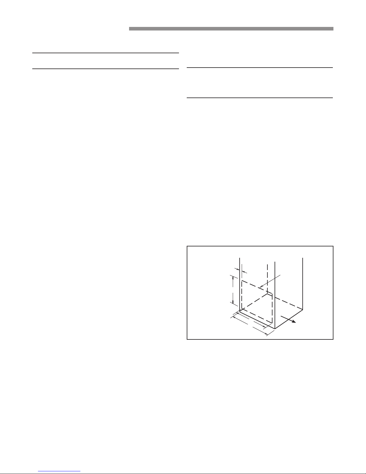
3. The side panels on upow furnaces include locating
notches which may be used as guides for cutting an
opening for return air. Refer to Figure 11 and the outline
drawing in this document for duct connection dimensions
for various furnaces.
4. If a 3/4" ange is to be used for attaching the air inlet duct,
add to cut where indicated by solid lines in Figure 11. Cut
corners diagonally and bend outward to form ange.
5. If anges are not required, and a lter frame is installed,
cut along knockout guidelines.
6. Upow Furnaces: Filter brackets are available for
lter use within the furnace cabints. Order RTR00133
and CLP00359. If bottom return opening is not used,
fabricate and install a sheet metal plate in the bottom of
the furnace cabinet
q
LOCATING
NOTCHES
PROVIDED
FOR SIDE
UPFLOW FURNACE ONLY
CUT
*
OUT
FOR
*
SIDE
FILTER
RETURN
CUTOUT
FURNACE
*SEE OUTLINE
*
*
FRONT
DRAWING
Downow Furnaces: Brackets must be eld supplied. Order
BAYBRCKFLT10. Also 2 FLR01185 for 14.5" models, or
2 FLR01186 for 17.5", 21.0" and 24.5" models must be
ordered.
When the upow furnace is installed in the horizontal right
or left application and a return duct is attached to the top
side as shown in Figure 12, the lter must be installed in a
remote location.
Do not install the lter in the return duct directly above the
furnace in horizontal applications.
10 18-CD34D1-5-EN
Page 11

WARNING
WARNING
INSTALLER’S GUIDE
!
▲
Do NOT install the filter in the return duct directly
above the furnace in horizontal applications. Install
the filter remotely. Installing the filter directly
above the furnace in horizontal applications may
cause property damage, serious injury or death.
!
▲
TO PREVENT INJURY OR DEATH DUE TO CONTACT
WITH MOVING PARTS, TURN THE POWER TO THE
FURNACE OFF BEFORE SERVICING FILTERS.
When the upow furnace is installed in the horizontal right
or left application and a close coupled (less than 36") return
duct is attached to the bottom side of the furnace as shown
in Figure 12, securely attach a 1/2" mesh metal hardware
cloth protective screen to the inside bottom of the lter grill
to prevent personal injury from contacting moving parts
when reaching into the return opening to replace the
lter.
REMOVE FILTER FROM UPFLOW
FURNACE WHEN RETURN DUCT IS
ATTACHED TO FURNACE TOP SIDE
(HORIZONTAL LEFT OR RIGHT APPLICATIONS) AS SHOWN.
Close coupled (less than 36")
return (filter directly beneath bottom
side return) not recommended due to
noise considerations. If used, securely
attach 1/2" mesh metal hardware cloth
protective screen to the inside bottom of
filter grill.
FILTER
w
RETURN AIR FILTER
These furnaces require high velocity type air lters which may
be located within the furnace blower compartment for UPFLOW
furnaces in either a BOTTOM or SIDE (left side or right side)
return air inlet. See Figures 13 and 14. Some lters may need to
be trimmed for side or bottom lter use.
NOTE: On upow 5 ton airow models, if the airow
requirement exceeds 1800 CFM, these models will require
return air openings and lters on both sides; OR 1 side and
the bottom; OR just the bottom.
NOTE: Upow models only - Installation of the alternate
bottom lter kit requires the bottom ange to be bent at.
Optional downow furnace lters must be located outside the
furnace cabinet. Typical installations are shown in Figures 14 and
15. Tables 5 and 6 provide information for installation of the lter
retaining brackets shipped with downow furnaces.
TABLE 4
MODEL CABINET WIDTH
M801P040AU24AA
M801P060AU24AA
M801P060AU36AA
M801P080BU36AA
M801P080BU48AA
M801P100BU36AA
M801P100CU48AA
M801P100CU60AA
M801P120DU60AA
M801P140DU60AA
M801P060AD24AA
M801P060AD36AA
M801P080BD45AA 17-1/2"
M801P100CD48AA
M801P100CD60AA
M801P120DD60AA
M801P140DD60AA
14-1/2" 1 - 14 X 25 X 1
17-1/2" 1 - 17 X 25 X 1
21" 1 - 20 X 25 X 1
24-1/2" 1 - 24 X 20 X 1
14-1/2"
21"
24-1/2"
REQUIRED FILTER
SIZE FOR BOTTOM
BAYBRCKFLT10
2 - FLR01185
BAYBRCKFLT10
2 - FLR01186
BAYBRCKFLT10
2 - FLR01186
BAYBRCKFLT10
2 - FLR01186
Close coupled (less than 36") return (lter directly beneath
bottom side return) is not recommended due to noise
considerations.
7. Connect the duct work to the furnace. See Outline
Drawing for supply and return duct size and location.
Flexible duct connectors are recommended to connect
both supply and return air ducts to the furnace.
If only the front of the furnace is accessible, it is recommended
that both supply and return air plenums are removable.
8. When replacing a furnace, old duct work should be
cleaned out. Thin cloths should be placed over the
registers and the furnace fan should be run for 10 minutes.
Don’t forget to remove the cloths before you start the
furnace.
18-CD34D1-5-EN 11
e
BAYBRCKFLT10
Airflow
Typical Filters of Upflow in Horizontal
Page 12
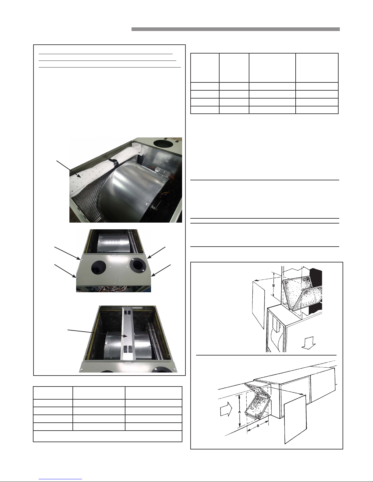
INSTALLER’S GUIDE
Important: When using the supplied high velocity
filters, the filter support base must be installed into
the furnace duct flange prior to ductwork installation.
Remove the brackets from the blower compartment. They are
wrapped in foam and taped to the side of the downflow unit.
Remove the four screws securing the top panel. Save screws.
Slide the top panel forward approximately 1”.
With support tabs facing up, install the filter base by inserting
one end tab into the duct flange at the rear of the furnace.
Slide the top panel back to its original position, engaging the
other end tab in the slot. Replace screws.
Remove
brackets
TABLE 6
CABINET
WIDTH
14-1/2" 13-1/4" 12" 14"
17-1/2" 16-1/4" 15" 14"
21" 19-3/4" 19-1/2" 14"
24-1/2" 23-1/4" 22" 14"
RETURN
DUCT
WIDTH
FILTER ACCESS
OPENING -
DIMENSION "A"
FILTER
ACCESS
OPENING -
DIMENSION
"B"
GENERAL VENTING INSTRUCTIONS
VENT PIPING
These furnaces have been classied as Fan-Assisted Combustion
System, Category I furnaces under the “latest edition” provisions
of ANSI Z21.47 and CAN/CGA 2.3 standards. Category I
furnaces operate with a non-positive vent static pressure and with
a ue loss of not less than 17 percent.
NOTE: If desired, a side wall termination can be accomplished
through the use of an “add-on” draft inducer. The inducer
must be installed according to the inducer manufacturer’s
instructions. Set the barometric pressure relief to achieve
-0.02 inch water column.
Screw
locations
Flanges
upward
TABLE 5
CABINET
WIDTH
14-1/2" 2 - 14X20X1 12-7/8"
17-1/2" 2 - 16X20X1 14-3/8"
21" 2 - 16X20X1 13-1/8"
24-1/2" 2 - 16X20X1 11-5/8"
* Location dimension is from end of duct to the screw holes for the
FILTER
SIZE
bracket.
FILTER BRACKET
LOCATION *
NOTE: When the downow furnace is vented through the
left side of the furnace cabinet using the provided cutout,
Type B vent piping must be used.
DOWNFLOW
r
Airflow
DOWNFLOW/
HORIZONTAL
Airflow
t
12 18-CD34D1-5-EN
Page 13
WARNING
WARNING
WARNING
INSTALLER’S GUIDE
!
▲
CARBON MONOXIDE POISONING HAZARD
Failure to follow the steps outlined below for
each appliance connected to the venting system
being placed into operation could result in carbon
monoxide poisoning or death.
The following steps shall be followed for each appliance
connected to the venting system being placed into
operation, while all other appliances connected to the
venting system are not in operation:
1. Seal any unused openings in the venting system.
2. Inspect the venting system for proper size and
horizontal pitch, as required in the National Fuel Gas
Code, ANSI Z223.1/NFPA 54 or the CAN/CGA B149
Installation Codes and these instructions. Determine
that there is no blockage or restriction, leakage,
corrosion and other deficiencies which could cause
an unsafe condition.
3. As far as practical, close all building doors and
windows and all doors between the space in which
the appliance(s) connected to the venting system are
located and other spaces of the building.
4. Close fireplace dampers.
5. Turn on clothes dryers and any appliance not
connected to the venting system. Turn on any exhaust
fans, such as range hoods and bathroom exhausts,
so they are operating at maximum speed. Do not
operate a summer exhaust fan.
6. Follow the lighting instructions. Place the appliance
being inspected into operation. Adjust the thermostat
so appliance is operating continuously.
7. If improper venting is observed during any of the
above tests, the venting system must be corrected
in accordance with the National Fuel Gas Code,
ANSI Z221.1/NFPA 54 and/or CAN/CGA B149
Installation Codes.
8. After it has been determined that each appliance
connected to the venting system properly vents where
tested as outlined above, return doors, windows,
exhaust fans, fireplace dampers and any other gasfired burning appliance to their previous conditions of
use.
The furnace shall be connected to a factory built chimney or
vent complying with a recognized standard, or a masonry or
concrete chimney lined with a lining material acceptable to
the authority having jurisdiction.
!
WARNING
▲
Furnace venting into an unlined masonry chimney
or concrete chimney is prohibited.
Failure to follow this warning could result in
property damage, personal injury, or death.
VENTING INTO A MASONRY CHIMNEY
If the chimney is oversized, the liner is inadequate, or ue-
gas condensation is a problem in your area, consider using the
chimney as a pathway or chase for type “B” vent or exible vent
liner. If exible liner material is used, size the vent using the “B”
vent tables, then reduce the maximum capacity by 20% (multiply
0.80 times the maximum capacity).
Internal Masonry Chimneys
Venting of fan assisted appliances into a lined, internal masonry
chimney is allowed only if it is common vented with at least one
natural draft appliance; OR, if the chimney is lined with type “B”,
double wall vent or suitable exible liner material (See Table 7).
!
▲
The chimney liner must be thoroughly inspected
to insure no cracks or other potential areas for
flue gas leaks are present in the liner. Liner leaks
will result in early deterioration of the chimney.
Failure to follow this warning could result in
carbon monoxide poisoning or death.
TABLE 7
MASONRY CHIMNEY VENTING
Tile Lined Chimney Chimney Lining
Type Furnace Internal External “B” Vent
Single Fan
Assist
Fan Assist
+ Fan Assist
Fan Assist
+ Natural
* Flexible chimney liner size is determined by using the type “B” vent size
for the available BTUH input, then reducing the maximum capacity by 20%
(multiply maximum capacity times 0.80). The minimum capacity is the same
as shown in the “B” vent tables.
No No Ye s Yes*
No No Ye s Yes*
Ye s No Ye s Yes*
External Masonry Chimney
!
▲
CARBON MONOXIDE POISONING HAZARD
This masonry chimney kit shall NOT be installed
on any furnaces with 40,000 BTU/H inputs or any
downflow models. Failure to follow this warning
could result in carbon monoxide poisoning,
personal injury, or death.
NOTE: Masonry Chimney Kit BAYVENT800B may be used
with these furnaces (Upow model furnaces 60,000 BTU/H
and above only) to allow venting into an external masonry
chimney. Refer to BAYVENT800B Installer's Guide for
application requirements. The following section does not
apply if BAYVENT800B (Masonry Chimney Kit) is used. All
instructions with the kit must be followed.
Flexible
Metal Liner
18-CD34D1-5-EN 13
Page 14
INSTALLER’S GUIDE
WARNING
Venting of fan assisted appliances into external chimneys (one
or more walls exposed to outdoor temperatures), requires the
chimney be lined with type “B”, double wall vent or suitable
exible chimney liner material. This applies in all combinations
of common venting as well as for fan assisted appliances vented
alone.
The following installation practices are recommended to
minimize corrosion caused by condensation of ue products in
the furnace and ue gas system.
!
▲
CARBON MONOXIDE POISONING HAZARD
Failure to follow the installation instructions for
the venting system being placed into operation
could result in carbon monoxide poisoning or
death.
1. Avoid an excessive number of bends.
2. Horizontal runs should pitch upward at least 1/4" per
foot.
3. Horizontal runs should be as short as possible.
4. All vent pipe or connectors should be securely supported
and must be inserted into, but not beyond the inside wall
at the chimney vent.
5. When vent connections must pass through walls or
partitions of combustible material, a thimble must be
used and installed according to local codes.
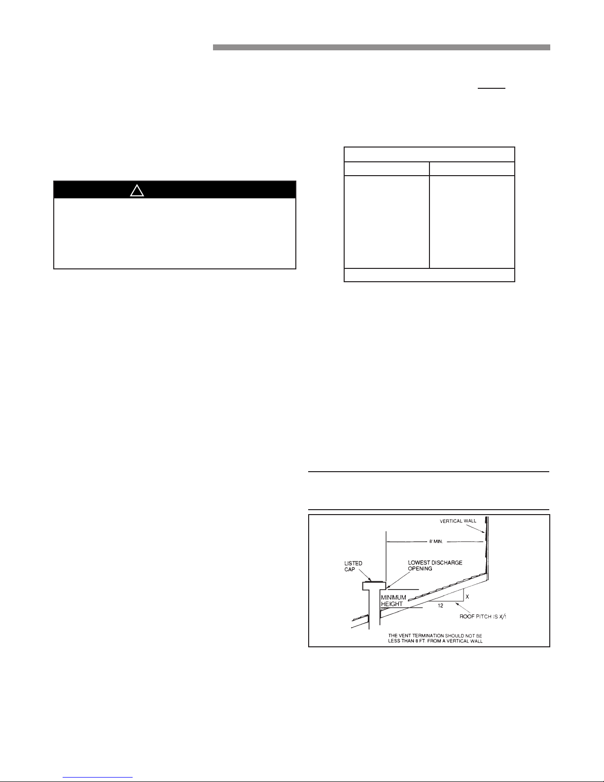
6. Vent pipe through the roof should be extended to a height
determined by National Fuel Gas Code or local codes.
It should be capped properly to prevent rain water from
entering the vent. Roof exit should be waterproofed.
7. Use type “B” double wall vent when vent pipe is routed
through cool spaces (below 60° F.).
8. Where long periods of airow are desired for comfort,
use long fan cycles instead of continuous airow.
9. Apply other good venting practices as stated in the venting
section of the National Fuel Gas Code ANSI Z223.1
“latest edition”.
10. Vent connectors serving appliance vented by natural draft
or non-positive pressure shall not be connected into any
portion of a mechanized draft system operating under
positive pressure.
11. Horizontal pipe runs must be supported by hangers,
straps or other suitable material in intervals at a minimum
of every 3 feet of pipe.
12. A furnace shall not be connected to a chimney or ue
serving a separate appliance designed to burn solid fuel.
13. The ow area of the largest section of vertical vent or
chimney shall not exceed 7 times the smallest listed
appliance categorized vent area, ue collar area, or draft
hood outlet area unless designed in accordance with
approved engineering methods.
Maximum Vent or Tile
= X 7
Lined Chimney Flow Area
*Drafthood outlet diameter, ue collar diameter, or listed appliance categorized vent diameter.
π(D*)
4
2
TABLE 8
GAS VENT TERMINATION
ROOF PITCH MINIMUM HEIGHT
FLAT TO 7/12
OVER 7/12 TO 8/12
OVER 8/12 TO 9/12
OVER 9/12 TO 10/12
OVER 10/12 TO 11/12
OVER 11/12 TO 12/12
OVER 12/12 TO 14/12
OVER 14/12 TO 16/12
OVER 16/12 TO 18/12
OVER 18/12 TO 20/12
OVER 20/12 TO 22/12
* THIS REQUIREMENT COVERS MOST INSTALLATIONS
1.0 FEET *
1.5 FEET
2.0 FEET
2.5 FEET
3.25 FEET
4.0 FEET
5.0 FEET
6.0 FEET
7.0 FEET
7.5 FEET
8.0 FEET
Carbon monoxide, re or smoke can cause serious bodily injury,
death, and/ or property damage.
A variety of potential sources of carbon monoxide can be found
in a building or dwelling such as gas-red clothes dryers, gas
cooking stoves, water heaters, furnaces and replaces. The U.S.
Consumer Product Safety Commission recommends that users of
gas-burning appliances install carbon monoxide detectors as well
as re and smoke detectors per the manufacturer’s installation
instructions to help alert dwelling occupants of the presence of
re, smoke or unsafe levels of carbon monoxide. These devices
should be listed by Underwriters Laboratories, Inc. Standards
for Single and Multiple Station Carbon Monoxide Alarms,
UL 2034 or CSA International Standard, Residential Carbon
Monoxide Alarming Devices, CSA 6.19.
NOTE: The manufacturer of your furnace does not test any
detectors and makes no representations regarding any brand
or type of detector.
y
14 18-CD34D1-5-EN
Page 15
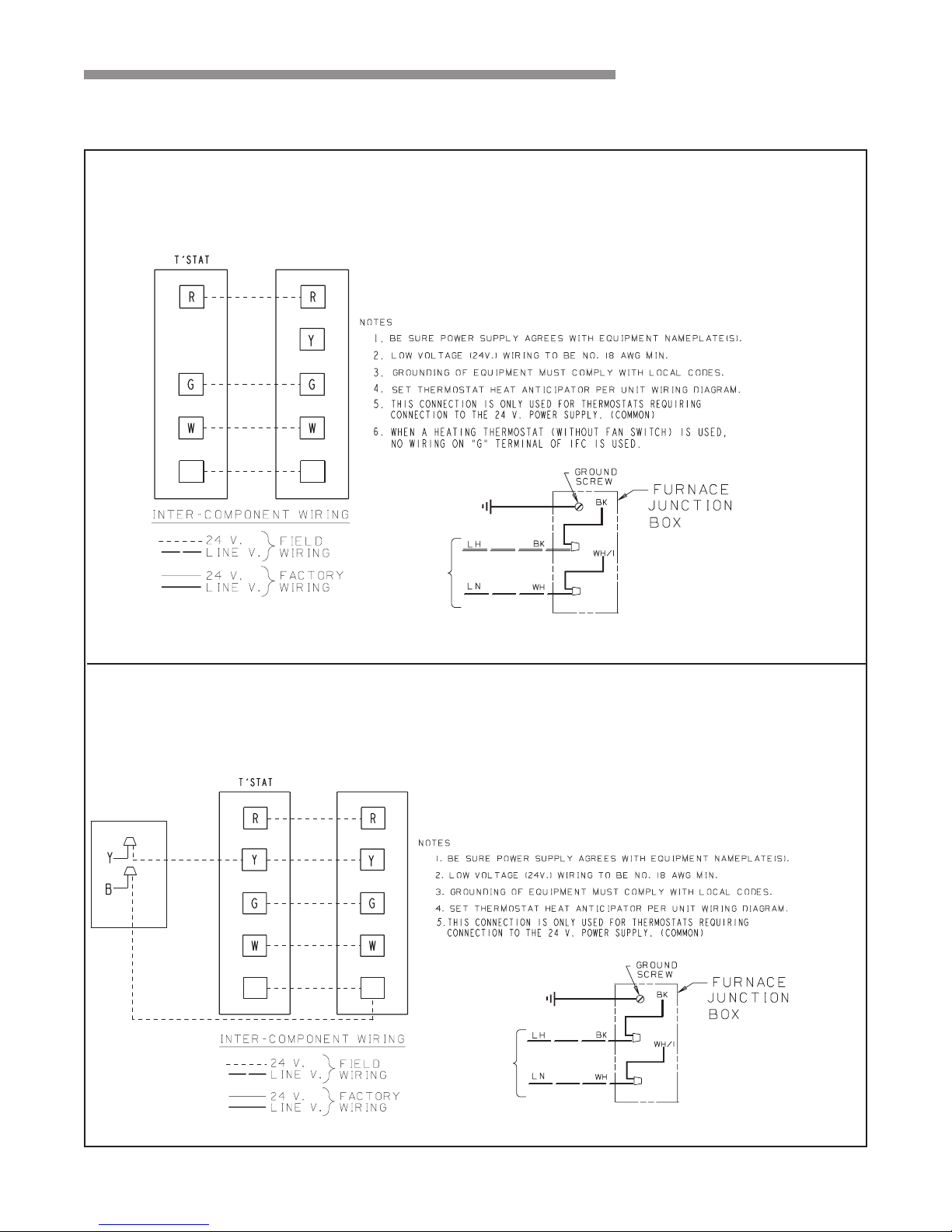
OUTDOOR UNIT
(NO TRANSFORMER)
SEE
NOTE 5
From drawing B342023 Rv 0
FURNACE
B/C
B/C
TO 115 V 1 PH.,
60 HZ., POWER
SUPPLY PER
LOCAL CODES
FIELD WIRING DIAGRAM FOR 1 STAGE FURNACE
1 STAGE HEATING, 1 STAGE COOLING
USING A 1 STAGE HEATING, 1 STAGE COOLING THERMOSTAT
(OUTDOOR SECTION WITHOUT TRANSFORMER)
SEE
NOTE 5
From drawing B342026 Rv 0
FURNACE
SEE
NOTE 6
B/C
B/C
TO 115 V 1 PH.,
60 HZ., POWER
SUPPLY PER
LOCAL CODES
FIELD WIRING DIAGRAM FOR 1 STAGE FURNACE
1 STAGE HEATING
USING A 1 STAGE HEATING THERMOSTAT
NO COOLING
FIELD WIRING DIAGRAMS
INSTALLER’S GUIDE
18-CD34D1-5-EN 15
Page 16
INSTALLER’S GUIDE
WARNING
CAUTION
WARNING
WARNING
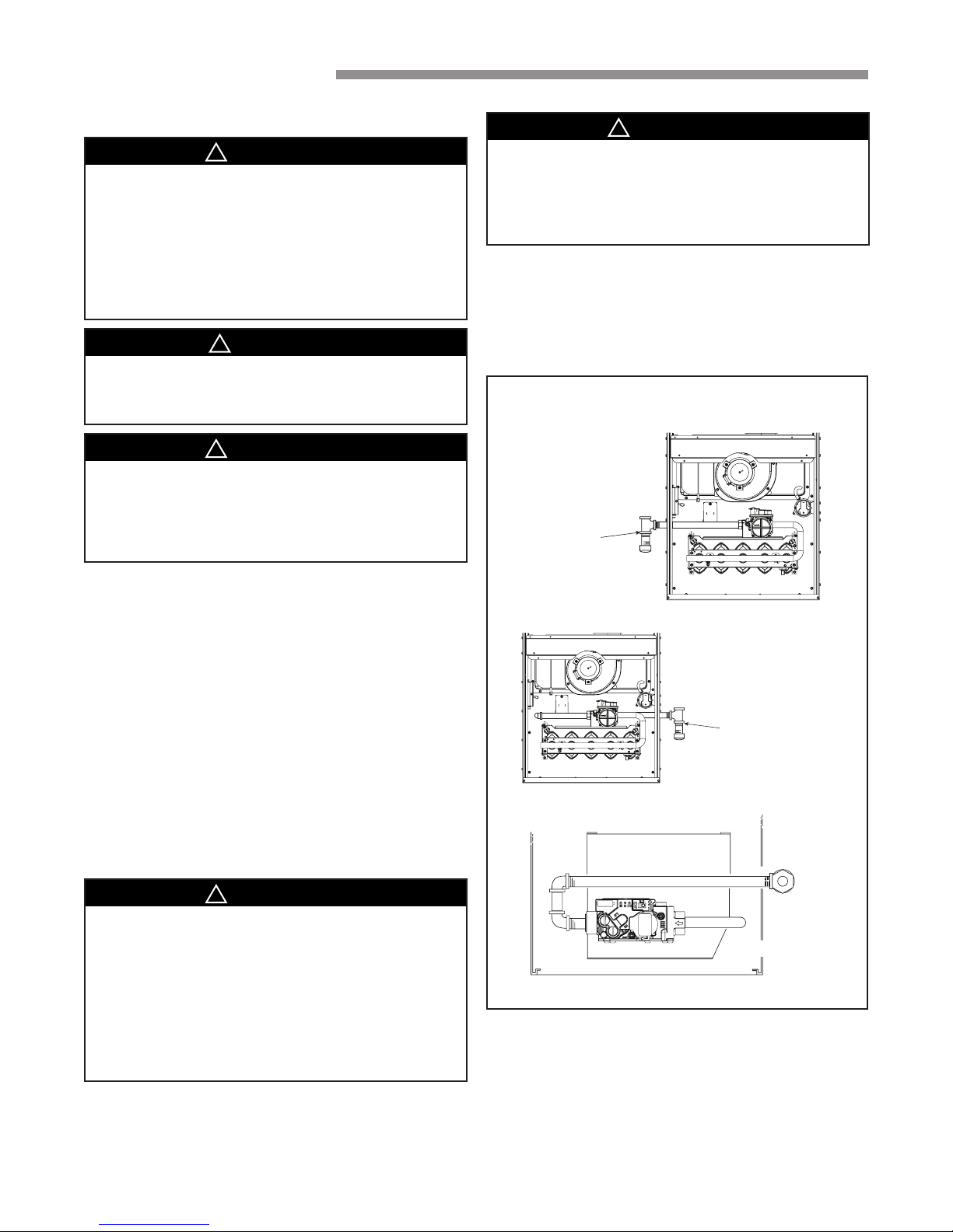
DRIP LEG
TOP VIEW
AUTOMATIC GAS VALVE
WITH MANUAL SHUTOFF
DRIP LEG
ELECTRICAL CONNECTIONS
!
▲
The cabinet must have an uninterrupted or
unbroken ground according to National Electrical
Code, ANSI/NFPA 70 - “latest edition” and
Canadian Electrical Code, CSA C22.1 or local
codes to minimize personal injury if an electrical
fault should occur. Failure to follow this warning
could result in an electrical shock, fire, injury, or
death.
!
▲
The integrated furnace control is polarity
sensitive. The hot leg of the 115 VAC power must
be connected to the BLACK field lead.
!
▲
To prevent injury or death due to electrical shock
or contact with moving parts, lock unit disconnect
switch in the open position before servicing the
unit. Failure to follow this warning could result in
electrical shock, personal injury, or death.
!
▲
TO PREVENT AN EXPLOSION OR POSSIBLE
INJURY, DEATH AND EQUIPMENT DAMAGE,
DO NOT STORE COMBUSTIBLE MATERIALS,
GASOLINE OR OTHER FLAMMABLE VAPORS OR
LIQUIDS NEAR THE UNIT.
IMPORTANT:
A sediment trap must be installed in the gas line
before the furnace gas valve. The sediment trap
must be located as close to the furnace cabinet
as practical.
u
LEFT SIDE PIPING (STANDARD)
Make wiring connections to the unit as indicated on enclosed
wiring diagram. As with all gas appliances using electrical
power, this furnace shall be connected into a permanently live
electric circuit. It is recommended that it be provided with a
separate “circuit protection device” electric circuit. The furnace
must be electrically grounded in accordance with local codes or
in the absence of local codes with the National Electrical Code,
ANSI/ NFPA 70 “latest edition” or Canadian Electrical Code,
CSA C22.1, if an external electrical source is utilized.
All eld supplied wiring must conform with the temperature
limitation for Type T wire [63° F (35° C)], when installed in
accordance with these instructions and wiring diagrams supplied
with the furnace. A disconnecting means must be located within
sight from, and readily accessible to, the furnace. Refer to the
SERVICE FACTS literature for unit wiring diagrams in addition
to the diagram inside the blower door.
!
WARNING
▲
FIRE OR EXPLOSION HAZARD
Failure to follow the safety warnings exactly could
result in serious injury, death or property damage.
Never test for gas leaks with an open flame. Use
a commercially available soap solution made
specifically for the detection of leaks to check
all connections. A fire or explosion may result
causing property damage, personal injury, or loss
of life.
RIGHT SIDE PIPING (OPTIONAL)
TOP VIEW OF RIGHT SIDE PIPING
16 18-CD34D1-5-EN
Page 17
WARNING
WARNING
WARNING
INSTALLER’S GUIDE
GAS PIPING
!
▲
FIRE - EXPLOSION HAZARD
DO NOT RUN FLEXIBLE GAS LINE THROUGH THE
FURNACE CABINET WALL. FAILURE TO FOLLOW
THIS WARNING COULD RESULT IN PROPERTY
DAMAGE, SERIOUS PERSONAL INJURY, OR DEATH.
This unit is shipped standard for left side installation of gas
piping. A piping cutout is also provided in the right side for an
alternate piping arrangement. The installation of piping shall
be in accordance with piping codes and the regulations of the
local gas company. Pipe joint compound must be resistant to the
chemical reaction with liqueed petroleum gases. Refer to piping
Table 9 for delivery sizes.
NOTE: Refer to local codes and the National Fuel Gas Code,
current edition, for gas pipe requirements.
The furnace and its individual shut-off valve must be disconnected
from the gas supply piping system during any pressure testing of
that system at test pressures in excess of 1/2 psig.
The furnace must be isolated from the gas supply piping by
closing its individual manual shut-off valve during any pressure
testing of the gas supply piping system at test pressures equal to
or less than 1/2 psig.
!
CAUTION
▲
that the pressure switch contacts are open and the limit switch(es)
contacts are closed, the draft blower will be energized.
As the induced draft blower comes up to speed, the pressure
switch contacts will close and the ignitor warm up period will
begin. The ignitor will heat for approx. 17 seconds, then the gas
valve is energized to permit gas ow to the burners. The ame
sensor conrms that ignition has been achieved within the 6
second ignition trial period.
After the ame sensor conrms that ignition has been achieved,
the delay fan ON period (xed at 45 seconds) begins timing.
After the delay of 45 seconds, the indoor blower motor will be
energized and will continue to run during the heating cycle.
When the thermostat is satised, R and W thermostat contacts
open, the gas valve will close, the ames will extinguish, and the
induced draft blower will be de-energized. The indoor blower
motor will continue to run for the fan off period (xed at 100
seconds), then will be de-energized by the control module.
!
▲
FIRE OR EXPLOSION HAZARD
Failure to follow the safety warnings exactly could
result in serious injury, death or property damage.
Never test for gas leaks with an open flame. Use a
commercially available soap solution made specifically
for the detection of leaks to check all connections. A
fire or explosion may result causing property damage,
personal injury, or loss of life
Use a backup wrench on the gas valve when
installing gas piping to prevent damage to the gas
valve and manifold assembly.
NOTE: Maximum pressure to the gas valve for natural gas
is 13.8" W.C. Minimum pressure is 5.0" W.C. Maximum
pressure to the gas valve for propane is 13.8" W.C. Minimum
pressure is 11.0" W.C.
All gas ttings must be checked for leaks using a soapy
solution before lighting the furnace.
DO NOT CHECK WITH AN OPEN FLAME!
The following warning complies with the State of California law, Proposition 65.
!
▲
HAZARDOUS GASES!
EXPOSURE TO FUEL SUBSTANCES OR BY
PRODUCTS OF INCOMPLETE FUEL COMBUSTION
IS BELIEVED BY THE STATE OF CALIFORNIA TO
CAUSE CANCER, BIRTH DEFECTS, OR OTHER
REPRODUCTIVE HARM.
SEQUENCE OF OPERATION
Thermostat call for heat
R and W thermostat contacts close signaling the control module
to run its self-check routine. After the control module has veried
START-UP AND ADJUSTMENT
Preliminary Inspections
With gas and electrical power “OFF”
1. Duct connections are properly sealed
2. Filters are in place
3. Venting is properly assembled
4. Blower door is in place
Turn knob on main gas valve within the unit to the “OFF”
position. Turn the external gas valve to “ON”. Purge the air from
the gas lines. After purging, check all gas connections for leaks
with a soapy solution – DO NOT CHECK WITH AN OPEN
FLAME. Allow 5 minutes for any gas that might have escaped
to dissipate. LP Gas, being heavier than air, may require forced
ventilation. Turn the knob on the gas valve in the unit to the
“ON” position.
COMBUSTION AND INPUT CHECK
1. Make sure all gas appliances are off except furnace.
2. Clock the gas meter with the furnace operating (determine
the dial rating of the meter) for one revolution.
3. Match the “Sec” column in the gas ow (in cfh) Table 12
with the time clocked.
4. Read “Flow” column opposite number of seconds
clocked.
18-CD34D1-5-EN 17
Page 18
INSTALLER’S GUIDE
CAUTION
5. Use the following factors if necessary:
For 1 Cu. Ft. Dial Gas Flow CFH = Chart Flow Reading ÷ 2
For 1/2 Cu Ft. Dial Gas Flow CFH = Chart Flow Reading ÷ 4
For 5 Cu. Ft. Dial Gas Flow CFH = 10X Chart Flow Reading ÷ 4
6. Multiply the nal gure by the heating value of the gas
obtained from the utility company and compare to the
nameplate rating. This must not exceed the nameplate
rating.
Gas Valve Adjustment
Changes can be made by adjusting the manifold pressure (See
Table 14), or changing orices (orice change may not always be
required). To adjust the manifold pressure:
1. Turn off all electrical power to the system.
2. Attach a manifold pressure gauge with exible tubing
to the outlet pressure boss marked “OUT P” on WhiteRodgers gas valve model 36J. See Figure 18 for WhiteRodgers gas valve model 36J.
3. Loosen (Do Not remove) the pressure tap test set screw
one turn with 3/32" hex wrench.
a. The pressure tap adjustment kit (KIT07611) contains
a 3/32" hex wrence, a 5/16" hose and a connector and
can be ordered through Global Parts.
4. Turn on system power and energize valve.
5. Adjust gas heat by removing adjustment regulator cover
screw.
a. To increase outlet pressure, turn regulator adjust
screw clockwise.
b. To decrease outlet pressure, turn the regulator adjust
screw counterclockwise.
c. Adjust regulator until pressure shown on mano meter
matches pressure specied in Table 14.
d. The input of no more than nameplate rating and no
less than 93% of the nameplate rating, unless the unit
is derated for high altitude.
e. Replace and tighten regulator cover screw securely.
6. Cycle valve several times to verify regulator setting.
a. Repeat steps 5-6 if needed.
7. Turn off all electrical power to the system.
8. Remove the manometer and exible tubing and tighten
the pressure tap screw.
9. Using a leak detection solution or soap suds, check for
leaks at the pressure outlet boss and pressure tap test
screw.
10. Turn on system power and check operation of unit.
!
▲
Replace and/ or tighten all plugs removed or
loosened when adjusting gas pressure. Leak
check the fittings before placing the furnace into
regular service. Failure to follow this warning
could result in fire, explosion, or property damage.
For LP gases, the nal manifold pressure setting shall be 10.5"
W.C. with an input of no more than the nameplate rating and no
less than 93% of the nameplate rating, unless the unit is derated
for altitude. Table 10 lists the main burner orices shipped with
the furnace. If a change of orices is required to correct the input
rate, refer to Table 11.
Input ratings (BTUH) of these furnaces are based on sea level
operation and should not be changed at elevations up to 2,000 ft.
If the installation is 2,000 ft. or above, the furnace input rate
(BTUH) shall be reduced 4% for each 1,000 ft. above sea level.
The furnace input rate shall be checked by clocking the gas
ow rate (CFH) and multiplying by the heating value obtained
from the local utility supplier for the gas being delivered at the
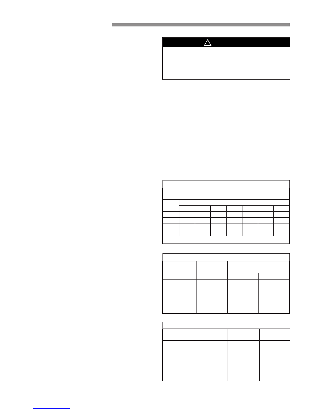
TABLE 9
NATURAL GAS ONLY
TABLE OF CUBIC FEET PER HOUR OF GAS
FOR VARIOUS PIPE SIZES AND LENGTHS
PIPE
SIZE
1/2 132 92 73 63 56 50 46
3/4 278 190 152 130 115 105 96
1-1/4 1050 730 590 520 440 400 370
This table is based on pressure drop of 0.3 inch W.C. and 0.6 SP.GR. gas
10 20 30 40 50 60 70
1 520 350 285 245 215 195 180
LENGTH OF PIPE
TABLE 10
ORIFICE SIZES
INPUT
RATING
BTUH
40,000
60,000
80,000
100,000
120,000
140,000
NUMBER
OF
BURNERS
2
3
4
5
6
7
MAIN BURNER ORIFICE
DRILL SIZE
NAT. GAS LP GAS
45
45
45
45
45
45
56
56
56
56
56
56
TABLE 11
PART NUMBERS FOR REPLACEMENT ORIFICES
DRILL
SIZE
44
45
46
47
48
49
50
PART
NUMBER
ORF00501
ORF00644
ORF00909
ORF00910
ORF01099
ORF00503
ORF00493
DRILL
SIZE
54
55
56
57
58
59
PART
NUMBER
ORF00555
ORF00693
ORF00907
ORF00908
ORF01338
ORF01339
18 18-CD34D1-5-EN
Page 19
INSTALLER’S GUIDE
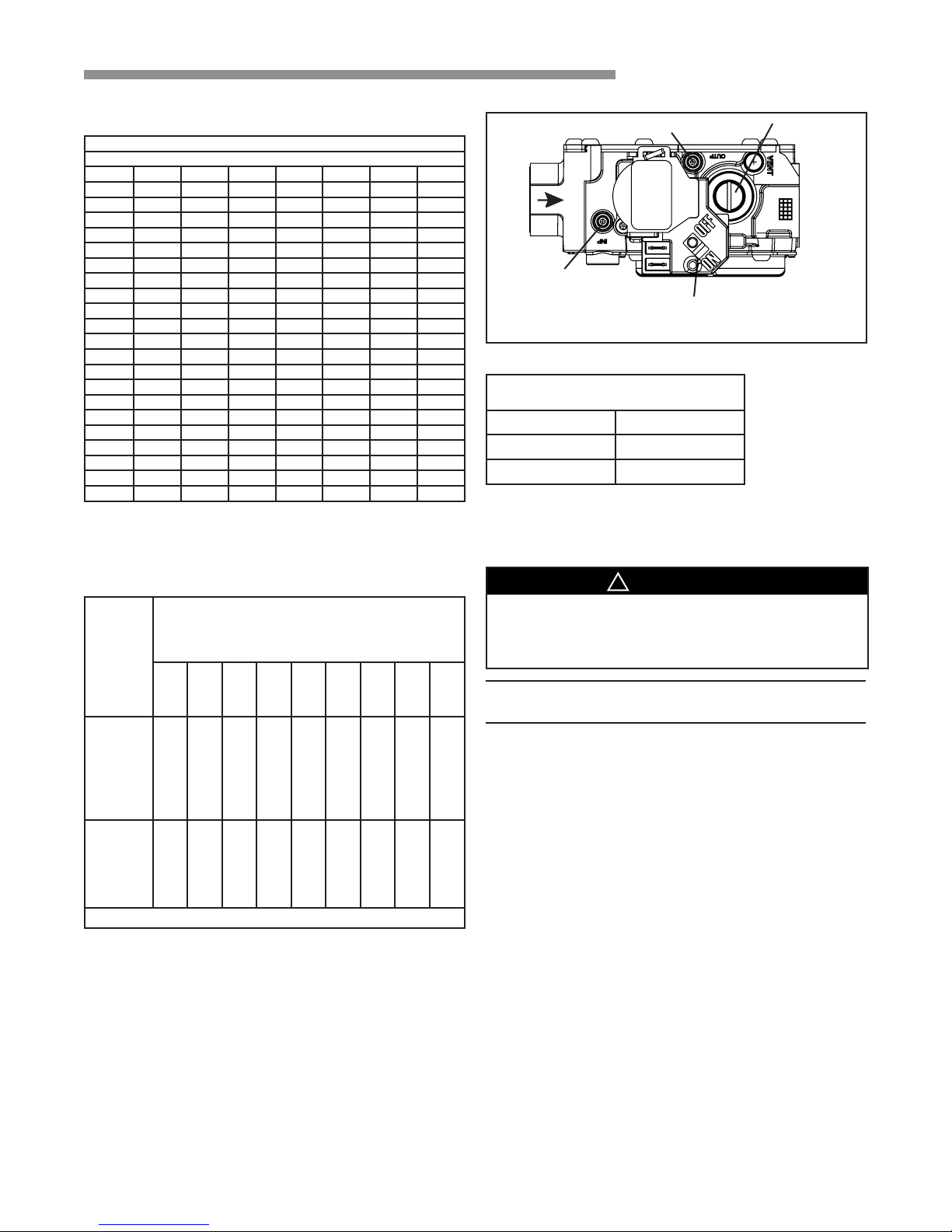
TABLE 12
GAS FLOW IN CUBIC FEET PER HOUR
SEC. FLOW SEC. FLOW SEC. FLOW SEC. FLOW
8 900 29 248 50 144 82 88
9 800 30 240 51 141 84 86
10 720 31 232 52 138 86 84
11 655 32 225 53 136 88 82
12 600 33 218 54 133 90 80
13 555 34 212 55 131 92 78
14 514 35 206 56 129 94 76
15 480 36 200 57 126 96 75
16 450 37 195 58 124 98 73
17 424 38 189 59 122 100 72
18 400 39 185 60 120 104 69
19 379 40 180 62 116 108 67
20 360 41 176 64 112 112 64
21 343 42 172 66 109 116 62
22 327 43 167 68 106 120 60
23 313 44 164 70 103 124 58
24 300 45 160 72 100 128 56
25 288 46 157 74 97 132 54
26 277 47 153 76 95 136 53
27 267 48 150 78 92 140 51
28 257 49 147 80 90 144 50
2 CUBIC FOOT DIAL
HIGH ALTITUDE DERATE
TABLE 13
Orifice
Twist
Drill
Size If
Installed
At Sea
Level
42
43
44
45
46
47
54
55
56
57
58
2000 3000 4000 5000 6000 7000 8000 9000 10000
From National Fuel Gas Code - Table F-4
ALTITUDE ABOVE SEA LEVEL
and Orifice Required At Other Elevations
42
43
43
43
44
44
45
46
44
44
44
45
45
46
47
47
45
45
45
46
47
47
48
48
46
47
47
47
48
48
49
49
47
47
47
48
48
49
49
50
48
48
49
49
49
50
50
51
54
55
55
55
55
55
56
56
55
55
55
56
56
56
56
56
56
56
57
57
57
58
59
59
58
59
59
60
60
61
62
63
59
60
60
61
62
62
63
63
47
48
50
50
51
52
56
57
60
63
64
Outlet Pressure Boss
i
Regulator
Adjust-
ment
Inlet Pressure
Boss (opt.)
On/Off Switch
White-Rodgers 36J gas valve
Table 14
FINAL MANIFOLD PRESSURE SET-
NATURAL GAS 3.5" W.C.
If the desired input rate cannot be achieved with a change
in manifold pressure, then the orices must be changed. LP
installations will require an orice change.
DO NOT attempt to manually light the burner.
Failure to follow this warning could result in
property damage, personal injury or death.
IMPORTANT: Re-install the propane orices to the same
depth as the orices supplied with the equipment.
See Table 13 for help in selecting orices if orice change is
required. Furnace input rate and temperature rise should be
checked again after changing orices to conrm the proper rate
for the altitude.
Installations above 4,000 feet may require a pressure switch
change. If required, use the BAYHALT*** Kit (High Altitude
Accessory Kit) listed in PRODUCT DATA.
TINGS (inches w.c.)
FUEL PRESSURE
LP GAS 10.5" W.C.
!
WARNING
▲
installed altitude. Input rate changes can be made by adjusting
the manifold pressure (min 3.0 - max 3.7 in. W.C. - Natural Gas)
or changing orices (orice change may not always be required).
Installation of this furnace at altitudes above 2,000 ft. (610m)
must be in accordance with local codes, or in the absence of
local codes, the National Fuel Gas Code, ANSI Z223.1/ NFPA
54 or National Standard of Canada, Natural Gas and Propane
Installation Code, CSA B149.1, and must be made in accordance
with the listed high Altitude Conversion Kit available with this
furnace.
18-CD34D1-5-EN 19
Page 20
INSTALLER’S GUIDE
WARNING
WARNING
LIGHTING INSTRUCTIONS
Lighting instructions appear on each unit. Each installation
must be checked out at the time of initial start up to insure
proper operation of all components. Check out should include
putting the unit through one complete cycle as outlined below.
Turn on the main electrical supply and set the thermostat above
the indicated temperature. The ignitor will automatically heat,
then the gas valve is energized to permit the ow of gas to the
burners. After ignition and ame is established, the ame control
module monitors the ame and supplies power to the gas valve
until the thermostat is satised.
To shut off
For complete shutdown: Move the control switch on the main
gas valve to the “OFF” position (See Figures 18). Disconnect the
electrical supply to the unit.
!
CAUTION
▲
If this is done during the cold weather months,
provisions must be taken to prevent freeze-up of
all water pipes and water receptacles.
Whenever your house is to be vacant, arrange to have someone
inspect your house for proper temperature. This is very
important in below freezing weather. If for any reason your
furnace should fail to operate damage could result, such as
frozen water pipes.
CONTROL AND SAFETY SWITCH
ADJUSTMENT
LIMIT SWITCH CHECK OUT
The limit switch is a safety device designed to close the gas valve
should the furnace become overheated. Since proper operation
of this switch is important to the safety of the unit, it must be
checked out on initial start up by the installer.
To check for proper operation of the limit switches, set the
thermostat to a temperature higher than the indicated temperature
to bring on the gas valve. Restrict the airow by blocking the
return air or by disconnecting the blower. When the furnace
reaches the maximum outlet temperature as shown on the rating
plate, the burners must shut off. If they do not shut off after a
reasonable time and overheating is evident, a faulty limit switch
is probable and the limit switch must be replaced. After checking
the operation of the limit control, be sure to remove the paper or
cardboard from the return air inlet, or reconnect the blower.
AIRFLOW ADJUSTMENT
Check inlet and outlet air temperatures to make sure they are
within the ranges specied on the furnace rating nameplate. If
the airow needs to be increased or decreased, see the wiring
diagram for information on changing the speed of the blower
motor.
!
▲
Disconnect power to the unit before removing the
blower door. Failure to follow this warning could
result in property damage, personal injury or
death.
This unit is equipped with a blower door switch which cuts power
to the blower and gas valve causing shutdown when the door is
removed. Operation with the door removed or ajar can permit the
escape of dangerous fumes. All panels must be securely closed at
all times for safe operation of the furnace.
NOTE: Direct drive motors have bearings which are
permanently lubricated and under normal use, lubrication is
not recommended
INDOOR BLOWER TIMING
The control module controls the indoor blower. The blower starts
approximately 45 seconds after ignition. The FAN-OFF period
is approximately 100 seconds from the interruption of gas ow.
ROOM AIR THERMOSTAT HEAT
ANTICIPATOR ADJUSTMENT
Set the thermostat heat anticipator according to the current ow
measured, or the settings found in the notes on the furnace wiring
diagram (found inside the furnace casing).
INSTRUCTIONS TO THE OWNERS
In the event that electrical, fuel, or mechanical failures occur,
the owner should immediately turn the gas supply off at the
manual gas valve, located in the burner compartment (See
Figure 17). Also turn off electrical power to the furnace and
contact the service agency designated by your dealer.
!
▲
Should overheating occur, or the gas supply fail
to shut off, shut off the gas valve to the unit before
shutting off the electrical supply. Failure to follow
this warning could result in property damage,
personal injury, or death.
OPERATING INFORMATION
FLAME ROLL-OUT DEVICE
All models are equipped with a thermal control device on the
burner cover. In case of ame roll-out, the device will cause the
circuit to open which shuts off all ow of gas.
Abnormal Conditions
1. EXCESSIVE COMBUSTION VENT PRESSURE OR
FLUE BLOCKAGE
If pressure against the induced draft blower outlet becomes
excessive, the pressure switch will shut off the gas valve
until acceptable combustion pressure is again available.
2. LOSS OF FLAME OR GAS SUPPLY FAILURE
If loss of ame occurs during a heating cycle (when ame is
not present at the sensor), the control module will retry the
20 18-CD34D1-5-EN
Page 21
Failure to follow safety warnings exactly, could
result in a fire or explosion causing property
damage, personal injury or loss of life.
—
Do not store or use gasoline or other flammable
vapors and liquids in the vicinity of this or any
other appliance.
— WHAT TO DO IF YOU SMELL GAS
• Do not try to light any appliance.
• Do not touch any electrical switch;
do not use any phone in your building.
• Immediately call your gas supplier from a
neighbor’s phone. Follow the gas supplier’s
instructions.
• If you cannot reach your gas supplier,
call the fire department.
— Installation and service must be performed by
a qualified installer, service agency or the gas
supplier.
▲
WARNING
!
▲
WARNING
!
The following warning complies with State of California law, Proposition 65.
This product contains fiberglass wool insulation!
Fiberglass dust and ceramic fibers are believed by
the State of California to cause cancer through
inhalation. Glasswool fibers may also cause
respiratory, skin, or eye irritation.
PRECAUTIONARY MEASURES
● Avoid breathing fiberglass dust.
● Use a NIOSH approved dust/mist respirator.
● Avoid contact with the skin or eyes. Wear long-
sleeved,
loose-fitting clothing, gloves, and eye protection.
● Wash clothes separately from other clothing: rinse
washer thoroughly.
● Operations such as sawing, blowing, tear-out, and
spraying may generate fiber concentrations
requiring
additional respiratory protection. Use the
appropriate
NIOSH approved respirator in these situations.
FIRST AID MEASURES
Eye Contact – Flush eyes with water to remove dust.
If symptoms persist, seek medical
attention.
Skin Contact – Wash affected areas gently with soap
and warm water after handling.
ignition sequence up to two times after the sensor cools. If
ignition is not achieved, it will lockout the furnace.
3. POWER FAILURE
If there is a power failure during a heating cycle, the system
will restart the ignition sequence automatically when power
is restored, if the thermostat still calls for heat.
4. INDUCED DRAFT BLOWER FAILURE
If pressure is not sensed by the pressure switch, it will not
allow the gas valve to open, therefore the unit will not start.
If failure occurs during a running cycle, the pressure switch
will cause the gas valve to close and shut the unit down.
INSTALLER’S GUIDE
INTEGRATED FURNACE CONTROL ERROR FLASH CODES
Flashing Slow --- Normal - No call for Heat
Flashing Fast --- Normal - Call for Heat
Continuous ON --- Replace IFC
Continuous OFF --- Check Power
2 Flashes --- System Lockout (Retries or Recycles exceeded)
Draft Pressure Error - Possible problems:
3 Flashes ---
4 Flashes --- Open Temperature Limit Circuit
5 Flashes --- Flame sensed when no ame should be present
6 Flashes --- 115 volt AC power reversed, poor grounding or system voltage too low
7 Flashes --- Gas valve circuit error
8 Flashes --- Low ame sense signal
18-CD34D1-5-EN 21
a) Venting problem
b) Pressure switch problem
c) Inducer problem
Page 22
INSTALLER’S GUIDE
22 18-CD34D1-5-EN
Ingersoll Rand
11819 N. Pennsylvania Street
Carmel, IN 46032
The manufacturer has a policy of continuous product and product
data improvement and it reserves the right to change design and
specications without notice.
 Loading...