

Ingersoll-Rand M801P080BU48AA, M801P060AU36AA, M801P060AU24AA, M801P080BU36AA, M801P100BU36AA Service Facts
...
SERVICE FACTS
Gas Furnaces
Upflow & Downflow – Induced Draft
1 Stage Heat
Models:
M801-SF-1C
M801P040AU24AA
M801P060AU24AA
M801P060AU36AA
M801P080BU36AA
M801P080BU48AA
M801P100BU36AA
M801P100CU48AA
M801P100CU60AA
M801P120DU60AA
M801P140DU60AA
M801P060AD24AA
M801P060AD36AA
M801P080BD45AA
M801P100CD48AA
M801P100CD60AA
M801P120DD60AA
M801P140DD60AA
IMPORTANT — This document contains a wiring diagram and service information. This is customer property and is to
remain with this unit. Please return to service information pack upon completion of work.
WARNING
MODEL
TYPE
RATINGS 2
Input BTUH 3
Capacity BTUH (ICS) 3
Temp. rise (Min.-Max.) °F.
BLOWER DRIVE
Diameter - Width (In.)
No. Used
Speeds (No.)
CFM vs. in. w.g.
Motor HP
R.P.M.
Volts / Ph / Hz
COMBUSTION FAN - Type
Drive - No. Speeds
Motor HP - RPM
Volts / Ph / Hz
FLA
FILTER — Furnished?
Type Recommended
Hi Vel. (No.-Size-Thk.)
VENT — Size (in.)
HEAT EXCHANGER
Type - Fired
- Unfired
Gauge (Fired)
ORIFICES — Main
Nat. Gas. Qty. — Drill Size
L.P. Gas Qty. — Drill Size
GAS VALVE
PILOT SAFETY DEVICE
Type
BURNERS — Type
Number
POWER CONN. — V / Ph / Hz 4
Ampacity (In Amps)
Max. Overcurrent Protection (Amps)
PIPE CONN. SIZE (IN.)
DIMENSIONS
Crated (In.)
WEIGHT
Shipping (Lbs.) / Net (Lbs.)
1 Central Furnace heating designs are certified to ANSI Z21.47 / CSA 2.3.
2 For U.S. applications, above input ratings (BTUH) are up to 2,000 feet, derate 4% per 1,000 feet for elevations above 2,000 feet above sea level. For Canadian applications,
above input ratings (BTUH) are up to 4,500 feet, derate 4% per 1,000 feet for elevations above 4,500 feet above sea level.
3 Based on U.S. government standard tests.
4 The above wiring specifications are in accordance with National Electrical Code; however, installations must comply with local codes.
M801P040AU24AA
Upflow / Horizontal
40,000
31,000
30 - 60
Direct
10 x 6
See Fan Performance Table
1/5
1080
115/1/60
Centrifugal
Direct - 1
1/50 - 3180
115/1/60
1.09
No
High Velocity
1 - 16x25 - 1 in.
4 Round
Alum. Steel
20
2 — 45
2 — 56
Redundant - Single Stage
Hot Surface Ignition
Multiport Inshot
115/1/60
5.4
15
1/2
H x W x D
41-3/4 x 16-1/2 x 30-1/2
119 / 110
DISCONNECT POWER BEFORE SERVICING
PRODUCT SPECIFICATIONS
M801P060AU24AA
Upflow / Horizontal
60,000
47,000
30 - 60
Direct
1
4
See Fan Performance Table
-
2
10 x 6**
1
4
1/3
1075
115/1/60
Centrifugal
Direct - 1
1/50 - 3180
115/1/60
1.09
No
High Velocity
1 - 16x25 - 1 in.
4 Round
Alum. Steel
20
3 — 45
3 — 56
Redundant - Single Stage
Hot Surface Ignition
Multiport Inshot
3
115/1/60
9.0
15
1/2
H x W x D
41-3/4 x 16-1/2 x 30-1/2
127 / 118
1
M801P060AU36AA
Upflow / Horizontal
60,000
47,000
30 - 60
Direct
10 x 6**
1
4
See Fan Performance Table
1/3
1075
115/1/60
Centrifugal
Direct - 1
1/50 - 3180
115/1/60
1.09
No
High Velocity
1 - 16x25 - 1 in.
4 Round
Alum. Steel
20
3 — 45
3 — 56
Redundant - Single Stage
Hot Surface Ignition
Multiport Inshot
3
115/1/60
9.0
15
1/2
H x W x D
41-3/4 x 16-1/2 x 30-1/2
127 / 118
M801P080BU36AA
Upflow / Horizontal
80,000
63,000
30 - 60
Direct
10 x 7
1
4
See Fan Performance Table
1/3
1075
115/1/60
Centrifugal
Direct - 1
1/50 - 3180
115/1/60
1.09
No
High Velocity
1 - 17x25 - 1 in.
4 Round
Alum. Steel
20
4 — 45
4 — 56
Redundant - Single Stage
Hot Surface Ignition
Multiport Inshot
4
115/1/60
9.0
15
1/2
H x W x D
41-3/4 x 19-1/2 x 30-1/2
142 / 132
NOTICE: The manufacturer has a policy of continuous product and product data improvement and
reserves the right to change design and specifications without notice.
© 2013 Ingersoll Rand All Rights Reserved
04/13

Service Facts
PRODUCT SPECIFICATIONS
MODEL
TYPE
RATINGS 2
Input BTUH 3
Capacity BTUH (ICS) 3
Temp. rise (Min.-Max.) °F.
BLOWER DRIVE
Diameter - Width (In.)
No. Used
Speeds (No.)
CFM vs. in. w.g.
Motor HP
R.P.M.
Volts / Ph / Hz
COMBUSTION FAN - Type
Drive - No. Speeds
Motor HP - RPM
Volts / Ph / Hz
FLA
FILTER — Furnished?
Type Recommended
Hi Vel. (No.-Size-Thk.)
VENT — Size (in.)
HEAT EXCHANGER
Type - Fired
- Unfired
Gauge (Fired)
ORIFICES — Main
Nat. Gas. Qty. — Drill Size
L.P. Gas Qty. — Drill Size
GAS VALVE
PILOT SAFETY DEVICE
Type
BURNERS — Type
Number
POWER CONN. — V / Ph / Hz 4
Ampacity (In Amps)
Max. Overcurrent Protection (Amps)
PIPE CONN. SIZE (IN.)
DIMENSIONS
Crated (In.)
WEIGHT
Shipping (Lbs.) / Net (Lbs.)
1 Central Furnace heating designs are certified to ANSI Z21.47 / CSA 2.3.
2 For U.S. applications, above input ratings (BTUH) are up to 2,000 feet, derate 4% per 1,000 feet for elevations above 2,000 feet above sea level. For Canadian applications,
above input ratings (BTUH) are up to 4,500 feet, derate 4% per 1,000 feet for elevations above 4,500 feet above sea level.
3 Based on U.S. government standard tests.
4 The above wiring specifications are in accordance with National Electrical Code; however, installations must comply with local codes.
MODEL
TYPE
RATINGS 2
Input BTUH 3
Capacity BTUH (ICS) 3
Temp. rise (Min.-Max.) °F.
BLOWER DRIVE
Diameter - Width (In.)
No. Used
Speeds (No.)
CFM vs. in. w.g.
Motor HP
R.P.M.
Volts / Ph / Hz
COMBUSTION FAN - Type
Drive - No. Speeds
Motor HP - RPM
Volts / Ph / Hz
FLA
FILTER — Furnished?
Type Recommended
Hi Vel. (No.-Size-Thk.)
VENT — Size (in.)
HEAT EXCHANGER
Type - Fired
- Unfired
Gauge (Fired)
ORIFICES — Main
Nat. Gas. Qty. — Drill Size
L.P. Gas Qty. — Drill Size
GAS VALVE
PILOT SAFETY DEVICE
Type
BURNERS — Type
Number
POWER CONN. — V / Ph / Hz 4
Ampacity (In Amps)
Max. Overcurrent Protection (Amps)
PIPE CONN. SIZE (IN.)
DIMENSIONS
Crated (In.)
WEIGHT
Shipping (Lbs.) / Net (Lbs.)
M801P080BU48AA
Upflow / Horizontal
80,000
64,000
30 - 60
Direct
10 x 8
1
See Fan Performance Table
Redundant - Single Stage
41-3/4 x 19-1/2 x 30-1/2
See Fan Performance Table
Redundant - Single Stage
4
1/3
1075
115/1/60
Centrifugal
Direct - 1
1/50 - 3180
115/1/60
1.09
No
High Velocity
1 - 17x25 - 1 in.
4 Round
Alum. Steel
20
4 — 45
4 — 56
Hot Surface Ignition
Multiport Inshot
4
115/1/60
9.8
15
1/2
H x W x D
142 / 132
M801P100CU60AA
Upflow / Horizontal
100,000
79,000
30 - 60
Direct
11 x 10
1
4
1/2
1075
115/1/60
Centrifugal
Direct - 1
1/50 - 3180
115/1/60
1.09
No
High Velocity
1 - 20x25 - 1 in.
4 Round
Alum. Steel
20
5 — 45
5 — 56
Hot Surface Ignition
Multiport Inshot
5
115/1/60
13.4
20
1/2
H x W x D
41-3/4 x 23 x 30-1/2
162 / 151
2 M801-SF-1C
M801P100BU36AA
See Fan Performance Table
Redundant - Single Stage
Hot Surface Ignition
41-3/4 x 19-1/2 x 30-1/2
M801P120DU60AA
See Fan Performance Table
Redundant - Single Stage
Hot Surface Ignition
41-3/4 x 26-1/2 x 30-1/2
1
Upflow / Horizontal
100,000
79,000
40 - 70
Direct
10 x 7
1
4
1/3
1075
115/1/60
Centrifugal
Direct - 1
1/50 - 3180
115/1/60
1.09
No
High Velocity
1 - 17x25 - 1 in.
4 Round
Alum. Steel
20
5 — 45
5 — 56
Multiport Inshot
5
115/1/60
9.0
15
1/2
H x W x D
151 / 141
Upflow / Horizontal
120,000
96,000
30 - 60
Direct
11 x 10
1
4
1/2
1075
115/1/60
Centrifugal
Direct - 1
1/50 - 3180
115/1/60
1.09
No
High Velocity
1 - 24x25 - 1 in.
4 Round
Alum. Steel
20
6 — 45
6 — 56
Multiport Inshot
6
115/1/60
13.4
20
1/2
H x W x D
186 / 174
M801P100CU48AA
Upflow / Horizontal
100,000
79,000
35 - 65
Direct
10 x 8
1
See Fan Performance Table
Redundant - Single Stage
M801P140DU60AA
See Fan Performance Table
Redundant - Single Stage
Hot Surface Ignition
41-3/4 x 26-1/2 x 30-1/2
4
1/2
1075
115/1/60
Centrifugal
Direct - 1
1/50 - 3180
115/1/60
1.09
No
High Velocity
1 - 20x25 - 1 in.
4 Round
Alum. Steel
20
5 — 45
5 — 56
Hot Surface Ignition
Multiport Inshot
5
115/1/60
11.6
15
1/2
H x W x D
41-3/4 x 23 x 30-1/2
162 / 151
Upflow / Horizontal
140,000
111,000
40 - 70
Direct
11 x 10
1
4
3/4
1075
115/1/60
Centrifugal
Direct - 1
1/50 - 3180
115/1/60
1.09
No
High Velocity
1 - 24x25 - 1 in.
4 Round
Alum. Steel
20
7 — 45
7 — 56
Multiport Inshot
7
115/1/60
13.8
20
1/2
H x W x D
193 / 181

Service Facts
PRODUCT SPECIFICATIONS
MODEL
TYPE
RATINGS 2
Input BTUH 3
Capacity BTUH (ICS) 3
Temp. rise (Min.-Max.) °F.
BLOWER DRIVE
Diameter - Width (In.)
No. Used
Speeds (No.)
CFM vs. in. w.g.
Motor HP
R.P.M.
Volts / Ph / Hz
COMBUSTION FAN - Type
Drive - No. Speeds
Motor HP - RPM
Volts / Ph / Hz
FLA
FILTER — Furnished?
Type Recommended
Hi Vel. (No.-Size-Thk.)
VENT — Size (in.)
HEAT EXCHANGER
Type - Fired
- Unfired
Gauge (Fired)
ORIFICES — Main
Nat. Gas. Qty. — Drill Size
L.P. Gas Qty. — Drill Size
GAS VALVE
PILOT SAFETY DEVICE
Type
BURNERS — Type
Number
POWER CONN. — V / Ph / Hz 4
Ampacity (In Amps)
Max. Overcurrent Protection (Amps)
PIPE CONN. SIZE (IN.)
DIMENSIONS
Crated (In.)
WEIGHT
Shipping (Lbs.) / Net (Lbs.)
1 Central Furnace heating designs are certified to ANSI Z21.47 / CSA 2.3.
2 For U.S. applications, above input ratings (BTUH) are up to 2,000 feet, derate 4% per 1,000 feet for elevations above 2,000 feet above sea level. For Canadian applications,
above input ratings (BTUH) are up to 4,500 feet, derate 4% per 1,000 feet for elevations above 4,500 feet above sea level.
3 Based on U.S. government standard tests.
4 The above wiring specifications are in accordance with National Electrical Code; however, installations must comply with local codes.
MODEL
TYPE
RATINGS 2
Input BTUH 3
Capacity BTUH (ICS) 3
Temp. rise (Min.-Max.) °F.
BLOWER DRIVE
Diameter - Width (In.)
No. Used
Speeds (No.)
CFM vs. in. w.g.
Motor HP
R.P.M.
Volts / Ph / Hz
COMBUSTION FAN - Type
Drive - No. Speeds
Motor HP - RPM
Volts / Ph / Hz
FLA
FILTER — Furnished?
Type Recommended
Hi Vel. (No.-Size-Thk.)
VENT — Size (in.)
HEAT EXCHANGER
Type - Fired
- Unfired
Gauge (Fired)
ORIFICES — Main
Nat. Gas. Qty. — Drill Size
L.P. Gas Qty. — Drill Size
GAS VALVE
PILOT SAFETY DEVICE
Type
BURNERS — Type
Number
POWER CONN. — V / Ph / Hz 4
Ampacity (In Amps)
Max. Overcurrent Protection (Amps)
PIPE CONN. SIZE (IN.)
DIMENSIONS
Crated (In.)
WEIGHT
Shipping (Lbs.) / Net (Lbs.)
M801P060AD24AA
Downflow / Horizontal
60,000
48,000
35 - 65
DIRECT
10 x 7
1
See Fan Performance Table
Redundant - Single Stage
41-3/4 x 16-1/2 x 30-1/2
Downflow / Horizontal
See Fan Performance Table
Redundant - Single Stage
4
1/5
1075
115/1/60
Centrifugal
Direct - 1
1/50 - 3180
115/1/60
1.09
No
High Velocity
2 - 14x20 - 1in.
4 Round
Alum. Steel
20
3 — 45
3 — 56
Hot Surface Ignition
Multiport Inshot
3
115/1/60
5.5
15
1/2
H x W x D
129 / 119
M801P100CD60AA
100,000
80,000
30 - 60
DIRECT
11 x 10
1
4
1/2
1075
115/1/60
Centrifugal
Direct - 1
1/50 - 3180
115/1/60
1.09
No
High Velocity
2 - 16x20 - 1 in.
4 Round
Alum. Steel - Type I
20
5 — 45
5 — 56
Hot Surface Ignition
Multiport Inshot
5
115/1/60
12.8
15
1/2
H x W x D
41-3/4 x 23 x 30-1/2
167 / 155
M801-SF-1C 3
M801P060AD36AA
Downflow / Horizontal
60,000
48,000
30 - 60
DIRECT
11 x 7
1
See Fan Performance Table
Redundant - Single Stage
41-3/4 x 16-1/2 x 30-1/2
Downflow / Horizontal
See Fan Performance Table
Redundant - Single Stage
41-3/4 x 26-1/2 x 30-1/2
4
1/2
1075
115/1/60
Centrifugal
Direct - 1
1/50 - 3180
115/1/60
1.09
No
High Velocity
2 - 14x20 - 1in.
4 Round
Alum. Steel
20
3 — 45
3 — 56
Hot Surface Ignition
Multiport Inshot
3
115/1/60
11.6
15
1/2
H x W x D
129 / 119
M801P120DD60AA
120,000
96,000
35 - 65
DIRECT
11 x 10
1
4
1/2
1075
115/1/60
Centrifugal
Direct - 1
1/50 - 3180
115/1/60
1.09
No
High Velocity
2 - 16x20 - 1 in.
4 Round
Alum. Steel - Type I
20
6 — 45
6 — 56
Hot Surface Ignition
Multiport Inshot
6
115/1/60
12.8
15
1/2
H x W x D
189 / 176
1
M801P080BD45AA
Downflow / Horizontal
80,000
64,000
35 - 65
DIRECT
10 x 8
1
See Fan Performance Table
Redundant - Single Stage
41-3/4 x 19-1/2 x 30-1/2
Downflow / Horizontal
See Fan Performance Table
Redundant - Single Stage
41-3/4 x 26-1/2 x 30-1/2
4
1/3
1075
115/1/60
Centrifugal
Direct - 1
1/50 - 3180
115/1/60
1.09
No
High Velocity
2 - 14x20 - 1 in.
4 Round
Alum. Steel - Type I
20
4 — 45
4 — 56
Hot Surface Ignition
Multiport Inshot
4
115/1/60
9.1
15
1/2
H x W x D
146 / 135
M801P140DD60AA
140,000
113,000
45 - 75
DIRECT
11 x 10
1
4
3/4
1075
115/1/60
Centrifugal
Direct - 1
1/50 - 3180
115/1/60
1.09
No
High Velocity
2 - 16x20 - 1in.
4 Round
Alum. Steel
20
7 — 45
7 — 56
Hot Surface Ignition
Multiport Inshot
7
115/1/60
13.8
20
1/2
H x W x D
196 / 183
M801P100CD48AA
Downflow / Horizontal
100,000
80,000
35 - 65
DIRECT
10 x 8
1
See Fan Performance Table
Redundant - Single Stage
4
1/2
1075
115/1/60
Centrifugal
Direct - 1
1/50 - 3180
115/1/60
1.09
No
High Velocity
2 - 16x20 - 1in.
4 Round
Alum. Steel
20
5 — 45
5 — 56
Hot Surface Ignition
Multiport Inshot
5
115/1/60
11.6
15
1/2
H x W x D
41-3/4 x 23 x 30-1/2
166 / 154
Service Facts
▲
WARNING
!
▲
CAUTION
!
▲
WARNING
!
▲
WARNING
!
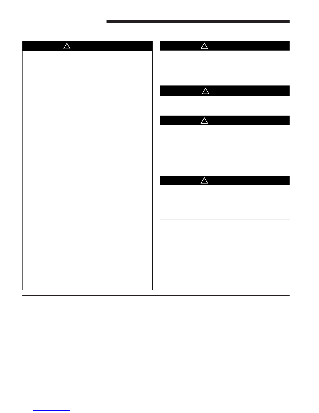
CARBON MONOXIDE POISONING HAZARD
Failure to follow the steps outlined below for each
appliance connected to the venting system being
placed into operation could result in carbon monoxide
poisoning or death.
The following steps shall be followed for each appliance
connected to the venting system being placed into
operation, while all other appliances connected to the
venting system are not in operation:
1. Seal any unused openings in the venting system.
2. Inspect the venting system for proper size and
horizontal pitch, as required in the National Fuel Gas
Code, ANSI Z223.1/NFPA 54 or the CAN/CGA B149
Installation Codes and these instructions. Determine
that there is no blockage or restriction, leakage,
corrosion and other deficiencies which could cause an
unsafe condition.
3. As far as practical, close all building doors and
windows and all doors between the space in which the
appliance(s) connected to the venting system are
located and other deficiencies which could cause an
unsafe condition.
4. Close fireplace dampers.
5. Turn on clothes dryers and any appliance not
connected to the venting system. Turn on any exhaust
fans, such as range hoods and bathroom exhausts, so
they are operating at maximum speed. Do not operate
a summer exhaust fan.
6. Follow the lighting instructions. Place the appliance
being inspected into operation. Adjust the thermostat
so appliance is operating continuously.
7. If improper venting is observed during any of the above
tests, the venting system must be corrected in
accordance with the National Fuel Gas Code,
ANSI Z221.1/NFPA 54 and/or CAN/CGA B149
Installation Codes.
8. After it has been determined that each appliance
connected to the venting system properly vents where
tested as outlined above, return doors, windows,
exhaust fans, fireplace dampers and any other gas-fired
burning appliance to their previous conditions of use.
▲
WARNING
!
SEQUENCE OF OPERATION
THERMOSTAT CALL FOR HEAT
R and W thermostat contacts close signaling the control
module to run its self-check routine. After the control
module has verified that the pressure switch contacts are
open and the limit switch(es) contacts are closed, the draft
blower will be energized.
As the induced draft blower comes up to speed, the pressure
switch contacts will close and the ignitor warm up period
will begin. The ignitor will heat for approx. 17 seconds,
then the gas valve is energized to permit gas flow to the
burners. The flame sensor confirms that ignition has been
achieved within the 4 second ignition trial period.
4 M801-SF-1C
SAFETY SECTION
The cabinet must have an uninterrupted or unbroken
ground according to National Electrical Code, ANSI/NFPA
70 - “latest edition” and Canadian Electrical Code, CSA
C22.1 or local codes to minimize personal injury if an
electrical fault should occur. A failure to follow this warning could result in an electrical shock, fire, injury, or death.
The integrated furnace control is polarity sensitive. The
hot leg of the 115 VAC power must be connected to the
BLACK field lead.
FIRE OR EXPLOSION HAZARD
Failure to follow the safety warnings exactly could result
in serious injury, death or property damage.
Never test for gas leaks with an open flame. Use a commercially available soap solution made specifically for
the detection of leaks to check all connections. A fire or
explosion may result causing property damage, personal
injury, or loss of life.
FIRE OR EXPLOSION HAZARD
Failure to follow the safety warnings exactly could result
in serious injury, death or property damage.
Improper servicing could result in dangerous operation,
serious injury, death, or property damage.
After the flame sensor confirms that ignition has been
achieved, the delay to fan ON period begins timing and
after approx. 45 seconds the indoor blower motor will be
energized and will continue to run during the heating cycle.
When the thermostat is satisfied, R and W thermostat
contacts open, the gas valve will close, the flames will extinguish, and the induced draft blower will be de-energized.
The indoor blower motor will continue to run for the fan off
period (Field selectable at 60, 100, 140 or 180 seconds), then
will be de-energized by the control module.
 Loading...