

Ingersoll-Rand HC-3, HC-6, HC-7, HC-9, HC-14 User Manual
...
U
U
s
s
err
e
M
M
a
a
n
n
u
u
all
a
SERIES HC
Heat-of-Compression
Compressed Air Dryer
Models HC-3 – HC-239
IMPORTANT! BEFORE INSTALLING AND
OPERATING THE DRYER, IT IS
RECOMMENDED THAT THIS
MANUAL BE STUDIED AND
CLEARLY UNDERSTOOD.
THIS DRYER IS DESIGNED TO BE
USED ONLY WITH A NONLUBRICATED COMPRESSOR.
USE WITH A LUBRICATED
COMPRESSOR WILL VOID ALL
WARRANTIES AND MAY CAUSE
SEVERE DAMAGE.
Information
When making inquiries,
please provide the following
information:
1) Equipment Model Number
2) Equipment Serial Number
3) Equipment Operating
Pressure
4) Equipment Operating
Temperature
5) Approximate time in
service
6) Nature of Problem
For information, parts,
or service, contact your
local IInnggeerrssoollll--RRaanndd
Service provider or
reach us at
www.air.irco.com

USER MANUAL
Series HC
Reference IR - 222 Rev 3
Page 2 10/17/2013

USER MANUAL
Series HC
PREFACE
SECTION 1: INTRODUCTION
1.1 General Information
1.2 Safety Instructions
1.3 Personnel Qualification
1.4 Product Information
SECTION 2: INSTALLATION
2.1 Set-up and installation
1.2.1 Identification of signs and symbols in this manual
1.2.2 Safety tips for maintenance, inspection & assembly work
1.4.1 Theory of operation
1.4.2 Pressure vessel regulations
1.4.3 Airtightness test
1.4.4 Overloading
1.4.5 Technical data sheet
1.4.6 Dryer flow capacities
1.4.7 Transport
1.4.8 Storage
1.4.9 Use of a pre and afterfilter
2.1.1 Mechanical installation
2.1.2 Preventative maintenance prior to start-up
2.1.3 Filter installation
2.1.4 Electrical installation
INDEX
Reference IR - 222 Rev 3
Page 3 10/17/2013

USER MANUAL
Series HC
SECTION 3: START UP AND OPERATION
3.1 Start-up
3.1.1 Pressurizing dryer
3.2 Operator interface
SECTION 4: MAINTENANCE
4.1 Suggested preventive maintenance schedule
4.1.1 Introduction
4.1.2 Periodic maintenance schedule
4.2 Replacement / Disposal of the desiccant
4.2.1 For first time fill-up
4.2.2 To replace used desiccant
4.3 Dew point meter maintenance (DPDS Option only)
4.4 Afterfilter
4.4.1 General comments and use
4.4.2 Function
4.4.3 Assembly and installation
4.4.4 Maintenance
4.4.5 Changing of afterfilter elements
4.5 Filter Accessories
Reference IR - 222 Rev 3
Page 4 10/17/2013

USER MANUAL
Series HC
SECTION 5: TROUBLESHOOTING AND FAULTS
5.1 Introduction
5.2 High Dew Point
5.2.1 Changed operating conditions
5.2.2 Old desiccant
5.2.3 Towers not reversing
5.2.4 Cooler discharge air temperature too high
5.2.5 Dew point indication in error
5.2.6 Two-way valve leakage
5.3 Fail-to-shift
5.3.1 Solenoid valve failed to operate
5.3.2 Pilot air tubing leakage
5.3.3 Two-way switching valve actuator leakage
5.4 Primary Drain Failure
5.4.1 Plugging or sticking due to foreign matter
5.5 Secondary Drain Failure
5.5.1 Solenoid valve failure
5.5.2 Liquid level probe failure
5.6 Short-term shut-down
5.7 Shut-down in case of a fault or for maintenance
SECTION 6: SPECIFICATIONS, PARTS LIST(S), & DATA REPORTS
SECTION 7: AUXILIARY MANUALS (IF APPLICABLE)
SECTION 8: CUT SHEETS
SECTION 9: DRAWINGS
Reference IR - 222 Rev 3
Page 5 10/17/2013

USER MANUAL
Series HC
PREFACE:
This technical manual from IInnggeerrssoollll--RRaanndd®® is an aid in getting to know the adsorption
dryer better and in utilizing its possibilities for application in accordance with its
intended use. Furthermore, this manual contains important information for safe,
proper and economic operation.
All instructions must be followed as written in order to avoid danger and damages
which could cause downtime and premature wear and tear on the adsorption dryer.
In addition to the technical manual and the accident prevention regulations which are
valid in the particular location where the dryer is being used, the recognized special
rules for safe and proper working procedures must also be followed.
Each person involved with the set-up, start-up, operation, maintenance and repair of
the adsorption dryer in the User Company must have first read and understood the
technical manual and especially the safety tips.
Reference IR - 222 Rev 3
Page 6 10/17/2013
USER MANUAL
Series HC
Prior to installation and start-up of this dryer,
please read and implement this section.
SECTION 1
INTRODUCTION
Reference IR - 222 Rev 3
Page 7 10/17/2013

USER MANUAL
Series HC
SECTION 1:
1.1 GENERAL INFORMATION
The adsorption dryer of the HC-3 – HC-239 series is built according to the latest
technological developments and recognized safety rules. Its use, however, can
endanger life and limb of the user or of third parties and can lead to considerable
damage to the adsorption dryer and other material assets if:
it is operated by personnel not trained or instructed in its use,
it is improperly used,
It is improperly maintained or serviced.
INTRODUCTION
This can result in the loss of all damage claims.
This adsorption dryer is designed for neutral media (gas) free of aggressive water,
oil and solid elements. IInnggeerrssoollll--RRaanndd®® accepts no liability for corrosion damage and
malfunctions caused by aggressive media.
Applications other than those mentioned in this manual must be agreed to by
IInnggeerrssoollll--RRaanndd®
® and confirmed in writing.
In the interest of further development, IInnggeerrssoollll--RRaanndd®® reserves the right to make
changes at any time, which, in keeping with the essential characteristics of the
adsorption dryer described here, may be necessary for increasing efficiency or for
reasons relating to safety or to normal business practice.
1.2 SAFETY INSTRUCTIONS
This technical manual contains basic tips, which must be followed during set-up,
operation and servicing. It is of utmost importance that it be read by the assembly
technician before installation and start-up, as well as by the specialist / operator in
charge, and it must always be within reach at the place where the adsorption dryer
is being used.
Reference IR - 222 Rev 3
Page 8 10/17/2013

USER MANUAL
Series HC
SECTION 1: (Continued)
1.2.1 Identification of signs and symbols in this technical manual
The safety tips contained in this technical manual, whose disregard could endanger
people and machines, are indicated by a general danger sign and the additional
markings Danger! or Attention!
Danger! / Attention!
Warning against electrical voltage!
Safety tips printed directly on the adsorption dryer must also be followed at all times
and must be kept completely legible.
Advice: This sign refers to a procedure or sequence of particular
interest or importance. All tips must be followed to ensure
proper use of this adsorption dryer.
This dot refers to working or operational steps. The steps are to be carried out in
the order of their appearance from top to bottom.
- The sign of a hyphen marks enumerations.
Reference IR - 222 Rev 3
Page 9 10/17/2013

USER MANUAL
Series HC
SECTION 1: (Continued)
1.2.2 Safety tips for maintenance, inspection and assembly work
The operator is to make sure that all maintenance, inspection and assembly work is
carried out by special personnel who are authorized and qualified, and who are
adequately informed through careful study of the technical manual. For this reason,
special attention should be paid to the following attention and danger sign:
Attention!
Never make structural changes to the adsorption dryer that are
not specifically authorized by Ingersoll-Rand!
Only use original spare and accessory parts!
Carry out maintenance work only when the adsorption dryer is
switched off, depressurized, and disconnected from the electric
power supply!
Attention!
Multiple power sources may exist in the electrical panel. All
possible power sources must be disconnected before servicing
dryer.
Advice: Refer to the desiccant material safety data sheet (MSDS) when
installing or disposing of desiccant, which can be found in
Section 8 of this User Manual.
Danger!
Wear protective goggles and mask when working with the desiccant!
Advice for protection:
If desiccant comes into contact with the eyes, rinse eyes immediately with large
amounts of clear water.
If the desiccant is spilled, clean up with effort to minimize the formation of dust.
In case of fire, there is no restriction on the use of fire extinguishing material.
A small dust mask must be worn.
Reference IR - 222 Rev 3
Page 10 10/17/2013
Danger!
Do not attempt to service or maintain dryer while system is hot!

USER MANUAL
Series HC
SECTION 1: (Continued)
1.3 PERSONNEL QUALIFICATION
The personnel involved in operation, maintenance, inspection, and assembly must
have the corresponding qualifications to do this work. Areas of responsibility and
supervision of the personnel must be precisely established by the operator. Should
the personnel not possess the necessary knowledge, then they must be trained and
instructed. If need be, this training may be carried out by the manufacturer / supplier
at the request of the operator of the adsorption dryer. Further, the operator is to
make sure that the personnel completely understand the contents of the technical
manual.
1.4 PRODUCT INFORMATION
The adsorption dryer is used for the purpose of drying compressed air and other
gases according to its respective design. As a "standard model" the adsorption dryer
is equipped with two desiccant vessels and, depending on certain conditions,
provides pure, dry and oil-free compressed air or gases.
1.4.1 Theory of Operation
The HC heat-of-compression dryer uses the hot air from the compressor to
regenerate the desiccant. Each tower is sized for a minimum of 4 hours online,
but may be extended by use of the optional DPDS which will allow the dryer to
switch towers based on water load rather than time.
The DPDS (Dew Point Demand System) is optional equipment and may or may
not be present on this particular air dryer. If the dryer is equipped with the DPDS,
see the associated DPDS Instruction Manual included in Section 7 for more
operational details.
The regeneration cycle is split up into three functions.
Reference IR - 222 Rev 3
Page 11 10/17/2013
USER MANUAL
Series HC
SECTION 1: (Continued)
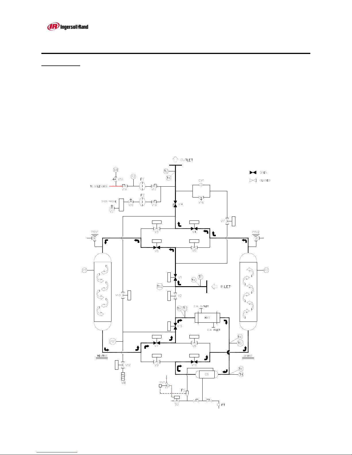
A. Regeneration Cycles
1. Heating. Hot air directly from the compressor enters the inlet of the HC
and is directed by the inlet 2-way valves into the regenerating tower. This
hot, thirsty air regenerates the bulk of the water from the desiccant. The
air is then directed into the aftercooler where it is cooled, the coalescing
separator where liquid water is removed through the drain trap system,
then into the drying tower where the air is actually dried to its final low
dew point. The heating cycle lasts 90 minutes.
Reference IR - 222 Rev 3
Page 12 10/17/2013
USER MANUAL
Series HC
SECTION 1: (Continued)
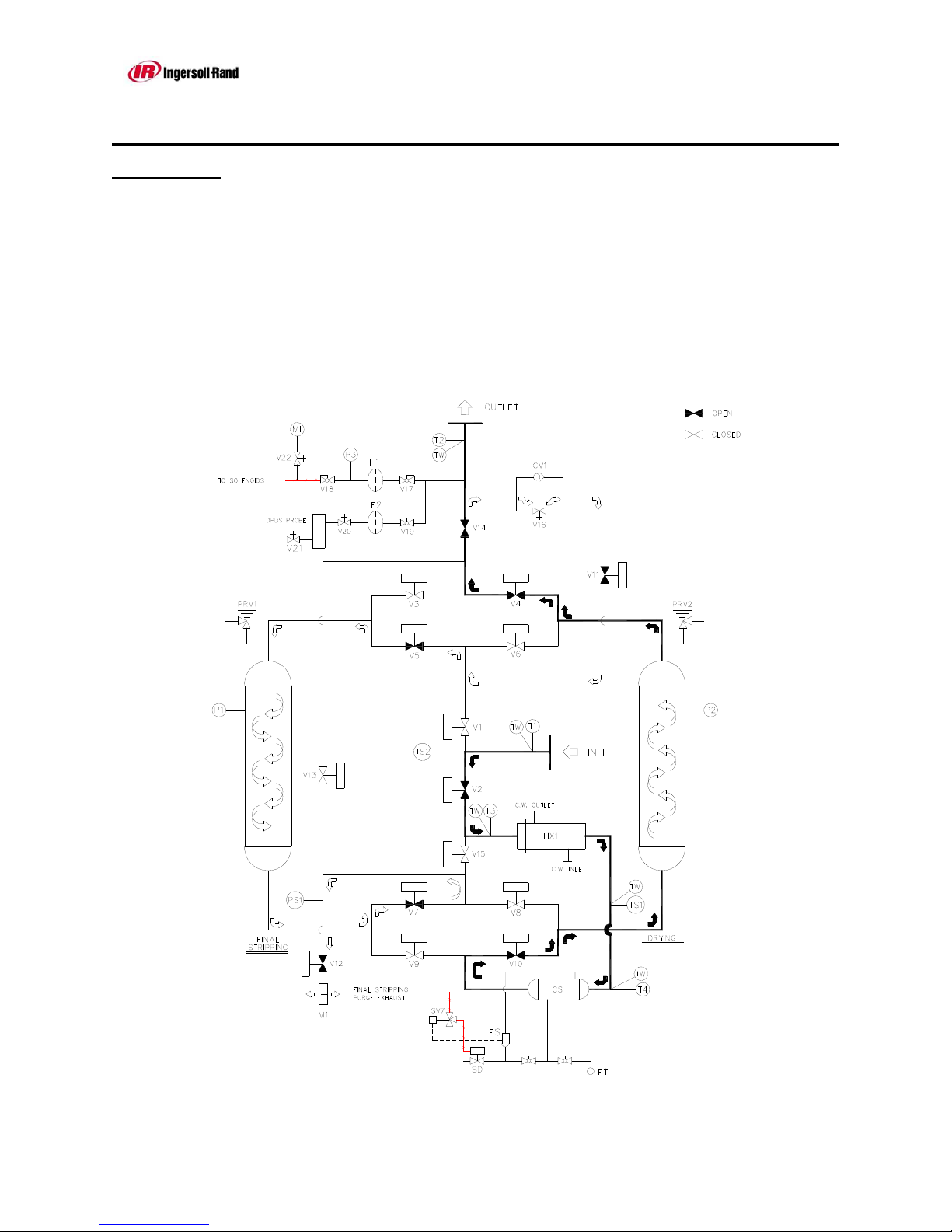
2. Stripping. At the end of heating, the inlet valves shift position, directing
the hot inlet air directly into the aftercooler, separator, and drying tower.
We now begin stripping. The stripping phase of regeneration lasts 90
minutes. At the beginning of stripping, the regenerating tower is
depressurized through a muffler. During stripping, a small adjustable flow
of dry air is used to remove the last little bit of moisture from the
regenerating tower. If dryer is equipped with optional trim heater,
reference operational instructions in Addendum at back of manual.
Reference IR - 222 Rev 3
Page 13 10/17/2013
USER MANUAL
Series HC
SECTION 1: (Continued)
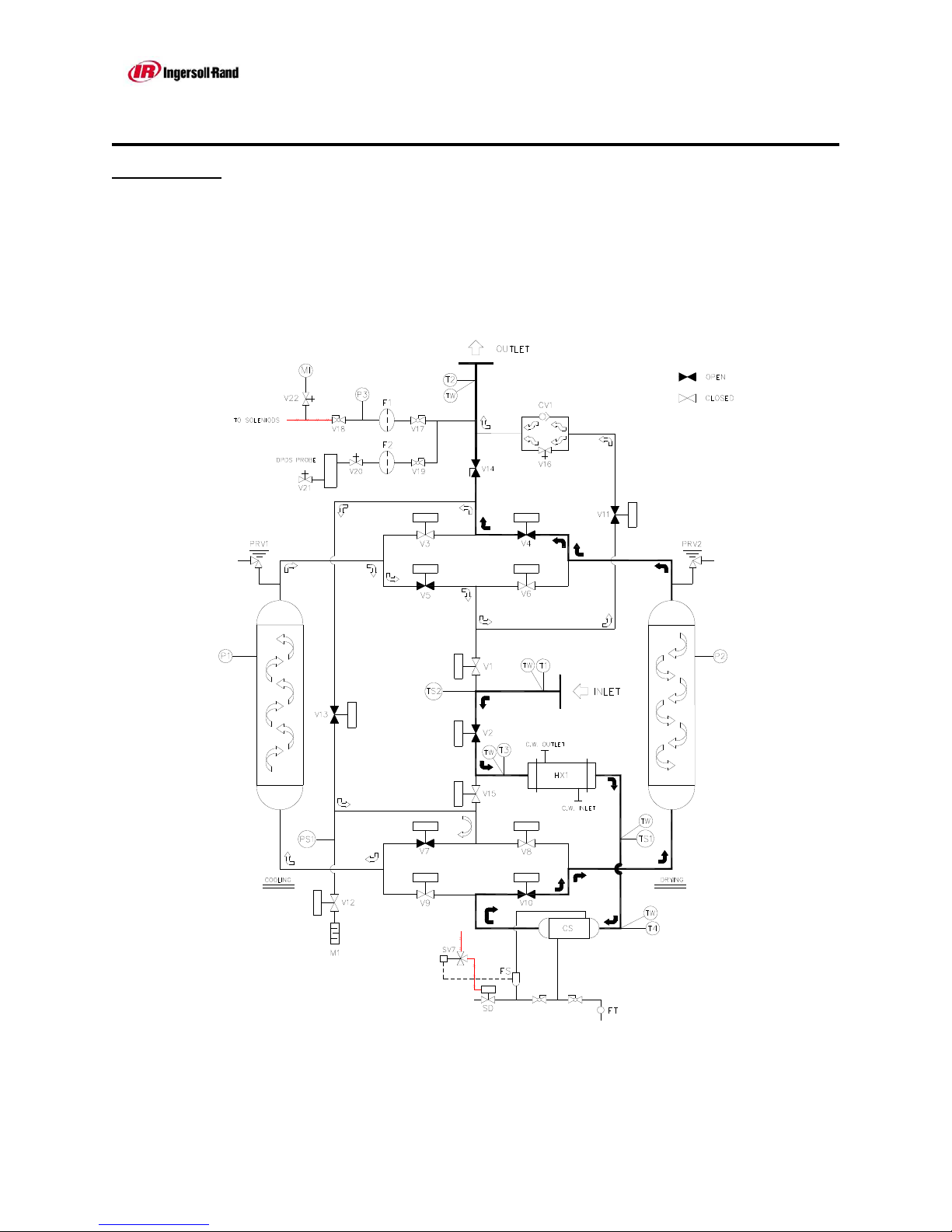
3. Cooling. At the end of stripping, the regenerating tower is repressurized.
The cooling cycle valves open and cooling begins. The cooling cycle lasts
60 minutes. During cooling, a portion of the dry outlet air is directed into
the regenerating tower to reduce the temperature of the bed prior to
tower shift.
Reference IR - 222 Rev 3
Page 14 10/17/2013
USER MANUAL
Series HC
SECTION 1: (Continued)
1.4.2 Pressure vessel regulations
The pressure vessels are designed according to the standard technical
requirements. They fulfill the test of the certifying procedure and carry the “U”,
“UM” ASME Symbol.
Range of Application:
Type HC-3 – HC-239
Operating overpressure
Operating temperature
1.4.3 Airtightness test
All adsorption dryers are subjected to an airtightness test prior to shipment using
compressed air.
1.4.4 Overloading
Max. 150 PSIG
10.34 Bar(g)
Max.
Min.
500°F
260°C
20°F
-6.67°C
Attention!
Never weld on or alter a pressure vessel in any
way!
Reference IR - 222 Rev 3
Page 15 10/17/2013
Attention!
Protect the adsorption dryer from overloads!
The adsorption dryer can become overloaded, if:
The inlet flow is too high,
The temperature of the air at the discharge of the
aftercooler is too high,
The min. operating pressure is too low,
The temperature of the air at the discharge of the
compressor is too low.
USER MANUAL
Series HC
SECTION 1: (Continued)
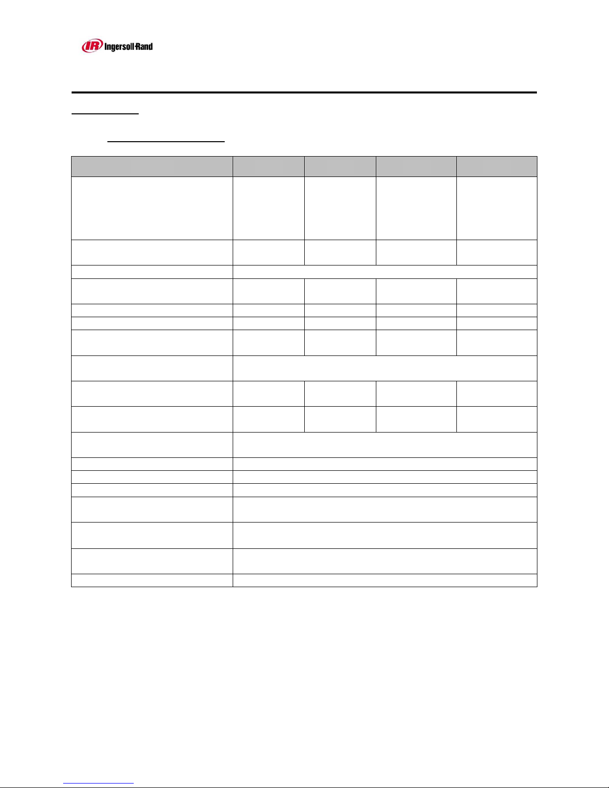
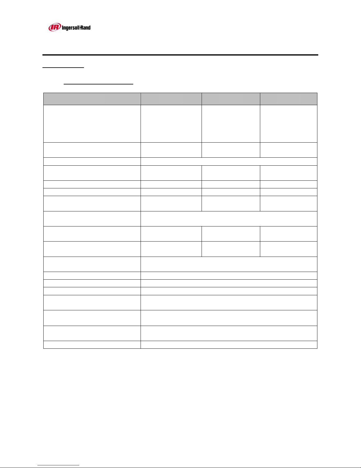
1.4.5 Technical data sheet
MODEL HC-3 HC-6 HC-7 HC-9
Flow:
(SCFM) @ 100 PSIG
100°F Drying Temperature
(m3/hr) @ 6.89Bar(g)
301
511
535
909
677
1150
37.8°C Drying Temperature
Vessel OD 12”
30.48 cm
16”
40.64 cm
18”
45.72 cm
Desiccant type IR Activated Alumina
Desiccant / Vessel 223 lbs
101 kgs
397 lbs
180 kgs
502 lbs
228 kgs
Inlet connection 2 NPT 2 NPT 3 FLG 3 FLG
Outlet connection 2 NPT 2 NPT 3 FLG 3 FLG
Afterfilter
(* Option)
AF-350
or AFH-350*
AF-550
or HAF-550*
AF-1000
or HAF-1000*
or HAF-1000*
Voltage 115/1/60 Standard
Consult Factory for other voltages
Cooling Water 9 GPM
34 LPM
Stripping Flow 6 SCFM
10 m3/hr
16 GPM
61 LPM
11 SCFM
19 m3/hr
20 GPM
76 LPM
14 SCFM
24 m3/hr
Cycle time 8 Hour NEMA Cycle –
4 Hours drying/ 4 Hours Regeneration
Outlet Dew Point Variable
DPDS Control Adjustable
High Humidity Alarm Adjustable
Pressure Switch Setpoints 10 PSI Fail to Shift 60 PSI Initiate Cooling
.7 Bar Fail to Shift 4 Bar Initiate Cooling
Cooler outlet high temperature
alarm
Low regeneration temperature
105F
40.6°C
Adjustable
alarm
Process flow Downward Regeneration / Upward Drying
836
1420
20”
50.8 cm
620 lbs
281 kgs
AF-1000
25 GPM
95 LPM
17 SCFM
29 m3/hr
Reference IR - 222 Rev 3
Page 16 10/17/2013
USER MANUAL
Series HC
SECTION 1: (Continued)
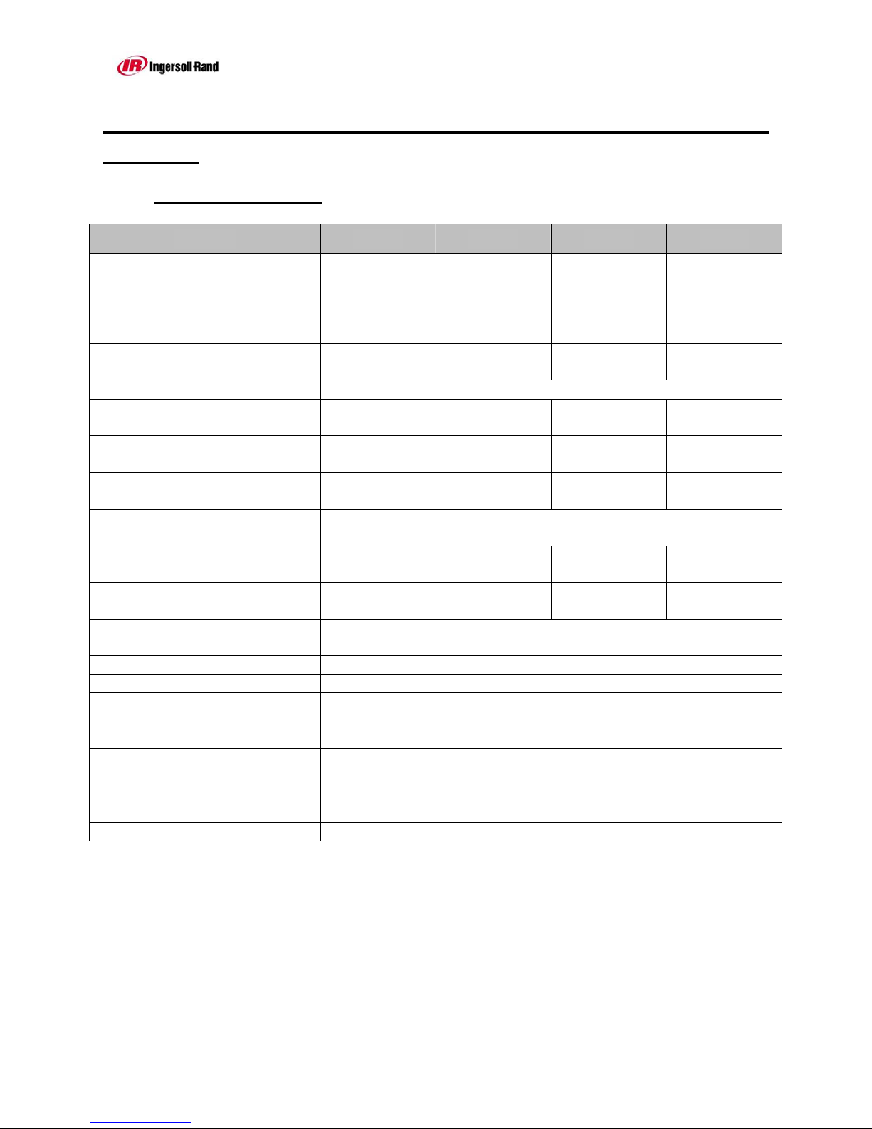
1.4.5 Technical data sheet
MODEL HC-14 HC-21 HC-30 HC-41
Flow:
(SCFM) @ 100 PSIG
100°F Drying Temperature
(m3/hr) @ 6.89Bar(g)
1204
2046
1880
3194
2708
4601
37.8°C Drying Temperature
Vessel OD 24”
60.96 cm
30”
76.2 cm
36”
91.44 cm
Desiccant type IR Activated Alumina
Desiccant / Vessel 893 lbs
405 kgs
1395 lbs
633 kgs
2009 lbs
911 kgs
Inlet connection 3 FLG 4 FLG 4 FLG 6 FLG
Outlet connection 3 FLG 4 FLG 4 FLG 6 FLG
Afterfilter
(* Option)
AF-1400
or HAF-1400*
AF-2400
or HAF-2400*
AF-3600
or HAF-3600*
or HAF-7200*
Voltage 115/1/60 Standard
Consult Factory for other voltages
Cooling Water 36 GPM
136 LPM
Stripping Flow 24 SCFM
41 m3/hr
56 GPM
212 LPM
38 SCFM
65 m3/hr
80 GPM
303 LPM
54 SCFM
92 m3/hr
Cycle time 8 Hour NEMA Cycle –
4 Hours drying/ 4 Hours Regeneration
Outlet Dew Point Variable
DPDS Control Adjustable
High Humidity Alarm Adjustable
Pressure Switch Setpoint 10 PSI Fail to Shift 60 PSI Initiate Cooling
.7 Bar Fail to Shift 4 Bar Initiate Cooling
Cooler outlet high temperature
alarm
Low regeneration temperature
105F
40.6°C
Adjustable
alarm
Process flow Downward Regeneration / Upward Drying
3686
6263
42”
106.7 cm
2735 lbs
1241 kgs
AF-7200
110 GPM
416 LPM
74 SCFM
126 m3/hr
Reference IR - 222 Rev 3
Page 17 10/17/2013
USER MANUAL
Series HC
SECTION 1: (Continued)
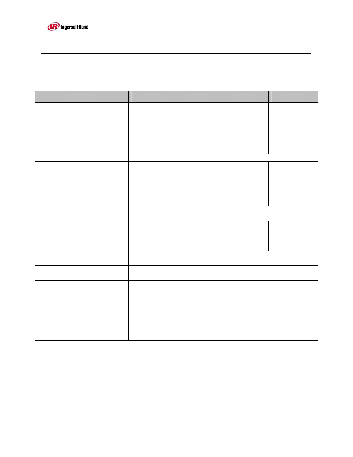
1.4.5 Technical data sheet
MODEL HC-54 HC-69 HC-85 HC-103
Flow:
(SCFM) @ 100 PSIG
100°F Drying Temperature
(m3/hr) @ 6.89Bar(g)
4814
8179
6093
10352
7522
12780
37.8°C Drying Temperature
Vessel OD 48”
121.9 cm
54”
137.2 cm
60”
152.4 cm
Desiccant type IR Activated Alumina
Desiccant / Vessel 3572 lbs
1620 kgs
4521 lbs
2051 kgs
5581 lbs
2531 kgs
Inlet connection 6 FLG 6 FLG 8 FLG 8 FLG
Outlet connection 6 FLG 6 FLG 8 FLG 8 FLG
Afterfilter
(* Option)
AF-7200
or HAF-7200*
AF-7200
or HAF-7200*
AF-7200
or HAF-7200*
or HAF-10000*
Voltage 115/1/60 Standard
Consult Factory for other voltages
Cooling Water 143 GPM
541 LPM
Stripping Flow 96 SCFM
163 m3/hr
138 GPM
572 LPM
122 SCFM
207 m3/hr
172 GPM
651 LPM
150 SCFM
255 m3/hr
Cycle time 8 Hour NEMA Cycle –
4 Hours drying/ 4 Hours Regeneration
Outlet Dew Point Variable
DPDS Control Adjustable
High Humidity Alarm Adjustable
Pressure Switch Setpoint 10 PSI Fail to Shift 60 PSI Initiate Cooling
.7 Bar Fail to Shift 4 Bar Initiate Cooling
Cooler outlet high temperature
alarm
Low regeneration temperature
105F
40.6°C
Adjustable
alarm
Process flow Downward Regeneration / Upward Drying
9101
15463
66”
167.6 cm
6753 lbs
3063 kgs
AF-10000
208 GPM
787 LPM
182 SCFM
309 m3/hr
Reference IR - 222 Rev 3
Page 18 10/17/2013
USER MANUAL
Series HC
SECTION 1: (Continued)
1.4.5 Technical data sheet
MODEL HC-122 HC-143 HC-166
Flow:
(SCFM) @ 100 PSIG
100°F Drying Temperature
(m3/hr) @ 6.89Bar(g)
10832
18404
12712
21598
37.8°C Drying Temperature
Vessel OD 72”
182.9 cm
78”
198.12 cm
Desiccant type IR Activated Alumina
Desiccant / Vessel 8037 lbs
3646 kgs
9432 lbs
4278 kgs
Inlet connection 8 FLG 8 FLG 10 FLG
Outlet connection 8 FLG 8 FLG 10 FLG
Afterfilter
(* Option)
AF-16000
or HAF-16000*
AF-16000
or HAF-16000*
or HAF-16000*
Voltage 115/1/60 Standard
Consult Factory for other voltages
Cooling Water 247 GPM
935 LPM
Stripping Flow 217 SCFM
627 m3/hr
289 GPM
1094 LPM
254 SCFM
734 m3/hr
8 Hour NEMA Cycle –
4 Hours drying/ 4 Hours Regeneration
Outlet Dew Point Variable
DPDS Control Adjustable
High Humidity Alarm Adjustable
Pressure Switch Setpoint 10 PSI Fail to Shift 60 PSI Initiate Cooling
.7 Bar Fail to Shift 4 Bar Initiate Cooling
Cooler outlet high temperature
alarm
Low regeneration temperature
105F
40.6°C
Adjustable
alarm
Process flow Downward Regeneration / Upward Drying
14742
25047
84”
213.36 cm
10939 lbs
4962 kgs
AF-16000
335 GPM
1268 LPM
295 SCFM
851 m3/hr
Reference IR - 222 Rev 3
Page 19 10/17/2013
USER MANUAL
Series HC
SECTION 1: (Continued)
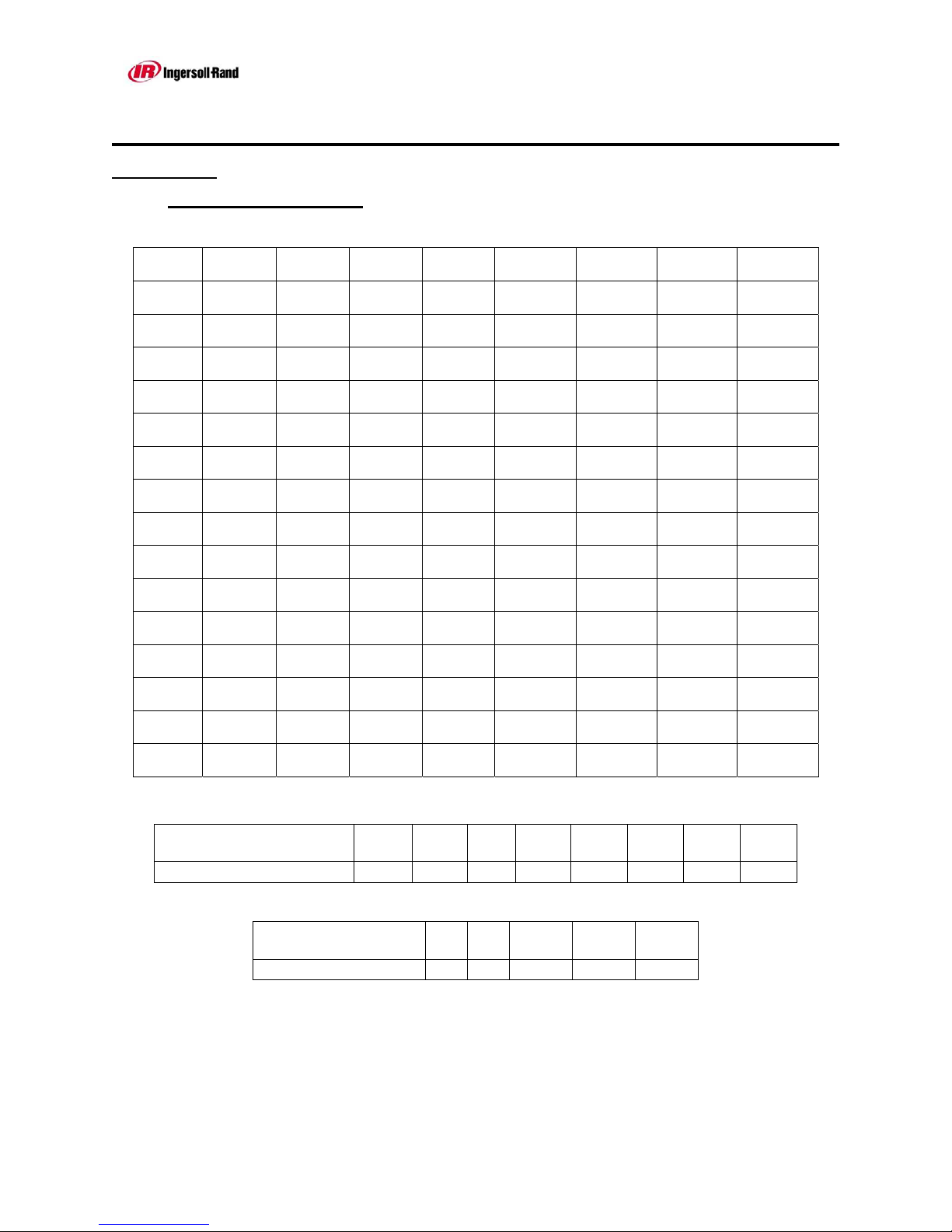
1.4.6 Dryer Flow Capacities
Model Selection Chart:
MODEL
HC-3
HC-6
HC-7
HC-9
HC-14
HC-21
HC-30
HC-41
HC- 54
HC-69
HC-85
HC-103
HC-122
HC-143
HC-166
PSI:
Bar:
SCFM:
Nm3/h:
SCFM:
Nm3/h:
SCFM:
Nm3/h:
SCFM:
Nm3/h:
SCFM:
Nm3/h:
SCFM:
Nm3/h:
SCFM:
Nm3/h:
SCFM:
Nm3/h:
SCFM:
Nm3/h:
SCFM:
Nm3/h:
SCFM:
Nm3/h:
SCFM:
Nm3/h:
SCFM:
Nm3/h:
SCFM:
Nm3/h:
SCFM:
Nm3/h:
Minimum Inlet Pressure
Correction Factor
CORRECTION FACTOR FOR COOLING WATER TEMPERATURE
85
5.86
262
421
465
748
588
945
726
1167
1046
1682
1634
2627
2353
3783
3203
5150
4183
6725
5295
8513
6537
10510
7909
12716
9413
15134
11047
17761
12812
20598
Note: Maximum operating pressure is 150 PSIG (10.34 Bar);
higher pressures available as an option. Consult factory.
90
6.2
274
441
486
781
615
989
760
1222
1094
1759
1709
2748
2462
3958
3351
5388
4376
7035
5539
8905
6837
10992
8273
13301
9846
15830
11555
18577
13401
21545
PSIG:
Bar:
95
6.55
287
461
509
818
645
1037
796
1280
1146
1842
1790
2878
2578
4145
3509
5642
4583
7368
5801
9326
7161
11513
8664
13929
10312
16579
12102
19457
14035
22565
85
5.86
90
6.2
100
6.9
301
484
535
860
677
1088
836
1344
1204
1936
1880
3023
2708
4354
3686
5926
4814
7740
6093
9796
7522
12093
9101
14632
10832
17415
12712
20438
14743
23703
95
6.55
105
7.24
313
503
557
896
705
1133
870
1399
1253
2014
1957
3146
2819
4532
3837
6169
5011
8056
6343
10198
7830
12589
9474
15232
11276
18129
13233
21275
15347
24674
100
6.9
105
7.24
1.15 1.1 1.05 1 .96 .92 .88
110
7.58
327
526
581
934
735
1182
908
1460
1308
2103
2042
3283
2941
4728
4003
6436
5228
8405
6617
10638
8169
13134
9884
15891
11764
18913
13805
22195
16011
25741
110
7.58
115
7.93
342
550
608
978
769
1236
950
1527
1368
2199
2136
3434
3076
4945
4187
6732
5469
8793
6922
11129
8545
13738
10339
16622
12305
19783
14441
23217
16748
26926
115
7.93
Temperature
Correction Factor
To correct for a cooling water temperature other than 85F, or an operating pressure other than
100 psig, multiply dryer capacity by the correction factors listed above.
Example: To size for an inlet flow of 2208 m^3/hr @ 6.2 Bar, using 32C cooling water:
Multiply 2208 * (1.1) * (1.2) = 2914 Use Model HC-21
Reference IR - 222 Rev 3
Page 20 10/17/2013
°F
ºC 7524
.85 .9 1.0 1.2
80
27
85
29
90
32

USER MANUAL
Series HC
SECTION 1: (Continued)
1.4.7 Transport
After the adsorption dryer has been delivered, it must be checked for damage that
may have occurred during transport. The Transport Company must be informed to
register any damage. Shipping damage is not covered by any warranty.
1.4.8 Storage
If the adsorption dryer is to be stored for a prolonged period of time, it should be
stored in a dry place, preferably indoors; protected from the elements including
freezing or extremely warm temperatures.
1.4.9 Use of a pre and afterfilter
Use of a prefilter is not necessary with a heat-of-compression dryer. An afterfilter
should be provided to prevent desiccant dust from migrating downstream.
Reference IR - 222 Rev 3
Page 21 10/17/2013

USER MANUAL
Series HC
Prior to installation and start-up of this dryer,
please read and implement this section.
SECTION 2
INSTALLATION
Reference IR - 222 Rev 3
Page 22 10/17/2013

USER MANUAL
Series HC
SECTION 2:
INSTALLATION
2.1 SET-UP AND INSTALLATION
Once at the installation location, the adsorption dryers of the series HC-3 – HC-239,
which are supplied with a base frame, must be positioned so that all sides are easily
accessible. Should vibrations occur on the installation location, the adsorption dryer
is to be placed onto vibration dampeners.
Since the adsorption dryer has already been completely wired at our factory, the
customer only has to connect the power supply cable to the terminal strip according
to the supplied wiring diagrams.
Advice
Should you still have questions regarding installation, you can request
installation blueprints separately from IInnggeerrssoollll--RRaanndd Davidson NC.
Warning!
Use the appropriate, load-rated lifting equipment
and observe safe lifting procedures during all
operations of installation.
The equipment should be unloaded as close as
possible to the installation site to minimize any
chances of equipment damage.
Reference IR - 222 Rev 3
Page 23 10/17/2013

USER MANUAL
Series HC
SECTION 2: (Continued)
2.1.1 Mechanical installation
The equipment should be located in an area as practically possible with
adequate clearances for service. An overhead clearance of not less than three
feet above each adsorber tower is required for loading of the desiccant. Access
clearance of three feet in front of the control panel should be provided. Insulate
the pipe between the compressor and dryer to minimize heat loss. Remove all
protective shipping crates, flange covers, etc.
Utilizing the mounting holes provided on the skid, anchor the IInnggeerrssoollll--RRaanndd type
HC Dryer to a solid, level foundation designed to support the dryer.
Do not hydrostatically test the pressure vessels. All HC dryers’ pressure vessels
are hydrostatically tested at 1.3 times the design pressure after fabrication and
before assembly.
Desiccant is shipped loose (HC-41 and above) and must be installed. Refer to
Section 4.2 for installation of desiccant.
If the equipment is installed in a high traffic area, protective barriers may be
required to prevent possible damage of equipment and to prevent contact with
hot surfaces.
Because of vibration during shipping, some tube fittings may have loosened;
therefore, inspect all connections and tighten if required. Also, flange
connections may have loosened; therefore tighten all flange bolts.
Ensure that the inlet and outlet connections to and from the IInnggeerrssoollll--RRaanndd type
HC Dryer are made using the correct rated fittings and piping to meet the design
conditions.
System isolation and by-pass valves should be installed. If not supplied as part
of the equipment package by IInnggeerrssoollll--RRaanndd, they should be supplied and installed
by others. It must be verified that these exist, so that future servicing of the Dryer
System may take place.
Full flow relief valves to protect the system from over-pressure must be provided
by others in accordance with local regulations.
The purge exhaust connection on the HC larger dryers may be connected to a
vent header. To ensure satisfactory regeneration of the desiccant chambers is
achieved, the purge exhaust piping should be sized as follows to prevent "back
pressure" build up.
Installed length of exhaust pipe Pipe size required
Up to 10 ft (3.048 m) Same size as the dryer exhaust
Up to 25 ft (7.62 m) One size larger than dryer exhaust
Up to 50 ft (15.24 m) Two sizes larger than dryer exhaust
Up to 100 ft (30.48 m) Three sizes larger than dryer exhaust
Reference IR - 222 Rev 3
Page 24 10/17/2013

USER MANUAL
Series HC
SECTION 2: (Continued)
2.1.2 Preventative Maintenance Prior to Start-up
2.1.2.1 All air dryers are test ed at the factory for leak-tight joints and tightness of bolts;
however, during shipment, some bolts may vibrate loose. We have no control
over the handling our compressed air systems receive after leaving our factory.
To prevent costly problems at start-up and operation, all bolts should be
checked for tightness prior to system pressurization. This will assure gasket life
as well as prevent possible gasket blowout. Gasket joints should be bubble
tested after four or five complete cycles of the dryer, to ensure gaskets are
sealed. Any loose joints will need to be re-tightened and re-tested for leaks.
Following is a comprehensive procedure for tightening all pressurized gasketed
joints. If the dryer includes manual butterfly valves, valves must be totally
closed before re-torquing bolts.
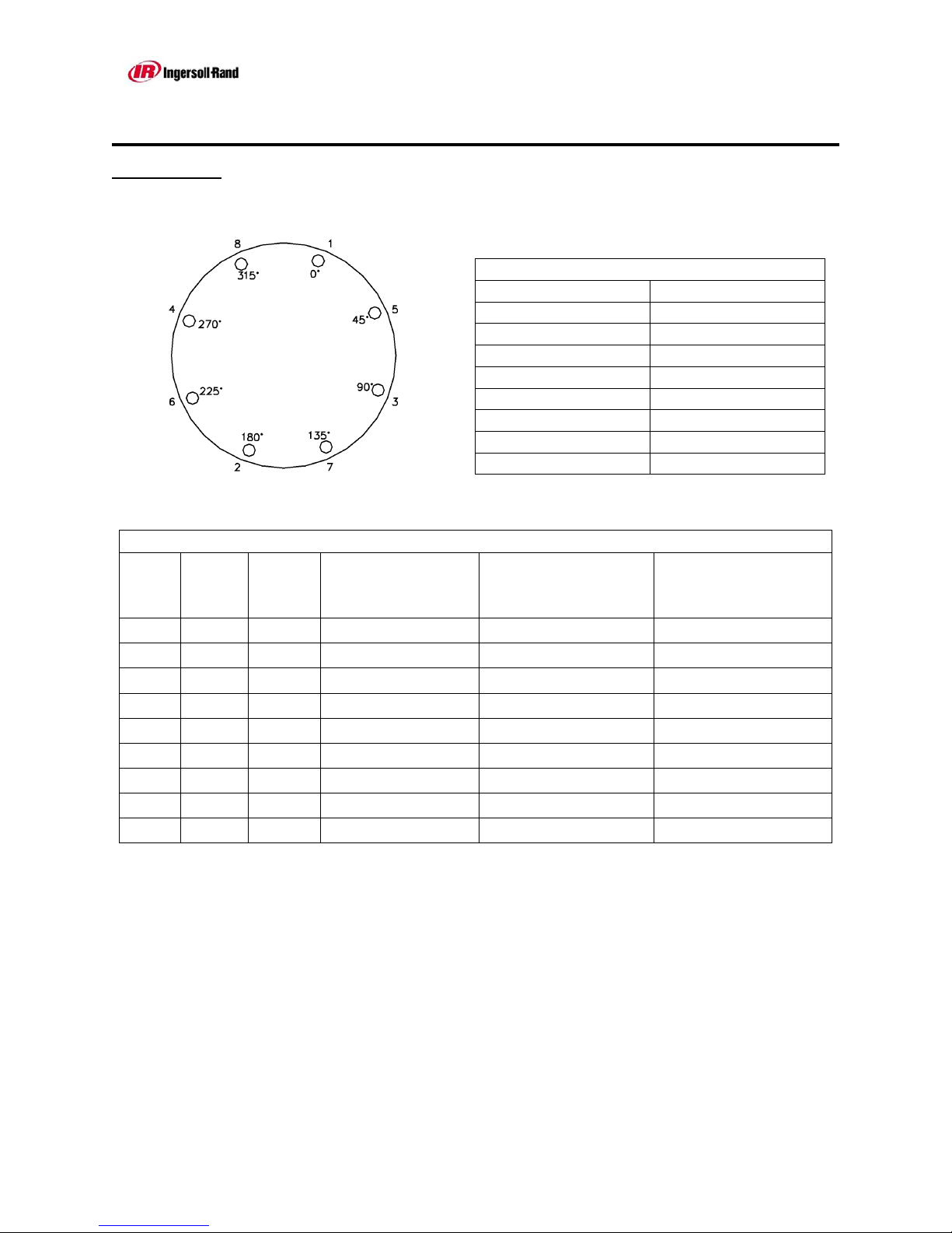
2.1.2.2 TIGHTEN BOLTS IN SEQUENTIAL ORDER (i.e. 0 - 180, 90 - 270, 45 -
225, and 135 - 315) until final torque is reached.
2.1.2.3 Use ROTATIONAL TIGHTENING until all bolts are stable at final torque level.
(Two complete times around is usually required.)
Reference IR - 222 Rev 3
Page 25 10/17/2013
USER MANUAL
Series HC
SECTION 2: (Continued)
FLANGE BOLT
TORQUE PROCEDURE
8 BOLTS
SEQUENTIAL ORDER ROTATIONAL ORDER
1-2 1
3-4 5
5-6 3
7-8 7
2
6
4
8
FLANGE BOLT TIGHTENING TORQUES
150# FLANGE RATING
RECOMMENDED
TORQUE / BOLT
(FT. LBS.)
MINIMUM TORQUE
(FT. LBS.)
MAXIMUM TORQUE
(FT. LBS.)
SIZE
BOLT
QTY.
BOLT
SIZE
1" 4 ½" 16 14 64
1 ½" 4 ½" 32 28 64
2" 4 5/8" 64 56 128
3" 4 5/8" 110 96 128
4" 8 5/8" 78 68 128
6" 8 ¾" 148 129 230
8" 8 ¾" 201 175 230
10" 12 7/8" 191 166 372
12" 12 7/8" 254 221 372
Based on 1/16" gasket material.
If other than 150# flange rating, consult Ingersoll-Rand.
NOTE: We regret any inconvenience this may cause; however, we feel this preventative
procedure will save time and money in the long run. Failure to follow this procedure
may result in premature gasket failure which is not covered by warranty.
Reference IR - 222 Rev 3
Page 26 10/17/2013

USER MANUAL
Series HC
SECTION 2: (Continued)
2.1.3 Filter installation
Series HC dryers are shipped with the afterfilter loose or with the filter skid
mounted on a separate steel frame. The following installation applies to all models
that are shipped with filters loose.
2.1.3.1 Afterfilter Installation
Mount afterfilter in such a way as to allow clearance for the element
installation and removal.
The filter must be piped so that the correct flow direction indicated on the filter
is followed.
Ensure that all piping and valves are equivalent or larger in size to the dryer
inlet connection.
2.1.3.2 Filter Skid with 3-Valve Bypass Installation
Filters skid should be located as close to dryer as possible. Use the skid bolt
holes to secure the assembly.
Ensure that the skid is located such that the 3-valve bypass will bypass the
dryer and filters when in use.
Check the flow direction of each filter to ensure the after filter is connected to
the outlet pipe of the dryer.
Connect the filter skid piping and dryer skid piping using materials and
fabrication procedures that are suitable for compressed air pressure piping. All
flanges are ANSI B16.5 Class 150 Raised Face flanges.
2.1.4 Electrical installation
Connect the dryer to a correctly sized power supply. The dryer requires a
115V 60 cycle connection. A disconnect switch is not provided with the dryer
and must be supplied by end user in accordance with the recognized electrical
codes.
Ground the frame of the dryer in accordance with the recognized electrical
codes.
It is recommended that the common alarm relay, located in the dryer control
panel, be connected to the control room or operator station so that an
immediate response to the dryer alarm may be given when required.
Reference IR - 222 Rev 3
Page 27 10/17/2013

USER MANUAL
Series HC
Prior to installation and start-up of this dryer,
please read and implement this section.
SECTION 3
START-UP & OPERATION
Reference IR - 222 Rev 3
Page 28 10/17/2013

USER MANUAL
Series HC
SECTION 3:
3.1 START UP
START UP AND OPERATION
Attention!
All pipes and wire connections are to be tightened!
Furthermore, before start-up:
The pipes must be checked for the presence of scale,
abraded material from the threading, or other similar
impurities.
All shut off valves on the adsorption dryer, afterfilter
and on the bypass line should be closed.
The ambient temperature must not be less than 33°F
(0.56°C).
Breakdowns resulting from faulty installation do not fall under IInnggeerrssoollll--RRaanndd's
warranty obligation.
3.1.1 Pressurizing dryer
Prior to pressurizing the IInnggeerrssoollll--RRaanndd Series HC Dryer system, verify the
following:
- Dryer On – Off switch is in the off position.
- System outlet block valve is closed.
- Cooling water is turned on to the aftercooler.
Slightly open the inlet isolation valve slowly admitting compressed air to the
system. When full system operating pressure has been reached all connections
should be soap bubble tested for leaks. Any leaks should be repaired and
retested prior to placing the equipment in service. If some gas other than the
process air will be used for leak testing, consult Ingersoll-Rand for its
compatibility with system components before proceeding. Fully open the inlet
isolation valve.
When the system is filled with process air, is leak tight and start-up is completed,
then slowly open the system outlet valve to pressurize the downstream piping.
During the procedure, ensure that the dryer system pressure does not fall below
95% of its reading prior to opening the system outlet valve. This will protect the
equipment internal components (i.e. filter elements, desiccant) from gas
velocities above design conditions.
Reference IR - 222 Rev 3
Page 29 10/17/2013

USER MANUAL
Series HC
SECTION 3: (Continued)
3.1.1 Pressurizing dryer (Continued)
When pressurizing is complete then fully open the system outlet valve to place
the equipment in service.
Verify the system inlet pressure and temperature are at the design operating
levels.
Please note that excessive flows or rapid change in pressure may cause
damage to the air dryer skid. Every time there is no line pressure, the
dryer must be valved out and brought up to line pressure slowly.
The dryer should be carefully monitored during the first few hours of operation
to check for malfunction.
Protect the dryer from overloads. The dryer can become overloaded, if:
inlet flow is too high
temperature of the air at the discharge of the aftercooler is too high
minimum operating pressure is too low
temperature of the air at the discharge of the compressor is too low
check Specifications in Section 6 for proper operating conditions
3.2 OPERATOR INTERFACE
NOTE: Reference Section 7 (Auxiliary Manuals) for the operational instructions
specific to the operator interface purchased.
Also in Section 7 can be found the operational instructions for the
optional dew point demand system, if installed on this dryer.
Reference IR - 222 Rev 3
Page 30 10/17/2013
 Loading...