

Page 1
OPERATOR’S
MANUAL
H2XXXX-XXX-X
INCLUDING: APPLICATION, LUBRICATION, INSTALLATION & SERVICE
H SERIES VALVES
RELEASED: 11-20-87
REVISED: 1-26-01
(REV.
A)
READ THIS MANUAL CAREFULL
OPERA
It
is the responsibility of the employer to place this information in the hands of the operator
TING OR SER
VICING THIS EQUIPMENT
Y BEFORE INST
ALLING,
.
. Keep for future reference.
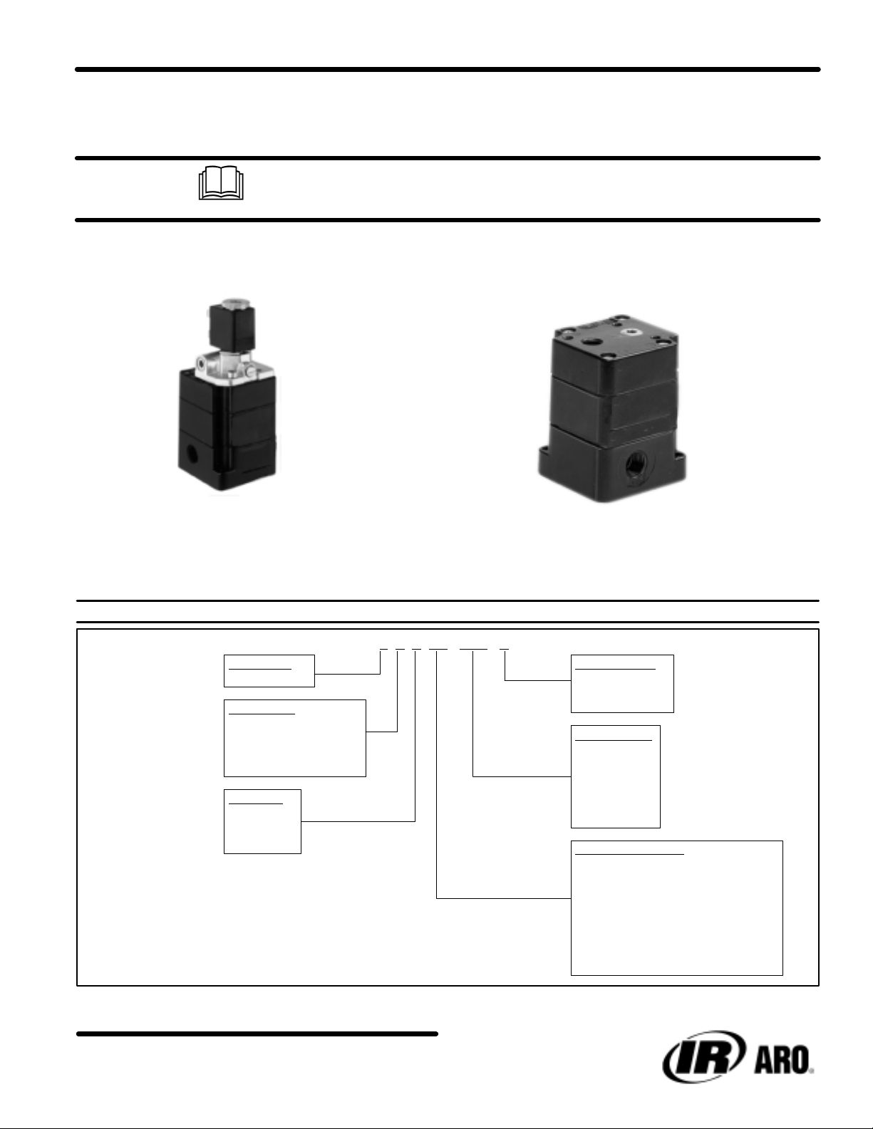
MODEL
VALVE TYPE
2 Ć 2 Position
BODY STYLE
1 Ć 4 Way Side Ported
4 Ć 4 Way Bottom Ported
5 Ć 3 Way Side Ported
8 Ć 3 Way Bottom Ported
PORT SIZE
2 Ć 1/4" NPT
3 Ć 3/8" NPT
4 Ć 1/2" NPT
DESCRIPTION CHART
H2X X XX Ć XXX ĆX
CURRENT TYPE
AĆAC
DĆDC
N Ć No Coil
COIL VOLTAGE
000 Ć No Coil
005 Ć 5 V
012 Ć12V
024 Ć24V
120 Ć 120 V
240 Ć 240 V
ACTUATOR / RETURN
BD Ć Bleed / Bleed (page 5)
KD Ć Solenoid / Solenoid (page 8)
PA Ć Pilot / Internal Pilot (page 5)
PD Ć Pilot / Pilot (page 5)
PS Ć Pilot / Spring (page 3)
SA Ć Solenoid / Internal Pilot (page 6)
SD Ć Solenoid / Solenoid (page 7)
SS Ć Solenoid / Spring (page 4)
INGERSOLL-RAND COMPANY
P.O. BOX 151 D ONE ARO CENTER D BRYAN, OHIO 43506Ć0151
&
(419) 636-4242 D F
AX (419) 633-1674
E2001 D PRINTED IN U.S.A.
Page 2

Warnings
and Cautions
APPLICATION
WARNINGS:
1. ARO
2. When any ARO valve is used in any type application, safe-
3. ARO
valves are designed for use only in industrial
(air) and / or vacuum systems applications and are NOT to be
used
for individual consumer use, application or service.
guards
must be provided to insure against bodily injury for the
operator
ate
tems and / or brake systems on power presses or similar
equipment.
uses.
and / or other persons in the immediate area.
valves are NOT to be used as a safety device or to oper
and /
or control the operation of full revolution clutch sys
ARO valves are not designed or intended for such
pneumatic
LUBRICATION
Valve components are lubricated at the time of assembly at the
factory
and
can normally be operated without air line lubrication to
an approximate life of twenty million cycles, depending on application.
junction
ing oils used are compatible with the valve seals and are of
sufficient viscosity to assure adequate lubrication. Aro recommends
and
use of compound oils containing graphite fillers, extremely low
viscosities and other non-fluidic lubricants. RECOMMENDED:
Aro
If air line cylinders or other air line devices, used in con
with ARO valves, require lubrication, be sure the
an oil lubricant
an aniline point above 200_ F
29665 air line lubricator oil is
INSTALLATION
with a viscosity of 100 - 200 SUS at 100_ F
. Aro does not recommend the
available in one quart containers.
AND SER
VICE
lubricat
the limits set forth in the specifications for a particular valve
model.
5. When a manually operated (actuated) valve is used or
installed into a system, provisions must be made to prevent
the
valve from being accidentally operated (actuated), which
may in turn cause bodily injury or otherwise cause a hazard
ous or dangerous condition
6. Damaged air pressure hoses
tions,
can cause accidental valve operation (actuation), which
may
in turn cause
-
-
-
-
ous or dangerous condition. KEEP ALL HOSES, ELECTRICAL
CLASS
7.
ARO 2-POSITION, 4-WAY VALVES:
the
is applied
be an open flow path of air from the inlet to one
outlets.
installed into the system so all air pressure can be
from valve or system before performing service or maintenance
8. ARO
ARO valve, either a double
pressure
tor has shifted the valve, air pressure applied at the inlet
port(s) will flow thru the valve to one of the two outlet
When
matically
closed center or open center type and will reveal the following
characteristics
WIRING,
OPERA
2-positions this type of ARO valve
A method to exhaust this trapped air pressure must be
to valve.
3-POSITION,
the valve is not in a shifted position, the valve will auto
TING CONDITION.
to
the inlet port(s) of these valves, there will always
or manual operation is used. When the valve
move to a center position. ARO valves can be either
when the valve is in the center position:
bodily injury or otherwise cause a hazard
FITTINGS AND CONNECTIONS IN FIRST
4-W
or electrical wiring, or connec
Regardless of which of
is in, when air pressure
AY VALVES: To actuate this type of
solenoid, double remote air pilot
of the valve
removed
actua
ports.
-
-
-
-
-
WARNINGS:
1. Shut
2. Shut off and disconnect electrical supply to system before
3.
4. DO
of
f, disconnect and exhaust air pressure from system be
fore
installing or performing service to any ARO valve.
installing
Allow only persons with a thorough understanding
eration
ticular
with other components of the system to install or perform
maintenance or service to any ARO valve or other components
or performing service to any ARO valve.
of the op
and application of all ARO valves being used in a par
system and how the ARO
of the system.
NOT subject any ARO valve to any condition that exceeds
valve(s) relate to and interact
a. OPEN
-
-
-
b. CLOSED
CENTER V
the
center position, the
outlet ports are open to the exhaust port(s) of the valve.
With this type valve, in the center position, air pressure
not present at either outlet port. Do not use this type ARO
valve if exhausting the air pressure from the valve will
cause
hazardous or dangerous condition.
CENTER V
center position, all inlet, outlet and exhaust ports are
blocked.
blocked at the port(s) may cause a hazardous or dangerous
ing
trol
positive stop on the holding device.
Do not use this
condition in the application, installation and / or servic
of an ARO valve. These valves must not be used to con
load holding
ALVES:
devices without an additional mechanical
When this type ARO valve is
inlet port(s) is blocked and the two
ALVES: When this type valve is in the
type valve if having the air pressure
in
is
-
-
H Series Valves2OF12
Page 3
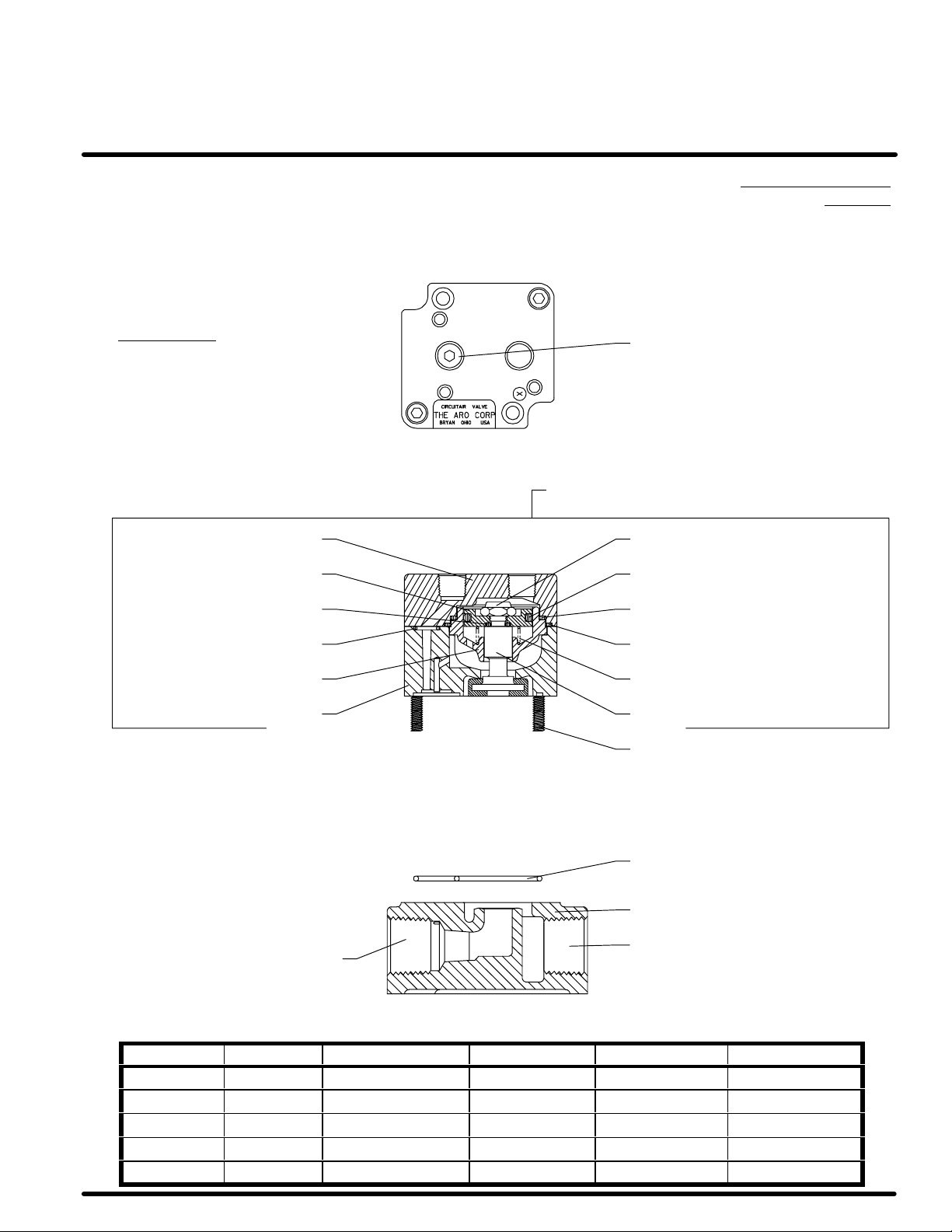
PARTS LIST
SERIES H POPPET VALVES
SUB-BASE MOUNTED
(1/4, 3/8 AND 1/2 N.P.T.F. PIPE PORTS)
3-WAY PILOT, SPRING RETURN
PRESSURE RANGE: 30 - 150 p.s.i. (2.1 - 10.4 bar)
NOT SHOWN
116343 LABEL
n Y195-68-C SCREW (2)
115006 COVER Y109-428 NUT
9020 PISTON
Q Y325-9 “O” RING
1
15016 V
MODELS: H25XPS
H28XPS
118126 PIPE PLUG
ALVE ASSEMBLY
9026 “O” RING Q
Y325-25 “O” RING Q
Q Y325-10 “O” RING
Q 9019 INSERT
115021 BODY
Y325-28 “O” RING Q
30197 SPRING Q
9021 PLUNGER ASSEMBLY Q
Y195-74-C SCREW (2)
Q PARTS
n
INCLUDED IN REP
INCLUDED IN 1
AIR KIT NO. 7102.
15016 VALVE ASSEMBL
Y.
9124 GASKET Q
SUB-BASE (SEE TABLE)
“B” PIPE PLUG (SEE TABLE)
“A” PIPE PLUG (SEE TABLE)
MODEL NO. SUB-BASE PORT LOCATION PORTS (NPTF) PIPE PLUG “A” PIPE PLUG “B”
H252PS 115013-1 SIDE 1/4 ––– –––
H253PS 115013-2 SIDE 3/8 ––– –––
H254PS 115009 SIDE 1/2 ––– –––
H282PS 115017-1 BOTTOM 1/4 Y227-3 Y227-4
H283PS 115017-2 BOTTOM 3/8 Y227-4 Y227-4
H Series Valves
3OF12
Page 4
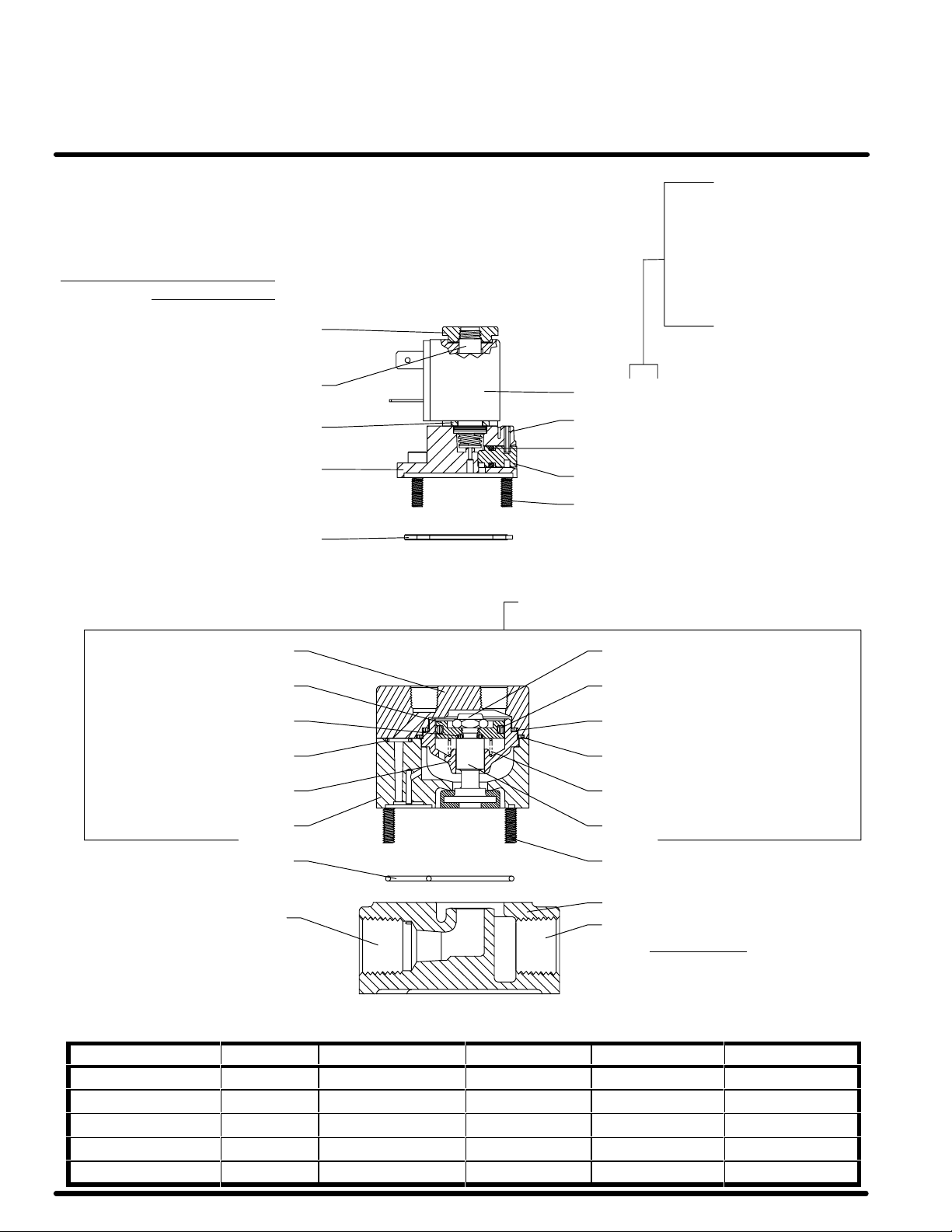
PARTS LIST
SERIES H POPPET VALVES
SUB-BASE MOUNTED
(1/4, 3/8 AND 1/2 N.P.T.F. PIPE PORTS)
3-WAY SOLENOID, SPRING RETURN
PRESSURE RANGE: 30 - 150 p.s.i. (2.1 - 10.4 bar)
MODELS: H25XSS-XXX-X
H28XSS-XXX-X
l 1
19380 NUT
l 1
16507 ARMA
TURE ASS’Y
31 = 12 VAC
33 = 120 VAC
35 = 240 VAC
37 = 5 VDC
38 = 24 VAC / 12 VDC
(DUAL RATING)
39 = 24 VDC / 48 VAC
(DUAL RATING)
116218-XX COIL
l 116506 FLANGE PLATE
l 116495 BASE PLATE
l 116499 GASKET
115006 COVER Y109-428 NUT
9020 PISTON
Q Y325-9 “O” RING
Q Y325-10 “O” RING
Q 9019 INSERT
115021 BODY
1
15016 V
Y178-3 ROLL PIN l
Y325-8 “O” RING l
118590 OVERRIDE PIN
Y195-65-C SCREW (3) l
ALVE ASSEMBLY
9026 “O” RING Q
Y325-25 “O” RING Q
Y325-28 “O” RING Q
30197 SPRING Q
9021 PLUNGER ASSEMBLY Q
Y195-74-C SCREW (2)Q 9124 GASKET
“A” PIPE PLUG (SEE TABLE)
Q PARTS
n
l P
INCLUDED IN REP
INCLUDED IN 1
ARTS INCLUDED IN REP
15016 VALVE ASSEMBL
AIR KIT NO. 7102.
AIR KIT NO. 1
Y.
16572.
“B” PIPE PLUG (SEE TABLE)
NOT SHOWN
116343 LABEL
n Y195-68-C SCREW (2)
l 116346 SCREW (2)
l 118126 PIPE PLUG
MODEL NO. SUB–BASE PORT LOCATION PORTS (NPTF) PIPE PLUG “A” PIPE PLUG “B”
H252SS-XXX-X 115013-1 SIDE 1/4 ––– –––
H253SS-XXX-X 115013-2 SIDE 3/8 ––– –––
H254SS-XXX-X 115009 SIDE 1/2 ––– –––
H282SS-XXX-X 115017-1 BOTTOM 1/4 Y227-3 Y227-4
H283SS-XXX-X 115017-2 BOTTOM 3/8 Y227-4 Y227-4
SUB-BASE (SEE TABLE)
H Series Valves4OF12
Page 5

PARTS LIST
SERIES H POPPET VALVES
SUB-BASE MOUNTED
(1/4, 3/8 AND 1/2 N.P.T.F. PIPE PORTS)
4-WAY PILOT AND DOUBLE BLEED
PRESSURE RANGE: 20 - 150 p.s.i. (1.4 - 10.4 bar)
Q PARTS
n
INCLUDED IN 1
INCLUDED IN REP
15014 VALVE ASSEMBL
118126 PLUG
MODELS: H21XPA
115007 COVER Y109-428 NUT (2)
AIR KIT NO. 7103.
H24XPA
Q 9025 DISC
24130 BUTTON BLEEDER
Y.
ASSEMBLY (2)
MODELS: H21XBD
H24XBD
1
15014 V
9023 GASKET Q
9600 PILOT BLEEDER
ASSEMBLY (2)
MODELS: H21XPD
H24XPD
ALVE ASSEMBLY
Q Y325-25 “O” RING (2)
9020 PISTON (2)
Q Y325-9 “O” RING (2)
Q 9021 PLUNGER ASS'Y (2)
Q 9024 GASKET
NOT SHOWN
116154 LABEL
n Y195-68-C SCREW (2)
MODEL NO. SUB-BASE PORT LOCATION PORTS (NPTF) PIPE PLUG (2)
H212XX 115022-1 SIDE 1/4 –––
H213XX 115022-2 SIDE 3/8 –––
H214XX 115008 SIDE 1/2 –––
H242XX 115029-1 BOTTOM 1/4 Y227-3
H243XX 115029-2 BOTTOM 3/8 Y227-4
9026 “O” RING (2) Q
Y325-28 “O” RING (2) Q
9019 INSERT (2) Q
115015 BODY
Y195-74-C SCREW (3)
SUB-BASE (SEE TABLE)
H Series Valves
5OF12
Page 6

PARTS LIST
SERIES H POPPET VALVES
SUB-BASE MOUNTED
(1/4, 3/8 AND 1/2 N.P.T.F. PIPE PORTS)
4-WAY SOLENOID, INTERNAL PILOT RETURN
PRESSURE RANGE: 25 - 135 p.s.i. (1.7 - 9.3 bar)
MODELS: H21XSA-XXX-X
H24XSA-XXX-X
l 1
19380 NUT
l 1
16507 ARMA
TURE ASS’Y
31 = 12 VAC
33 = 120 VAC
35 = 240 VAC
37 = 5 VDC
38 = 24 VAC / 12 VDC
(DUAL RATING)
39 = 24 VDC / 48 VAC
(DUAL RATING)
116218-XX COIL
l 116506 FLANGE PLATE
l 116495 BASE PLATE
l 116499 GASKET
115007 COVER Y109-428 NUT (2)
Q Y325-25 “O” RING (2)
9020 PISTON (2)
Q Y325-9 “O” RING (2)
Q 9021 PLUNGER ASS'Y (2)
Q 9024 GASKET
Q 9025 DISC
Y178-3 ROLL PIN l
Y325-8 “O” RING l
118590 OVERRIDE PIN
Y195-65-C SCREW (4) l
1
15014 V
9023 GASKET Q
ALVE ASSEMBLY
9026 “O” RING (2) Q
Y325-28 “O” RING (2) Q
9019 INSERT (2) Q
115015 BODY
Y195-74-C SCREW (3)
SUB-BASE (SEE TABLE)
Q PARTS
n
l P
INCLUDED IN REP
INCLUDED IN 1
ARTS INCLUDED IN REP
H212SA-XXX-X 115022-1 SIDE 1/4 –––
H213SA-XXX-X 115022-2 SIDE 3/8 –––
H214SA-XXX-X 115008 SIDE 1/2 –––
H242SA-XXX-X 115029-1 BOTTOM 1/4 Y227-3
H243SA-XXX-X 115029-2 BOTTOM 3/8 Y227-4
NOT SHOWN
116154 LABEL
AIR KIT NO. 7103.
15014 VALVE ASSEMBL
AIR KIT NO. 1
Y.
16572.
n Y195-68-C SCREW (2)
Q Y325-10 “O” RING
l 116346 SCREW (2)
l 118126 PIPE PLUG
MODEL NO. SUB-BASE PORT LOCATION PORTS (NPTF) PIPE PLUG (2)
H Series Valves6OF12
Page 7

PARTS LIST
SERIES H POPPET VALVES
SUB-BASE MOUNTED
(1/4, 3/8 AND 1/2 N.P.T.F. PIPE PORTS)
4-WAY DOUBLE SOLENOID
PRESSURE RANGE: 25 - 135 p.s.i. (1.7 - 9.3 bar)
l 119380 NUT (2)
l 116507 ARMATURE ASS'Y (2)
l 116506 FLANGE PLATE (2)
l Y178-3 ROLL PIN (2)
118590 OVERRIDE PIN (2)
l 116501-2 BASE PLATE
l 116505 GASKET
Q 9025 DISC
116218-XX COIL (2)
Y325-8 “O” RING (2) l
Y195-65-C SCREW (4) l
1
15014 V
9023 GASKET Q
MODELS: H21XSD-XXX-X
H24XSD-XXX-X
31 = 12 VAC
33 = 120 VAC
35 = 240 VAC
37 = 5 VDC
38 = 24 VAC / 12 VDC
(DUAL RATING)
39 = 24 VDC / 48 VAC
(DUAL RATING)
ALVE ASSEMBLY
115007 COVER Y109-428 NUT (2)
Q Y325-25 “O” RING (2)
9020 PISTON (2)
Q Y325-9 “O” RING (2)
Q 9021 PLUNGER ASS'Y (2)
Q 9024 GASKET
Q PARTS
n
l P
INCLUDED IN REP
INCLUDED IN 1
ARTS INCLUDED IN REP
15014 VALVE ASSEMBL
MODEL NO. SUB-BASE PORT LOCATION PORTS (NPTF) PIPE PLUG (2)
H212SD-XXX-X 115022-1 SIDE 1/4 –––
H213SD-XXX-X 115022-2 SIDE 3/8 –––
H214SD-XXX-X 115008 SIDE 1/2 –––
H242SD-XXX-X 115029-1 BOTTOM 1/4 Y227-3
H243SD-XXX-X 115029-2 BOTTOM 3/8 Y227-4
AIR KIT NO. 7103.
Y.
AIR KIT NO. 1
16574.
9026 “O” RING (2) Q
Y325-28 “O” RING (2) Q
9019 INSERT (2) Q
115015 BODY
Y195-74-C SCREW (3)
SUB-BASE (SEE TABLE)
NOT SHOWN
116154 LABEL
n Y195-68-C SCREW (2)
l 116346 SCREW (4)
l 118126 PIPE PLUG
H Series Valves
7OF12
Page 8

PARTS LIST
SERIES H POPPET VALVES
SUB-BASE MOUNTED
(1/4, 3/8 AND 1/2 N.P.T.F. PIPE PORTS)
4-WAY DOUBLE SOLENOID
PRESSURE RANGE: 25 - 135 p.s.i. (1.7 - 9.3 bar)
MODELS: H21XKD-XXX-X
H24XKD-XXX-X
119380 NUT (2)
116507 ARMATURE ASS'Y (2)
116506 FLANGE PLATE (2)
31 = 12 VAC
33 = 120 VAC
35 = 240 VAC
37 = 5 VDC
38 = 24 VAC / 12 VDC
(DUAL RATING)
39 = 24 VDC / 48 VAC
(DUAL RATING)
Y178-3 ROLL PIN (2)
118590 OVERRIDE PIN (2)
116501-1 BASE PLATE
116505 GASKET
115007 COVER Y109-428 NUT (2)
Q Y325-25 “O” RING (2)
9020 PISTON (2)
Q Y325-9 “O” RING (2)
Q 9021 PLUNGER ASS'Y (2)
Q 9024 GASKET
Q 9025 DISC
116218-XX COIL (2)
Y325-8 “O” RING (2)
Y195-65-C SCREW (4)
1
15014 V
9023 GASKET Q
ALVE ASSEMBLY
9026 “O” RING (2) Q
Y325-28 “O” RING (2) Q
9019 INSERT (2) Q
115015 BODY
Y195-74-C SCREW (3)
SUB-BASE (SEE TABLE)
NOT SHOWN
116154 LABEL
n Y195-68-C SCREW (2)
116346 SCREW (4)
118126 PIPE PLUG
MODEL NO. SUB-BASE PORT LOCATION PORTS (NPTF) PIPE PLUG (2)
H212KD-XXX-X 115022-1 SIDE 1/4 –––
H213KD-XXX-X 115022-2 SIDE 3/8 –––
H214KD-XXX-X 115008 SIDE 1/2 –––
H242KD-XXX-X 115029-1 BOTTOM 1/4 Y227-3
H243KD-XXX-X 115029-2 BOTTOM 3/8 Y227-4
Q PARTS
n
INCLUDED IN 1
INCLUDED IN REP
15014 VALVE ASSEMBL
AIR KIT NO. 7103.
Y.
H Series Valves8OF12
Page 9

PARTS LIST
SERIES H POPPET VALVES
SUB-BASE MOUNTED
(1/4, 3/8 AND 1/2 N.P.T.F. PIPE PORTS)
3-WAY MANIFOLD ASSEMBLY
1A THRU 1E
23 4 5
“O” RING TO BLOCK OUTLET IN BASE
OF VALVE, NO PORT IN MANIFOLD.
6 “O” RING FOR SEALING BETWEEN
VALVE AND MANIFOLD PORTS.
NOTE: OUTLET ON VALVE MUST BE USED.
NO OUTLET PORT IN MANIFOLD.
ASSEMBLY
9104-2 9104-3 9104-4 9104-5 9104-6
SYMBOL NO.
1A
1B
1C
1D
1E
2
3 “O” RING Y325-18 6 8 10 12 14
4 MANIFOLD BLOCK 9127 2 3 4 5 6
5
6 “O” RING Y325-18 6 9 12 15 18
DESCRIPTION PART NO. QUANTITY
TIE ROD ASSEMBL
TIE ROD ASSEMBL
TIE ROD ASSEMBL
TIE ROD ASSEMBL
TIE ROD ASSEMBL
END BLOCK
INLET BLOCK
SCREW (NOT SHOWN)
LOCK W
ASHER (NOT SHOWN)
Y 9129-2 2
Y 9129-3 2
Y 9129-4 2
Y 9129-5 2
Y 9129-6 2
9130 1 1 1 1 1
9128 1 1 1 1 1
Y154-57 4 6 8 10 12
Y14-10-C 4 6 8 10 12
NUMBER
INLET
1/2 - 14 N.P.T.
OUTLET
1/2 - 14 N.P.T.
H Series Valves
9OF12
Page 10

PARTS LIST
SERIES H POPPET VALVES
SUB-BASE MOUNTED
(1/4, 3/8 AND 1/2 N.P.T.F. PIPE PORTS)
4-WAY MANIFOLD ASSEMBLY
1342
5A THRU 5E
INLET 1/2 - 14 N.P.T.
6
OUTLET 1/2 - 14 N.P.T.
9007-2 9007-3 9007-4 9007-5 9007-6 9008-2 9008-3 9008-4 9008-5 9008-6
SYMBOL NO.
1
2 “O” RING Y325-18 6 8 10 12 14 6 8 10 12 14
3 MANIFOLD BLOCK 9027 2 3 4 5 6 2 3 4 5 6
4
5A
5B
5C
5D
5E
6
7 “O” RING Y325-18 8 12 16 20 24 8 12 16 20 24
DESCRIPTION PART NO. QUANTITY
INLET BLOCK
END BLOCK
TIE ROD ASSEMBL
TIE ROD ASSEMBL
TIE ROD ASSEMBL
TIE ROD ASSEMBL
TIE ROD ASSEMBL
REDUCING BUSHING
SCREW (NOT SHOWN)
LOCK WASHER (NOT SHOWN) Y14-416-C 4 6 8 10 12 4 6 8 10 12
9028 1 1 1 1 1 1 1 1 1 1
9030 1 1 1 1 1 1 1 1 1 1
Y 9129-2 2 2
Y 9129-3 2 2
Y 9129-4 2 2
Y 9129-5 2 2
Y 9129-6 2 2
Y45-103-C 4 6 8 10 12
Y99-43 4 6 8 10 12 4 6 8 10 12
7 “O” RING FOR SEALING BETWEEN
VALVE AND MANIFOLD PORTS.
ASSEMBLY
NUMBER
H Series Valves10OF12
Page 11

H Series Valves
11 OF 12
Page 12

PN 119999Ć37
H Series Valves12OF12
 Loading...