

Page 1
04578092
P7529
Edition 1
January, 2002
Expert Torque Analyzers
ETA2 and ETA5
OPERATORS MANUAL
©2002 Ingersoll-Rand
P7529_Cover_eng.qxd 8/7/03 8:54 AM Page 1
Page 2
7529_eng.fm Page 1 Wednesday, November 12, 2003 8:57 AM
OPERATORS MANUAL FOR
MODEL ETA2 AND ETA5 ANALYZERS
This ETA Analyzer is used for calibration or data collection of torque tools, power and
hand operated, using external transducer(s). This Analyzer can also be used for joint
development and as a failure analysis instrument (using external transducers).
Ingersoll-Rand is not responsible for customer modification of units for applications on
which Ingersoll-Rand was not consulted.
This symbol is to alert the user and service personnel to the presence of important operating instructions that must be read and understood to prevent personal injury, electrical
shock or damage to the equipment.
IMPORTANT SAFETY INFORMATION ENCLOSED -
SAVE THESE INSTRUCTIONS.
READ AND UNDERSTAND THIS MANUAL BEFORE OPERATING THIS PRODUCT.
IT IS YOUR RESPONSIBILITY TO MAKE THIS SAFETY INFORMATION
AVAILABLE TO OTHERS THAT WILL OPERATE THIS PRODUCT.
FAILURE TO OBSERVE THE FOLLOWING WARNINGS COULD RESULT IN
ELECTRIC SHOCK, FIRE AND/OR SERIOUS PERSONAL INJURY.
04578092
Form P7529
Edition 1
January, 2002
Refer All Communications to the Nearest Ingersoll-Rand
Office or Distributor.
© Ingersoll-Rand Company 2002
Printed in U.S.A.
Page 3

7529_eng.fm Page 2 Wednesday, November 12, 2003 8:57 AM
PLACING ANALYZER IN SERVICE
• Always install, operate, inspect and
maintain this product in accordance
with all applicable standards and
regulations (local, state, country, federal, etc.).
USING THE ANALYZER
• Always wear eye protection when operating or performing maintenance on
this tool.
• Always use Personal Protective Equipment appropriate to the tool used and
material worked. This may include dust
mask or other breathing apparatus,
safety glasses, ear plugs, gloves,
apron, safety shoes, hard hat and other
equipment.
• Keep others at a safe distance from
your work area, or ensure they use
appropriate Personal Protective Equipment.
• This tool is not insulated against electric shock.
• This unit is for indoor use only.
• Store idle units. When not in use, units
should be stored in a dry, high or
locked location, out of the reach of children.
• Power tools can vibrate in use. Vibration, repetitive motions or uncomfortable positions may be harmful to your
hands and arms. Stop using any tool if
discomfort, tingling feeling or pain
occurs. Seek medical advice before
resuming use.
• Keep body stance balanced and firm.
Do not overreach when operating this
tool. Anticipate and be alert for sudden
changes in motion, reaction torques, or
forces during start up and operation.
• Ensure work pieces are secure. Use
clamps or vises to hold work piece
whenever possible.
• Never use a damaged or malfunctioning tool or accessory.
• Keep work area clean, uncluttered,
ventilated and illuminated.
• Do not remove any labels. Replace
any damaged label.
• Maintain unit with care. Keep unit clean
for better and safer performance. Follow instructions for changing accessories. Inspect unit cords periodically and
if damaged, have them repaired by an
authorized service facility.
• Do not operate this product in explosive atmospheres, such as in the presence of flammable liquids, gases or
dust.
• Do not modify this product, safety
devices, or accessories.
• Do not use this product for purposes
other than those recommended.
• Use accessories recommended by
Ingersoll-Rand for your model.
• Don’t abuse the cord. Never use the
cord to pull the plug from an outlet.
Keep cords away from heat, oil, sharp
edges or moving parts. Replace damaged cords immediately.
• Avoid body contact with grounded surfaces such as pipes, metal structures
or other electrical products.
• Stay alert, watch what you are doing
and use common sense when operating this product. Do not use this product while tired or under the influence of
drugs, alcohol, or medication.
• Do not use this product near water or
other liquids.
• Do not attach or place external loads
on any part of the unit.
• Replace battery with the same or equivalent type recommended by the battery
manufacturer. Observe correct polarity
when installing battery. Dispose of
used batteries according to battery
manufacturer’s instructions.
2
Page 4

7529_eng.fm Page 3 Wednesday, November 12, 2003 8:57 AM
CAUTION
• The unit should be checked periodically to ensure that the torque readings
are accurate.
• DO NOT store the unit in relative
humidity above 85%.
• Have the unit calibrated at least once a
year.
• Keep the exterior of the unit clean and
dry.
• Do not drop or abuse the unit.
• Do not allow chemicals such as ace-
tone, benzene, thinner, ketone or
trichloroethylene to come in contact
with the housings, as damage will
result.
• The instrument should not be subjected to vibration or shock.
Ingersoll-Rand Company makes no warranty or implies any warranty or liabilities due to the
misuse or damage resulting from the application of the information supplied by this manual.
Liabilities due to errors in the manual are only limited to replacement of the manual.
Ingersoll-Rand reserves the right to change information contained in this manual or the program without notice at any time.
All programs and themanual are copyrighted and rights reserved. Reproduction is prohibited
without prior permission of Ingersoll-Rand.
The use of other than genuine Ingersoll-Rand replacement parts may result in safety hazards,
decreased tool performance, and increased maintenance, and may invalidate all warranties.
Repairs should be made only by authorized trained personnel. Consult your nearest IngersollRand Authorized Servicenter.
• For calibration or repair, return to:
Ingersoll-Rand
ETA Dept.
510 Hester Dr.
Whitehouse, TN 37188
Ingersoll-Rand IDC
ETA Dept.
Swan Lane, Hindley Green
Nr. Wigan
Lancashire, WN2 4EZ
U.K.
3
Page 5
7529_eng.fm Page 4 Wednesday, November 12, 2003 8:57 AM
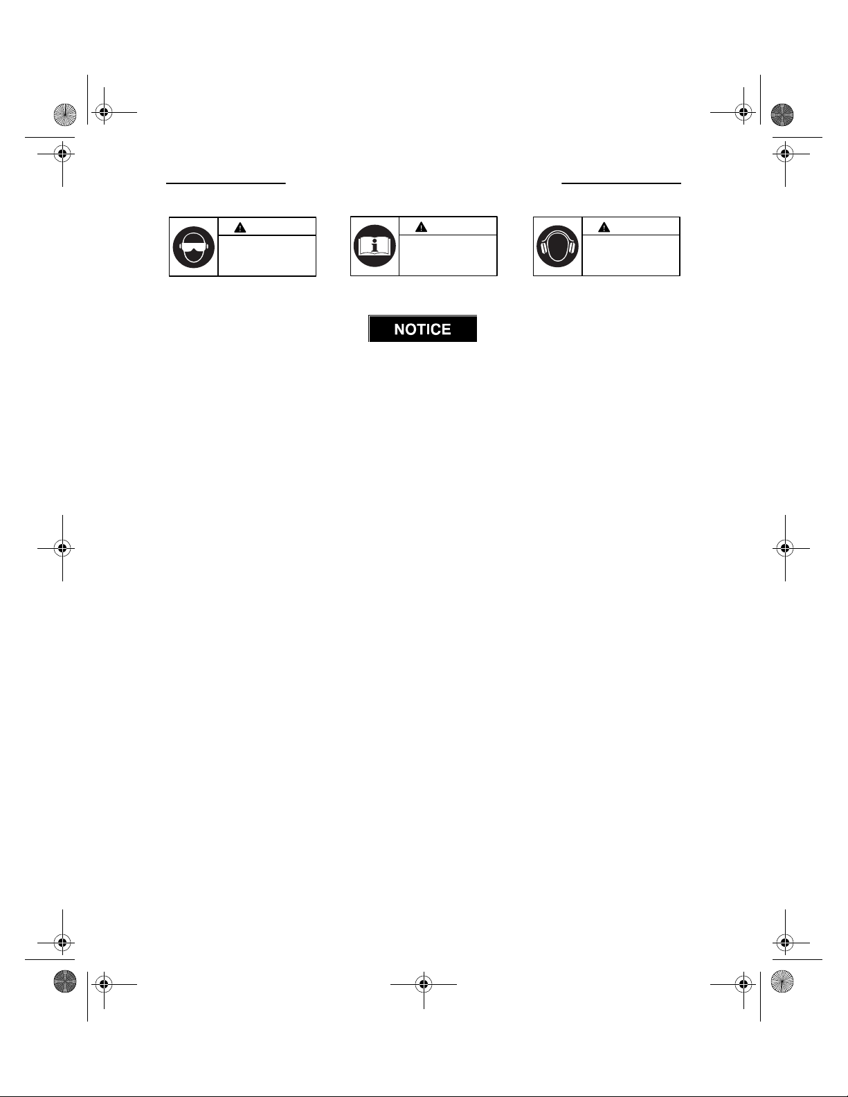
WARNING SYMBOL IDENTIFICATION
WARNING
Always wear eye protection
when operating or performing
maintenance on this tool.
WARNING
Read this manual before
operating tool.
WARNING
Always wear hearing
protection when operating
this tool.
SAVE THESE INSTRUCTIONS. DO NOT DESTROY.
When the life of the tool has expired, it is recommended that the
tool be disassembled, degreased and the parts be separated by material
so that they can be recycled.
4
Page 6
7529_eng.fm Page 5 Wednesday, November 12, 2003 8:57 AM
Table of Contents
ETA Analyzer usage and warnings . . . . . . . . . . . . . . . . . . . . . . . . . 1
Placing Analyzer in Service . . . . . . . . . . . . . . . . . . . . . . . . . . . . . . . 2
Using the Analyzer . . . . . . . . . . . . . . . . . . . . . . . . . . . . . . . . . . . . . . 2
Warning Symbol Identification . . . . . . . . . . . . . . . . . . . . . . . . . . . . . 4
How to use this Manual . . . . . . . . . . . . . . . . . . . . . . . . . . . . . . . . . . 7
Packing List . . . . . . . . . . . . . . . . . . . . . . . . . . . . . . . . . . . . . . . . . . . 8
Care and Storage. . . . . . . . . . . . . . . . . . . . . . . . . . . . . . . . . . . . . . . 9
Battery Charging . . . . . . . . . . . . . . . . . . . . . . . . . . . . . . . . . . . . . . . 9
Edit Transducer File . . . . . . . . . . . . . . . . . . . . . . . . . . . . . . . . . . . . . 10
Barcode read input for characteristic names and comments. . . . . . 13
Measure Mode (Up to 200 readings stored) . . . . . . . . . . . . . . . . . . 14
Measure Mode Circle--Store Option . . . . . . . . . . . . . . . . . . . . . . . . 16
Direct Measure Mode -- ETA5 ONLY . . . . . . . . . . . . . . . . . . . . . . . . 17
To set up a Characteristic -- ETA5 ONLY . . . . . . . . . . . . . . . . . . . . . 19
Direct Characteristic Mode -- ETA5 ONLY . . . . . . . . . . . . . . . . . . . . 21
To Store Data (single characteristic) -- ETA5 ONLY. . . . . . . . . . . . . 23
To set up a Round -- ETA5 ONLY . . . . . . . . . . . . . . . . . . . . . . . . . . 25
To Store Data by Round -- ETA5 ONLY . . . . . . . . . . . . . . . . . . . . . . 26
To set up a Master Round -- ETA5 ONLY . . . . . . . . . . . . . . . . . . . . 27
To Store Data by Master Round. . . . . . . . . . . . . . . . . . . . . . . . . . . . 28
To Display Recorded Data on ETA2 and ETA5 . . . . . . . . . . . . . . . . 29
To View Cp and Cpk . . . . . . . . . . . . . . . . . . . . . . . . . . . . . . . . . . . . 30
French Cp and Cpk . . . . . . . . . . . . . . . . . . . . . . . . . . . . . . . . . . . . . 31
To Erase Stored Data. . . . . . . . . . . . . . . . . . . . . . . . . . . . . . . . . . . . 31
To Erase Stored Data and Setups on ETA5. . . . . . . . . . . . . . . . . . . 32
Page No.
5
Page 7

7529_eng.fm Page 6 Wednesday, November 12, 2003 8:57 AM
Table of Contents (continued)
Printing. . . . . . . . . . . . . . . . . . . . . . . . . . . . . . . . . . . . . . . . . . . . . . . 34
To Print details of Setup or Analysis of Data from ETA5 . . . . . . . . . 34
Printing Data to PC . . . . . . . . . . . . . . . . . . . . . . . . . . . . . . . . . . . . . 39
To Set Date and Time . . . . . . . . . . . . . . . . . . . . . . . . . . . . . . . . . . . 39
To Set Power Off and Backlight Time Delays. . . . . . . . . . . . . . . . . . 40
To Configure Printer Port . . . . . . . . . . . . . . . . . . . . . . . . . . . . . . . . . 40
To Display Software Version Number. . . . . . . . . . . . . . . . . . . . . . . . 41
To Set Password Protection . . . . . . . . . . . . . . . . . . . . . . . . . . . . . . . 41
To Clear Password Protection . . . . . . . . . . . . . . . . . . . . . . . . . . . . . 42
To Perform Software Reset . . . . . . . . . . . . . . . . . . . . . . . . . . . . . . . 43
To Communicate with a PC using PC Comms Software . . . . . . . . . 44
Printout of Readings taken in Measure Mode . . . . . . . . . . . . . . . . . 45
Printout of Setup and Readings taken by Characteristic . . . . . . . . . 46
Printout of Analysis by Characteristic . . . . . . . . . . . . . . . . . . . . . . . 47
Printout of details of all Characteristic setups . . . . . . . . . . . . . . . . . 48
Printout of Round setup . . . . . . . . . . . . . . . . . . . . . . . . . . . . . . . . . . 49
Printout of Readings taken by Characteristic. . . . . . . . . . . . . . . . . . 50
Rotary and Stationary Joint Kits . . . . . . . . . . . . . . . . . . . . . . . . . . . 51
Nominal Joint Stiffnesses - Table. . . . . . . . . . . . . . . . . . . . . . . . . . . 52
Bolt Hole Diagram and Sectional View Diagram . . . . . . . . . . . . . . . 53
Parts List - Table . . . . . . . . . . . . . . . . . . . . . . . . . . . . . . . . . . . . . . . 54
Glossary of Terms . . . . . . . . . . . . . . . . . . . . . . . . . . . . . . . . . . . . . . 55
Error Messages . . . . . . . . . . . . . . . . . . . . . . . . . . . . . . . . . . . . . . . . 58
External Connections. . . . . . . . . . . . . . . . . . . . . . . . . . . . . . . . . . . . 61
Page No.
6
Page 8
7529_eng.fm Page 7 Wednesday, November 12, 2003 8:57 AM
How to use this Manual
This manual is split into sections describing the steps to be taken to configure the
ETA for use in measuring and recording torque values.
There are a number of other parameters which are set from the Software Reset Menu, some of
which are detailed elsewhere in this manual.
Pressing after making a selection will take the user on to the next screen.
Pressing will give the user the option to exit to the Misc menu or continue to edit by
Enter
MENU
pressing .
Screens can be skipped using the and keys.
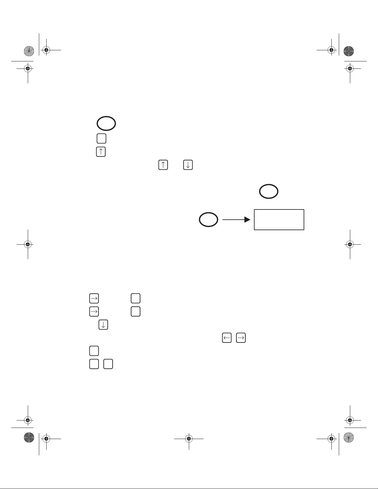
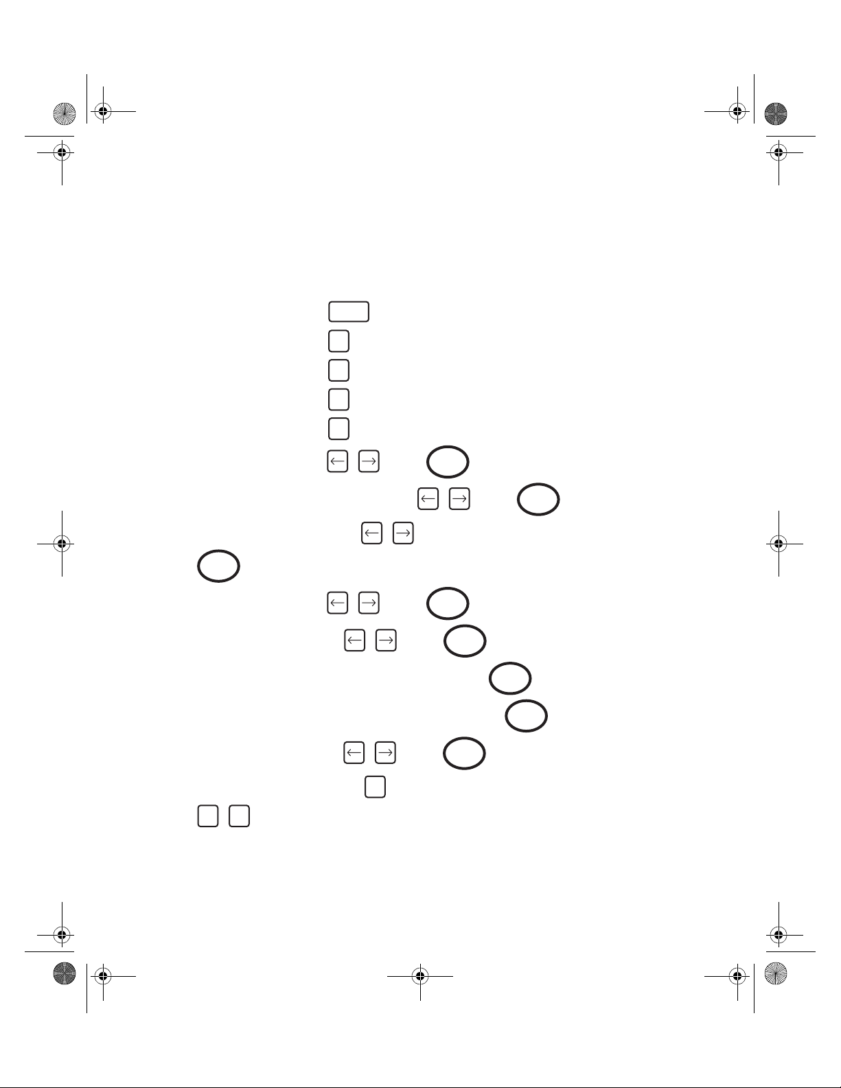
The following method is adopted throughout this manual.
Keys to be pressed will be shown as the key legend in large type: Example
Any special instructions or point to note will be shown as:
Enter
Enter
INSTRUCTION
TO BE
FOLLOWED
Refer to the table of contents to find action to be performed.
Follow instructions for key presses required to carry out required action.
Note: It is possible to change the default primary character on dual function
keys. ie: when text is entered into various fields, it is possible to set
the ETA to default to either the numerals or text as the primary character (the alternate character is selected by pressing the shift key
before typing). To set this:
From main menu:
Press then press (Misc)
6
Press then press (Software Reset)
6
Press the 7 times to access the ‘Shift key’ menu
Select between options 1 ‘Characters’ or 2 ‘Numbers’ using:
MENU
Press Screen will prompt “End of setup”
MENU MENU
Press to return to main menu
7
Page 9
7529_eng.fm Page 8 Wednesday, November 12, 2003 8:57 AM
The following items, except those listed as optional, are included with the ETA unit:
1 x ETA Analyzer . . . . . . . . . . . . . . . . . . . . . . . . . . . . . . . . . . . . . . . . . . . . . . . . . . . . . . . . . ETA
1 x Camera (Neck) Strap . . . . . . . . . . . . . . . . . . . . . . . . . . . . . . . . . . . . . . . . . . . .ETA-STRAP
1 x 9 way D type to 9 way D type PC cable . . . . . . . . . . . . . . . . . . . . . . . . . . . . . . . ETA-PC99
1 x 9 way D type to 25 way D type Printer cable . . . . . . . . . . . . . . . . . . . . . . . . . . . . ETA-P925
1 x 25 way D type to 25 way D type Port Saver . . . . . . . . . . . . . . . . . . . . . . . . . . . . ETA-PS25
1 x Fastcharge Charging Unit (Max. current 1 A) . . . . . . . . . . . . . . . . . . . . . . . . . . . . . ETA-BC
1 x Operators Manual . . . . . . . . . . . . . . . . . . . . . . . . . . . . . . . . . . . . . . . . . . . . . . . . . . . . 7464
1 x Warranty Card . . . . . . . . . . . . . . . . . . . . . . . . . . . . . . . . . . . . . . . . . . . . . . . . . . . . . . 50807
1 x Carrying Case . . . . . . . . . . . . . . . . . . . . . . . . . . . . . . . . . . . . . . . . . . . . . . . . . . .ETA-CASE
1 x Certificate of Calibration . . . . . . . . . . . . . . . . . . . . . . . . . . . . . . . . . . . . . . . . . . . 89937759
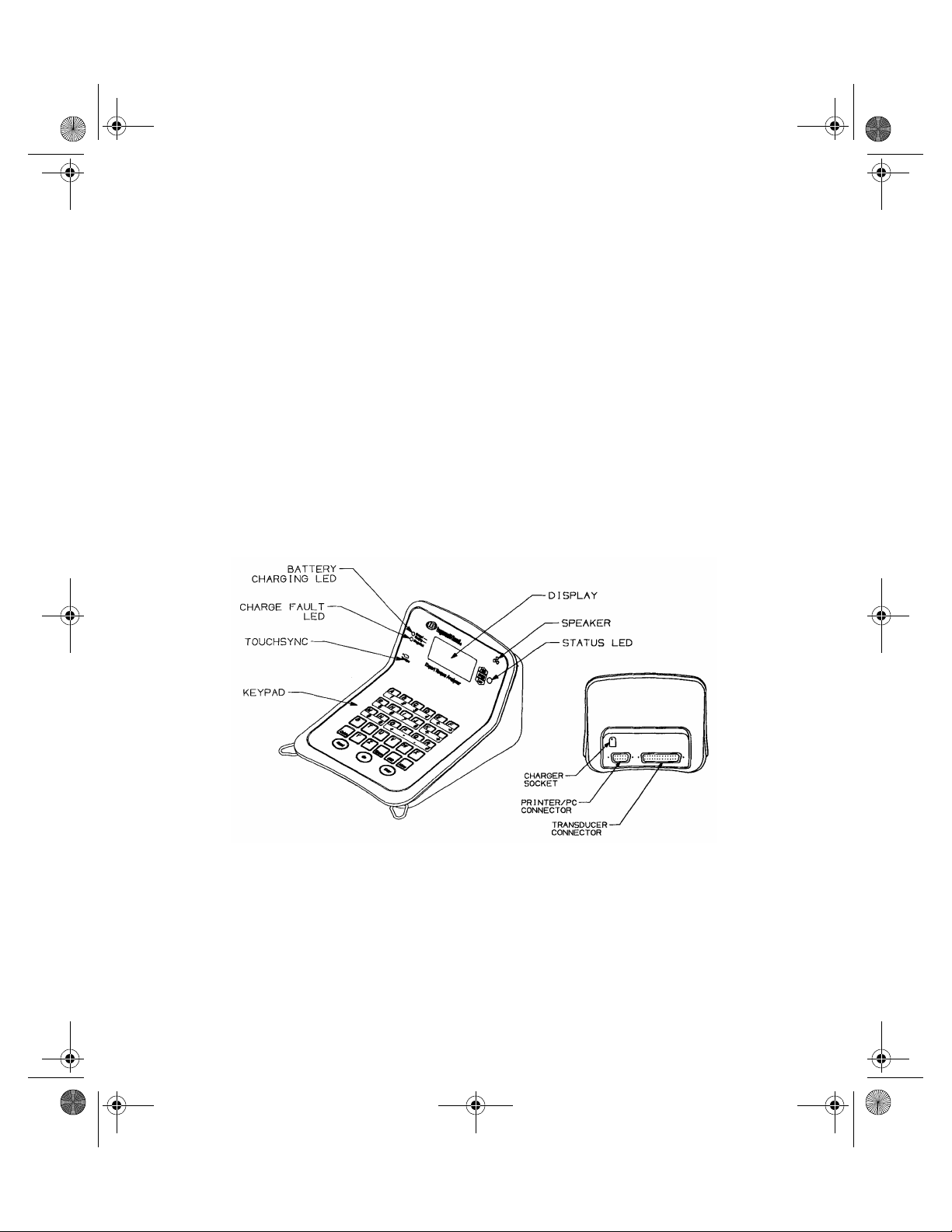
Packing List
(Dwg. TPA1821)
8
Page 10
7529_eng.fm Page 9 Wednesday, November 12, 2003 8:57 AM
Care and Storage
When not in use the unit should be returned
to the supplied carry case.
This unit is designed for indoor use only
Operating temperature range
5-40 degrees C
Storage temperature range
0-50 degrees C
Battery Charging
The batteries in the ETA unit are shipped
fully charged.
In continuous use with a transducer connected, the batteries have a life of at least 8
hours.
With the unit switched off from a 10% charge
state, the batteries will fully discharge in 2550 days. To prevent the loss of all setup
data, the unit has additional battery backup
for the internal memory.
Automatic Power Off
To conserve battery life in use, the unit will
switch off automatically after a predefined
period. Pressing the on key will restore the
unit to the last display prior to powering off.
The membrane keypad may be wiped clean
with a soft damp cloth. The unit is not waterproofed and spillages should be avoided.
THIS UNIT CONTAINS NO USER SERVICEABLE PARTS. ONLY QUALIFIED
SERVICE PERSONNEL SHOULD
REPLACE OR FIT PARTS.
Fast Charge
The ETA’s should only be recharged with the
supplied ETA-BC (Model MPP3OUS12) Battery Charger. ETA’s, are supplied with internal NiMH (Nickel Metal Hydride) batteries.
These are environmentally friendly batteries
presenting no problems for safe disposal
and are capable of sustaining a rapid
recharge. From fully discharged, the unit will
require a charging period of approximately
2.5 hours.
To charge the batteries following a period of
use, connect the supplied charger to the
charging socket on the back of the unit and
plug the charger into a suitable supply. The
green LED will come on to indicate the
machine is charging and will start to flash
when the unit is fully charged. If the red LED
comes on, this means there is a problem
and usually indicates a faulty battery.
The Fast Charge method gives an increase
in the effective life of the charged batteries.
9
Page 11
7529_eng.fm Page 10 Wednesday, November 12, 2003 8:57 AM
Edit Transducer File
Failure to input proper information may result in inaccurate readings.
The following instructions for “Edit Transducer File” must be followed
before any reading or measurements can be taken.
This section may be skipped if you are using an Ingersoll-Rand TSD,
TRD or Crane UTA Series Transducer.
There are 5 types of transducers and inputs
which the ETA will accept.
1. High Output (H/O). These transducers
have an internal amplifier and give an
output signal level of 1-2 Volts.
2. Industry Standard (IS). These trans-
ducers have no internal amplifier. The
exact span or rated torque will be
marked on the transducer nameplate.
The sensitivity of these transducers is 2
mV/V., they are fitted with a 350 Ohm
bridge.
3. Serial. These are digital type transducers and produce an RS232 signal.
4. Keypad (KPD). This is an optional keypad which connects to the ETA.
5. Keyboard (KEY). Keyboard on ETA.
Use of any of the above 5 types of inputs
requires that settings are made in the transducer file before any measurements can
take place. The procedure for entering settings follows.
For ETA5:
At main menu, press (Configure) then
press (Edit Tx)
Screen will show
2
1
Transducer
B (Current set-up)
Complete set-up
The ‘B’ indicates that this is the ‘B’ file in
memory. It is the first of 8 memories (labelled
B to I) reserved for the saving of transducer
set-ups. Your most used transducer setting
should be stored in this memory.
The remaining memories (C to I) may be
accessed by pressing .
Press
Select input type H/O, I/S, SER, KPD or
KEY using ; press .
Enter
Enter
For ETA2:
At main menu, press (Edit Tx)
1
Depending on type of type selected above,
continue set-up by following the appropriate
section.
10
Page 12

7529_eng.fm Page 11 Wednesday, November 12, 2003 8:57 AM
If you have chosen I/S
Select units of measure - inlb, ftlb etc. using press
Type in transducer span- press
Type in mV/V press
Type in Bridge resistance press
Type in Pulses Per Rev (only for angle type) press
Type in Serial Number press
To set-up another transducer press
Enter
Enter
Enter
Enter
Enter
Enter
MENU
Select another memory (B to I) using the keys and press
To return to the main menu, press
MENU
If you have chosen SER
Select location of decimal point using press
Enter
1
Enter
Select Baud Rate, Data Bits, Stop Bits and Parity in the same manner
To set-up another transducer press
MENU
1
Select another memory (B to I) using the keys and press
To return to main menu press
MENU
11
Enter
Page 13
7529_eng.fm Page 12 Wednesday, November 12, 2003 8:57 AM
If you have selected H/O
Select units of measure- inlb, ftlb, etc. using
Note: High Output devices usually produce an output voltage of approximately 1-2 Volts. This
analogue voltage signal will not be exact and may not be linear. If you are using a device that
has a nominal 1Volt output, we suggest that you multiply the span of your transducer by 2.5 to
determine the new span setting.
Type in your new span; press
Type in Serial Number; press
Screen will indicate ‘End of Set-up’; press to return to main menu
Enter
Enter
MENU
Connect your high output device and select measure mode
(refer to instruction sheet for measure mode only)
Use an independent measuring device to apply a torque to the transducer and check the reading on the independent unit against the reading shown on the ETA. It will be necessary to return
to the ‘Edit Tx’ menu option and adjust the span setting until the two readings agree. You may
have to repeat the above procedure several times until your high output transducer is correctly
calibrated.
If you have selected KPD
Select location of decimal point using then press
Select Parity- Odd, Even or Disabled using then press
To set-up another transducer press
MENU
1
Select another memory (B to I) using the keys and press
Enter
Enter
Enter
To return to main menu press
MENU
12
Page 14
7529_eng.fm Page 13 Wednesday, November 12, 2003 8:57 AM
If you have selected KEY
Select location of decimal point using then press
To set-up another transducer press
MENU
1
Select another memory (B to I) using the keys and press
To return to main menu press
MENU
Enter
Enter
Barcode read input for characteristic
names and comments
It is possible to scan a barcode name in ETA5 at certain prompt lines. The input of a barcode is
allowed at the characteristic name prompt in store characteristic, direct characteristic and edit
characteristic modes. In addition it is also possible to scan a barcode in the comment field in
store characteristic only. Edit characteristic and normal store behave in a slightly different manner to direct characteristic. The ETA5 will accept most barcode reading formats, but not all.
General Operational Method for Scanning Bar Code Data
Connect the Bar Code Reader ETA-BAR to the Printer/PC connector at the rear of the ETA5.
Barcode readings can generally be taken at the prompt to input data (Characteristic name or a
comment) when the flashing cursor is on the screen. This can be on a blank line or following a
line of data (an existing characteristic or a comment). When the cursor is flashing, scan the
code with a barcode reader and observe the screen. If the flashing cursor disappears, the code
has been captured - wait a few seconds for the data to appear in the display. If the flashing cursor remains, re-scan the code until it is accepted.
When the data is displayed, press to continue. From this point, follow the instructions
Enter
as for normal data input.
When entering data via the Bar Code Reader into a comment field, make sure you have
reserved enough characters in the comment field to accept the code. If the number of characters scanned in exceeds the number reserved, the ETA5 will beep and refuse to accept the
data. Refer to the instructions on Configuration for more details.
13
Page 15

7529_eng.fm Page 14 Wednesday, November 12, 2003 8:57 AM
Measure Mode (Up to 200 readings stored)
To start, press
MENU
Press
Press (measure)
2
Plug in transducer; press
On
Enter
select proper transducer using
then press
Enter
If using I/S or H/O type transducers
continue with instructions.
If using SER, KPD or KEY, you are now
ready to take measurements.
Select units of measure using ; press
Select Peak, Track, Impulse or ‘Click Dip’ using ; press
Use Peak for direct drive tools, Track for diagnostics, Impulse for pulse tools, and ‘Click Dip’ for
click wrenches.
Select measurement direction using (Right is clockwise. Left is anti-clockwise);
Enter
Enter
press
Select ‘Cycle end Time’ using ; press (normal is 0.5 sec.)
Select frequency response using ; press
Type in Max torque value; press
Type in Min torque value; press
Enter
Enter
Enter
Enter
Enter
14
Page 16
7529_eng.fm Page 15 Wednesday, November 12, 2003 8:57 AM
Type in threshold value; press
Enter
Note: When selecting a threshold torque value the ETA will ignore any
torque that is below this value. You cannot take another reading until
the applied torque falls below this value.
Type in amount of Dip; press
Select Second Parameter using ; press
Enter
Enter
If the setup and transducer has not been changed since the ETA was last used you are now
ready to take torque measurements.
Pressing after taking a series of readings will result in statistical information being dis-
#
played (Range, mean and standard deviation) for the stored readings.
To return to measure mode, press
If you have selected ‘Click Dip’ type in the amount of ‘Dip’ to be sensed; press
#
Enter
Note: 5% of torque for 0 to 100 Nm and 10% of torque for over 100 Nm
generally provide excellent results.
You are now ready to take torque measurements. When finished press
MENU
Note: When taking readings you can change the set-up parameters by
pressing the up arrow
Changing any of the set parameters will result in the ETA prompting to erase all data.
To erase stored readings, press
To return to setup screens, press
Enter
MENU
Example: You have been measuring in a right hand direction and you want to
switch to left hand.
Press the up arrow twice, change from right hand to left hand. Screen will prompt to erase
all data.
Press to erase all stored readings and return to the measure screen.
Enter
15
Page 17
7529_eng.fm Page 16 Wednesday, November 12, 2003 8:57 AM
Printing of stored readings from measure mode
Pressing from the measure mode will result in all stored readings being printed to an
attached printer or computer.
P
Note: Transducer needs to be connected to ETA.
Measure Mode Circle-Store Option
Circle-Store is a function to increase the number of stored readings to extend beyond the normal maximum of 200 readings possible in measure mode. With the circle-store option selected,
readings will be accepted beyond the 200 limit but the first readings taken will be lost. Effectively
the last 200 readings taken will be stored but the user is not limited to taking only 200 readings.
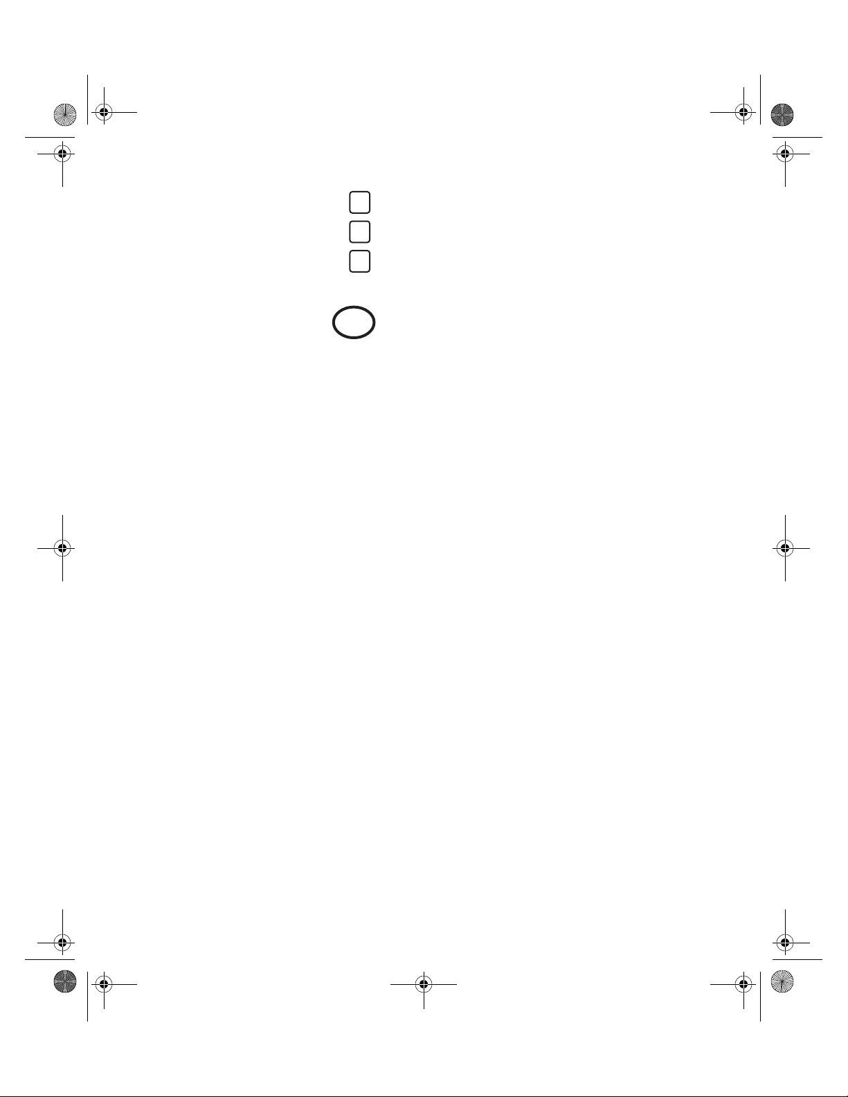
To select this option:
From main menu
Press then press (Misc’)
Press then press (Software Reset)
Press the 6 times to access the Circle-store menu
Select option 2 ‘Circle-store On’ using ; press
Press Screen will prompt: “End of setup”
Press to return to main menu
MENU
MENU MENU
6
6
Enter
16
Page 18
7529_eng.fm Page 17 Wednesday, November 12, 2003 8:57 AM
Direct Measure Mode - ETA5 ONLY
(Ingersoll-Rand TRD, TSD or
Crane UTA Type Transducers)
Direct measure mode allows an operator to connect different transducers which may have different spans and an angle output, and can switch between them using an external T switch. This is
a display only function and readings are not stored or printed out.
To start, press
ON
press
press (Direct)
press (Direct Measure)
press (Setup)
select units of measure using ; press
select peak, track, Impulse or ‘Click Dip’ using ; press
MENU
4
1
1
Enter
Enter
select measurement direction using (Right is clockwise. Left is anti-clockwise);
press
select ‘Cycle end Time’ using ; press
select frequency response using ; press
type in the Threshold Percent (mx 50.0; mn 0.0), and press
type in amount of Click (mx 100.0 Nm; mn 0.0 Nm), and press
Enter
Enter
Enter
Enter
Enter
select ‘Second Parameter’ using ; press
Screen shows “End of Setup”, press to exit
MENU MENU
press to return to main menu
MENU
17
Enter
Page 19
7529_eng.fm Page 18 Wednesday, November 12, 2003 8:57 AM
The READ option allows you to read the torque from a connected transducer.
From the main menu, press (Direct)
press (Direct Measure)
press (Read)
If no transducer is connected, display will prompt: “Insert Tx” (transducer)
connect transducer and press
Screen will show the span of the connected transducer and the torque measured in units
selected at setup. The display will show the last reading taken until the next torque input
exceeds the threshold level set.
Note: If password protection has been set on Direct measure, then exit is by
password only. A correct password returns you to the setup read submenu. Entering three incorrect passwords will force the user back
into read mode. See password protection later in this book.
4
1
2
Enter
18
Page 20
7529_eng.fm Page 19 Wednesday, November 12, 2003 8:57 AM
To set up a Characteristic - ETA5 ONLY
To set up a job
To start, press
press
ON
MENU
plug in transducer
press (Configure)
press (Edit Char)
Type in Job Name ______________________ , press
1
1
Enter
Alternatively, when the cursor is flashing, you may connect a Bar Code Reader to the Printer/PC
connector on the back of the ETA5 and scan the information from a barcode. Scan across the
label (from left or right) and watch the display. If the flashing cursor disappears, the reading has
been captured; wait a few seconds for the reading to be displayed. If not, re-scan until the data
is accepted.
When the information is displayed on the screen, press
Type in number of samples __________________ , press
Type in number of subgroups ________________ , press
Select transducer ID using , press
Enter
Enter
Enter
Enter
Select units of measure using , press
Enter
Select ‘Peak’, ‘Impulse’, or ‘Click’ using ; then press
Select measurement direction using ; then press
Select cycle end time using ; then press
19
Enter
Enter
Enter
Page 21

7529_eng.fm Page 20 Wednesday, November 12, 2003 8:57 AM
Select Frequency Response using ; then press
Enter
Note: No prompt will appear for frequency response if this value is set as a
default during a software reset.
Type in maximum torque specification __________ , then press
Type in minimum torque specification ___________ , then press
Type in threshold torque value ________________ , then press
Select ‘Second Parameter’ using , press
Enter
Enter
Enter
Enter
If you have selected ‘Click Dip’, type in amount of ‘Dip’ to be sensed, press
Note: 5% of torque value for 0 to 100 Nm and 10% of torque value for over
100 Nm generally provide excellent results.
Type in number of characters to reserve for subgroup comment, then press
To return to main menu, press
MENU MENU
Note: Repeat above steps for each additional job or characteristic. If you
wish to establish a route or ‘ROUND’, enter all of your characteristics
or jobs now.
Enter
Enter
20
Page 22

7529_eng.fm Page 21 Wednesday, November 12, 2003 8:57 AM
Direct Characteristic Mode - ETA5 ONLY
Direct characteristic mode is a quick entry method of using a pre-set characteristic and can be
used directly or stored for setting up torque measuring equipment. The characteristics used are
taken from the edit characteristic function in ETA5.
At main menu, press (Direct)
press (Direct Char)
select storage option by pressing (Do not store), or (Store)
type in the characteristic name and press . Use the and keys to scroll
through the available characteristics and press
4
2
1 2
Enter
Enter
Alternatively, when the cursor is flashing, you may connect a Bar Code Reader to the Printer/PC
connector on the back of the ETA5 and scan the information from a barcode. Scan across the
label (from left or right) and watch the display. If the flashing cursor disappears, the reading has
been captured; wait a few seconds for the reading to be displayed. If not, re-scan until the data
is accepted. If a further reading needs to be taken, press to clear the data and allow a
Reset
further scan to be taken or data to be keyed in.
When the information is displayed on the screen, press
Display now shows the status of the characteristic. Press
Enter
Enter
Display now prompts “Insert TX” (transducer)
Connect the transducer to the ETA5 and press
Enter
Torque measurement can now be taken and will be overwritten or stored depending on the
selection made previously. At the end of the subgroup of readings, the display will return to characteristic name entry line and the LEDs on the ETA5 will flash to show the subgroup status:
RED LED = One or more readings out of the specified range
GREEN LED = All readings within the specified range
21
Page 23

7529_eng.fm Page 22 Wednesday, November 12, 2003 8:57 AM
Press to accept the subgroup and prepare to accept readings for the next subgroup.
Enter
When all the subgroups are full, the display will return to characteristic name entry line
(pressing will also do this).
Enter
Note: If password protection has been set on Direct measure, then exit is by
password only. A correct password returns you the Store/Not store
sub-menu. Entering three incorrrect passwords will keep the user at
the current display. See password protection later in this book.
If Store mode has been used, results can be printed or analyzed using the appropriate ETA
Functions.
22
Page 24

7529_eng.fm Page 23 Wednesday, November 12, 2003 8:57 AM
To Store Data (single characteristic) - ETA5 ONLY
At main menu, press (Store)
press (Single Characteristic)
press
3
1
Enter
A job name will appear on screen. If more than one job has been set up in the ETA5, you can
scroll through the jobs in sequence using
You can also find your job by typing in the name after you press , then pressing
Alternatively, after pressing , when the cursor is flashing, you may connect a Bar Code
1
1
Enter
Reader to the Printer/PC connector on the back of the ETA5 and scan the information from a
barcode. Scan across the label (from left or right) and watch the display. If the flashing cursor
disappears, the reading has been captured; wait a few seconds for the reading to be displayed.
If not, re-scan until the data is accepted.
If a further reading needs to be taken, press to clear the data and allow a further scan
Reset
to be taken or data to be keyed in.
When correct job appears on screen, press
Enter
If you are using an Ingersoll-Rand TRD, TSD or Crane UTA type transducer and it is already
plugged in, you are now ready to take readings. The screen will show transducer size and Sub 1
Sam 1
If you are using any other type of transducer or it is not yet plugged in, you will be prompted to
insert transducer and select transducer type required.
Plug in correct transducer and press
Enter
When you have taken all readings, the screen will show that all torque collection is complete.
To return to the main menu, press
MENU MENU
Note: When each reading is taken you will get an audible/visual signal.
23
Page 25

7529_eng.fm Page 24 Wednesday, November 12, 2003 8:57 AM
1 beep/Amber LED = Torque value or Angle/Pulse count is low (if used)
2 beeps/Green LED = Torque value or Angle/Pulse count is OK (if used)
3 beeps/Red LED = Torque value or Angle/Pulse count is high (if used)
The final reading of a subgroup will be indicated by an extended beep.
If you make a mistake when taking a reading it can be erased by pressing .
If you continue to press you can erase all readings within the current subgroup. It is not
possible to erase readings taken in a previous subgroup.
No readings will be stored if the torque value is below the threshold value previously set.
If the characteristic has been configured with Subgroup comment size set to a value other than
0, then pressing will allow a subgroup comment to be entered.
Alternatively, when the cursor is flashing, you may connect a Bar Code Reader to the Printer/PC
connector on the back of the ETA5 and scan the information from a barcode. Scan across the
label (from left or right), and watch the display. If the flashing cursor disappears, the reading has
been captured; wait a few seconds for the reading to be displayed. If not, re-scan until the data
is accepted. If a further reading needs to be taken, press to clear the data and allow a
further scan to be taken or data to be keyed in.
When the information is displayed on the screen, press
Pressing gives analysis of last completed subgroup. (Press again to continue.)
Z
Note: If the bar code data exceeds the number of characters reserved for
# #
Reset
Reset
the comment, the ETA5 will beep and show an error message. The
data will not be accepted.
Enter
Reset
Pressing gives analysis of current subgroup, up to current reading. (Press again to
continue.)
. .
24
Page 26

7529_eng.fm Page 25 Wednesday, November 12, 2003 8:57 AM
To set up a Round - ETA5 ONLY
To set a sequence of jobs to be performed in a set order, the method detailed below should be
used.
Note: In order to set up a Round, there must be at least 2 Characteristics set
up in the ETA5.
At main menu, press (Configure)
press (Round)
press
Type in the name of your round and press
1
4
Enter
Enter
Type in the number of characteristics (jobs) that are to be included in the round and
press
Enter
Select Vertical, Horizontal or Vert+Prompt sampling using and press
Note: If you choose Vertical sampling, the ETA5 will automatically switch
between jobs at the end of each subgroup. If you select Horizontal
sampling, the switch will be made after each individual reading.
Vert+Prompt will ask you to insert a transducer at the start of each
subgroup.
Screen will show “Characteristic No 1 of ?“
Select which job you want to be the first job using and press
Enter
Screen will show “Characteristic No 2 of ?”
Select which job you want to be the second job using and press
Enter
Enter
Continue selecting jobs in this way until all jobs to be included have been selected.
Screen will now show “End of Set-up”
To return to the main menu, press
MENU MENU
25
Page 27

7529_eng.fm Page 26 Wednesday, November 12, 2003 8:57 AM
To Store Data by Round - ETA5 ONLY
At main menu, press (Store)
Press (Round)
3
2
Screen will show “Select Round No”
Select round number using and press
Enter
The maximum number of rounds that can be stored is 25.
If you are using an Ingersoll-Rand TRD, TSD or Crane UTA type transducer and it is already
plugged in, you are now ready to take readings. The job that appears on screen will be the job
that you selected to be first when you set up the round.
If you are using any other type of transducer or it is not yet plugged in, you will be prompted to
insert transducer and select transducer to be used. Plug in the transducer and press
Enter
When a complete subgroup of readings has been taken for all jobs in the round, screen will
show “Next Round Cycle “. To continue taking readings, press (this message will be
repeated at the end of each complete subgroup Sub1, Sub2, etc.)
When you have finished taking all readings, pressing will result in a message that the
round is complete. Press .
To return to the main menu, press
MENU
MENU MENU
Note: You can erase the last reading taken by pressing .
Reset
If you have selected Horizontal sampling and the ETA5 has
already switched to the next job, it will switch back when you
press .
Reset
It is not possible to erase any readings other than the last one
taken in Horizontal sampling mode.
26
Page 28

7529_eng.fm Page 27 Wednesday, November 12, 2003 8:57 AM
If the characteristic has been configured with Subgroup comment size set to a value other
than 0:
Pressing will allow a subgroup comment to be entered.
Pressing gives analysis of last completed subgroup. (Press again to continue.)
Pressing gives analysis up to current subgroup. (Press again to continue.)
Z
# #
. .
To set up a Master Round - ETA5 ONLY
To set a sequence of Rounds to be performed in a set order, the method detailed below should
be used.
Note: In order to set up Master Round, there must be at least 2 rounds set
up in ETA5.
At main menu, press (Configure)
press (Edit Master Round)
press
Type in the number of “rounds” to be included and press
1
5
Enter
Enter
Select first “round” to be included using and press
Continue selecting rounds to be included using and press
Note: When all rounds have been selected, screen will show “End of
Set-up”
To return to the main menu, press
MENU MENU
Enter
27
Enter
Page 29

7529_eng.fm Page 28 Wednesday, November 12, 2003 8:57 AM
To Store Data by Master Round
At main menu, press (Store)
Press (Master Round)
If you are using an Ingersoll-Rand TRD, TSD or Crane UTA type transducer and it is already
plugged in, you are now ready to take readings. The job that appears on screen will be the job
that you selected to be first when you set up the master round.
If you are using any other type of transducer or it is not yet plugged in, you will be prompted to
insert transducer and select transducer to be used. Plug in transducer and press
To return to the main menu, press
Note: You can erase the last reading taken by pressing . If you have
If the characteristic has been configured with Subgroup comment size set to a value other
than 0:
Pressing will allow a subgroup comment to be entered.
Z
3
3
Enter
MENU MENU
Reset
selected Horizontal sampling and the ETA5 has already switched to
the next job, it will switch back when you press .
It is not possible to erase any readings other than the last one taken
in Horizontal sampling mode.
Reset
Pressing gives analysis of last completed subgroup. (Press again to
continue.)
Pressing gives analysis up to current subgroup. (Press again to continue.)
# #
. .
28
Page 30

7529_eng.fm Page 29 Wednesday, November 12, 2003 8:57 AM
To Display Recorded Data on ETA2
From main menu, press (Display/Analyze)
Screen will show job name and Specs; press
Screen will now show x-bar, R, and sigma for total readings
From any Subgroup display, press
Screen will show the Date and Time the readings for that subgroup were taken.
Press , screen will show subgroup comment.
Press again to see the individual readings displayed in groups of four readings per screen.
9
To Display Recorded Data on ETA5
From main menu, press (Display/Analyze)
Press to display the last recorded Characteristic
Select the job that you want to see using and press
Enter
9
Enter
Screen will show job name and Specs; press
Screen will now show x-bar, R, and sigma for Sub1; press
Screen will now show same information for Sub2
You can use to go back and forth between subgroups as required
From any Subgroup display, press
Screen will show the Date and Time the readings for that subgroup were taken.
Press , screen will show subgroup comment.
29
Page 31

7529_eng.fm Page 30 Wednesday, November 12, 2003 8:57 AM
Press again to see the individual readings displayed in groups of four readings per screen.
Note: By using the four arrow keys it is possible to move back and forth
through all of the subgroups and individual readings.
To view another job, press and repeat above procedure.
MENU
To View Cp and Cpk
At the job name/spec screen press , screen will show the Cp and Cpk and the number of
samples used in the calculations.
Press , screen will now show x-bar, R and sigma based on all of the data (all subgroups
calculated together).
The number of samples that were NOK will also be displayed expressed as a percentage.
Press , screen will show the highest and lowest torque recorded and the number of
readings that were above the maximum torque value and minimum torque value.
To return to the main menu, press
For more information on Cp, Cpk and CAM, refer to the glossary.
MENU
30
Page 32

7529_eng.fm Page 31 Wednesday, November 12, 2003 8:57 AM
French Cp and Cpk
It is possible to view the French Cpk/CAM calculations as an alternative to the standard Cp
and Cpk.
Readings must be a minimum of 30 samples.
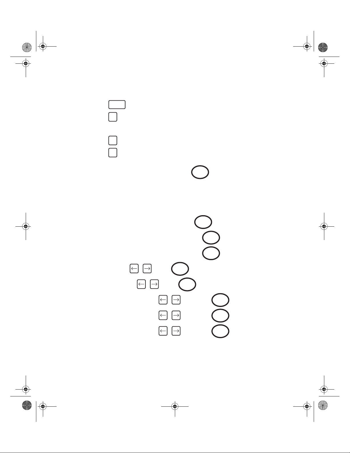
To set this function:
From main menu
Press then press (Misc’)
Press then press (Software reset)
Press 5 times to access the Cpk Calculation screen
Use the and arrow keys to access option 2 ‘French Cpk/CAM’ and press
MENU
Press to confirm, screen will prompt “End of setup”
MENU
Press to accept and exit, or to edit
MENU
Press to return to main menu
Returning to Normal Cpk calculations is done as above, selecting option 1 ‘Normal
Cpk/no CAM’
For more information on Cp, Cpk and CAM, please refer to the glossary.
6
6
To Erase Stored Data
To Erase Readings Stored in Measure Mode:
Enter
From the main menu, press
ETA will erase all readings taken in measure mode.
Y
31
Page 33

7529_eng.fm Page 32 Wednesday, November 12, 2003 8:57 AM
To Erase Stored Data and Setups on ETA5
To Erase Characteristic Setup:
At main menu, press (Configure)
press (Erase)
press (Char’ Set-up)
Select Characteristic name by pressing and select Characteristic required
1
3
1
Enter
by pressing
Press , screen will display the Characteristic number and prompt “Erase Set-up Data”
Press to erase the characteristic data or to return to Erase menu
If was pressed, display shows “Erased OK”
Press to erase more data or press to return to main menu
Enter
Enter Reset
Enter
MENU MENU MENU
To Erase Characteristic Data:
At main menu, press (Configure)
press (Erase)
press (Char’ Data)
1
3
2
Select Characteristic name by pressing and select Characteristic required by
Enter
pressing
Press , screen will display the Characteristic number and prompt “Erase data
Enter
only”
Press to erase the characteristic data or to return to Erase menu
If was pressed, display shows “Erased OK”
Press to erase more data or press to return to main menu
Enter Reset
Enter
MENU MENU MENU
32
Page 34

7529_eng.fm Page 33 Wednesday, November 12, 2003 8:57 AM
To Erase Round Data:
At main menu, press (Configure)
press (Erase)
press (Round Data)
1
3
3
Select required round by pressing , press
To erase data by round, press
To exit without erasing round data, press
To return to main menu, press
Enter
MENU
MENU MENU MENU
To Erase Round Setup Information:
At main menu, press (Configure)
Then press (Edit Round)
1
4
Select required round by pressing , press
Display shows “Round Label”, press
Reset
Enter
Enter
Round label is cleared from display. Press
Enter
Display will prompt “Erase Rnd Set-up”
To erase round setup, press ; display will then show “ROUND ERASED”
Or, press to return to Configure Menu
Reset
To return to main menu, press
Enter
MENU
33
Page 35

7529_eng.fm Page 34 Wednesday, November 12, 2003 8:57 AM
To print readings taken in measure mode:
Connect ETA to printer or computer and switch the device ON
On ETA:
Printing
Press
Press
Press then press (Print)
Press then press (Print Measure)
On
MENU
5
8
ETA will print details of stored readings taken in measure mode (with date/time stamp)
A sample printout can be found on page 45.
To return to main menu, press
MENU
To print details of Setup or Analysis of Data from ETA5
To print settings and readings taken by characteristic:
Connect ETA5 to printer or computer and switch the device ON
Ensure ETA5 is configured to printer by referring to “Configure Printer Port” section
On ETA5:
Press
Press
Press , then press (Print)
Press (Print Char’)
On
MENU
5
1
34
Page 36

7529_eng.fm Page 35 Wednesday, November 12, 2003 8:57 AM
Select Characteristic name by pressing and select Characteristic required by
Enter
pressing
To start printing, press
Enter
ETA5 will print details of setup and stored reading by characteristic name.
To print settings and data analysis of readings taken by characteristic:
Connect ETA5 to printer or computer and switch the device ON
On ETA5:
Press
Press
Press , then press (Print)
Press (Print/Analyze Char’)
On
MENU
5
2
Select Characteristic name by pressing and select Characteristic required by
Enter
pressing
To start printing, press
Enter
ETA5 will print details of setup and analysis of stored reading by characteristic name.
To print details of readings by round:
Connect ETA5 to printer or computer and switch the device ON
On ETA5:
Press
Press
On
MENU
35
Page 37

7529_eng.fm Page 36 Wednesday, November 12, 2003 8:57 AM
Press , then press (Print)
Press , then press (Print Round)
5
3
Select round by using
To start printing, press
Enter
ETA5 will print details of setup and stored reading by round name.
To print details of setup and analysis of readings by round:
Connect ETA5 to printer or computer and switch the device ON
On ETA5:
Press
Press
Press , then press (Print)
Press , then press (Print/Analyze Round)
On
MENU
5
4
Select round by using
To start printing, press
Enter
ETA5 will print details of setup and analysis of stored reading by round name.
To print details of all characteristic setups:
Connect ETA5 to printer or computer and switch the device ON
On ETA5:
Press
Press
On
MENU
36
Page 38

7529_eng.fm Page 37 Wednesday, November 12, 2003 8:57 AM
Press , then press (Print)
Press , then press (Print All Char¡¦s Setup)
5
5
ETA5 will print details of all characteristic setups which are stored.
To print details of a particular round setup:
Connect ETA5 to printer or computer and switch the device ON
On ETA5:
Press
Press
Press , then press (Print)
Press , then press (Print Round Setup)
On
MENU
5
6
Select round by using
To start printing, press
Enter
ETA5 will print details of all round setups which are stored.
To print readings taken by characteristic:
Connect ETA5 to printer or computer and switch the device ON
On ETA5:
Press
Press
Press , then press (Print)
Press , then press (Print Char’ Readings)
Select Characteristic name by pressing and select Characteristic required by
On
MENU
5
7
Enter
pressing
37
Page 39

7529_eng.fm Page 38 Wednesday, November 12, 2003 8:57 AM
To start printing, press
Enter
ETA5 will print details of readings taken by characteristic.
To print readings taken in measure mode:
Connect ETA5 to printer or computer and switch the device ON
On ETA5:
Press
Press
Press , then press (Print)
Press , then press (Print Measure)
On
MENU
5
8
ETA5 will print details of stored readings taken in measure mode (with date/time stamp)
A sample printout can be found on page 45.
To return to main menu, press
MENU
To print setup and readings for all used characteristics containing readings:
Connect ETA5 to printer or computer and switch the device ON
On ETA5:
Press
Press
Press , then press (Print)
Press , then press (Print All Used Chars’)
On
MENU
5
9
ETA5 will print details of stored characteristic setups containing readings.
A sample printout can be found on page 46.
To return to main menu, press
MENU
38
Page 40

7529_eng.fm Page 39 Wednesday, November 12, 2003 8:57 AM
Printing Data to PC
Most data that can be sent to a printer may also be sent to a PC. Follow the same instructions
for printing. Connect the cable to the PC using Com 1. Use Hyper Terminal (found under Accessories) or other communication programs.
Note: Be sure communication protocols are set the same on the PC
and ETA.
To Set Date and Time
From main menu:
Press then press (Misc)
Press (Set Date/Time)
Select date format using
Enter date and time and press
To return to main menu, press
1
6
Enter
MENU MENU
39
Page 41

7529_eng.fm Page 40 Wednesday, November 12, 2003 8:57 AM
To Set Power Off and Backlight Time Delays
From main menu:
Press then press (Misc)
Press (Select Power Off/Backlight Time Delays)
2
6
Select Power Off time delay using Press
Select Backlight Delay using Press
To return to main menu press
MENU MENU
Enter
To Configure Printer Port
From main menu:
Press then press (Misc)
Press then press (Printer port)
Select Baud Rate using then press
Select number of data bits using then press
6
3
Enter
Enter
Enter
Select number of Stop Bits using then press
Select Parity using then press
To return to main menu press
MENU MENU
Enter
40
Enter
Page 42

7529_eng.fm Page 41 Wednesday, November 12, 2003 8:57 AM
To Display Software Version Number
From main menu:
Press then press (Misc)
Press then press (Version #)
To return to main menu, press
6
4
MENU MENU
To Set Password Protection
From main menu:
Press then press (Misc)
Press then press (Password)
Screen will prompt “Enter new Password”
Type in the password (4 characters) and press
Screen will prompt “confirm password”
Press to accept or to reject
Select desired option using
Options for protection are:
Enter Reset
1- Power up
2- Configure
3- Direct Measure
4- Direct Characteristic
5- Software Reset
6- Date and Time
6
5
Enter
Press to protect your selected option or to exit
#
Note: When an option is password protected, ‘ ’ appears in the top right
of the display window.
Pressing will remove the protection.
#
MENU
41
#
Page 43

7529_eng.fm Page 42 Wednesday, November 12, 2003 8:57 AM
MENU
Press to exit
Display now reads “End of setup”
To return to main menu press or press to edit password protection
MENU
The remaining options can be password protected in the same manner.
To Clear Password Protection
From main menu:
Press then press (Misc)
Press then press (Password)
Screen will prompt “Password” - - - - enter the existing password (4 characters) and
press
Enter
Screen will prompt “Confirm Password” and display the existing password
Press to confirm or press to clear the password protection
Enter Reset
Screen will prompt “Enter new Password”
Press to clear the password (keying in 4 characters before pressing
Enter Enter
will result in a new password being created)
6
5
Screen will say “Confirm password”
Press to confirm and password is cleared
Enter
Notes on Password Protection:
Be aware of the implications of password protection. Always keep a note of the chosen
password somewhere safe. As there is no function to enable an existing password to be
removed without it first being entered, it may be advisable for the person who is ultimately
responsible for the ETA to initially set a password and issue it only to personnel who need the
information. This will prevent an unknown password being entered, accidentally or deliberately,
without anyone else’s knowledge. If an unknown password is encountered, please contact
Ingersoll-Rand for advice.
42
Page 44

7529_eng.fm Page 43 Wednesday, November 12, 2003 8:57 AM
To Perform Software Reset
CAUTION: Use of this function will result in the loss of all stored data. Following this
procedure will return the ETA to its factory default state. This feature should
only be used when it is desired to clear all settings from the ETA.
From main menu:
Press then press (Misc)
Press then press (S/W Reset)
6
6
Press the key 8 times to access the Software Reset screen
Screen will display “Erase all data and set mode?”
To carry out S/W reset, press
To exit without performing S/W reset, press
Enter
MENU
Screen will display “ERASING ALL CHARACTERISTICS ROUNDS AND MASTER ROUNDS”
- wait a moment for display to change
Select Subgroup mode using and press screen will display “End of setup”
To return to main menu, press
MENU MENU
Enter
There are a number of other parameters which are set from the Software Reset Menu, some of
which are detailed elsewhere in this manual.
Pressing after making a selection will take the user on to the next screen.
Pressing will give the user the option to exit to the Misc menu by pressing or
Enter
MENU MENU
continuing to edit by pressing .
Screens can be skipped using the and keys.
43
Page 45

7529_eng.fm Page 44 Wednesday, November 12, 2003 8:57 AM
Settings in the order they appear when the Software Reset Menu is accessed.
Cm max samples - type in the required figure
Cm min samples - type in the required figure
Language - select using
Autoprint mode - select using
Capability label - select using
Cpk Calculation - select using
Circle-store (On/Off) - select using
Shift key mode - select using
To Communicate with a PC
using PC Comms Software
Connect ETA5 to PC via cable provided
On PC, start PC Comms
On ETA5:
Press
Press
Press , then press
You can now setup and view all information/data via the PC
Note: This optional PC software is used primarily to write and store
On
MENU
8
characteristics and rounds on the PC. The format of the data
stored on the PC is of little use to the computer operator without
further processing.
44
Page 46

7529_eng.fm Page 45 Wednesday, November 12, 2003 8:57 AM
Example Printout of Readings taken in Measure Mode
MEASURE-Peak Capability Results Torque
----------------------------------- ---------------------------
No of Samples 200 Based on last 15. samples
Transducer C I/S 75.00 Nm /x 6.96 Nm
Serial Number: 99999 Range 8.30 Nm
Measurement Dir Right Sigma 2.210
Max Torque Value 20.00 Nm Cp 0.754
Min Torque Value 10.00 Nm Cpk - 0.458
Thrshld Torq Val 2.00 Nm Max found 12.65 Nm
Freq response 1676 Hz Min found 4.35 Nm
Cycle end time 0.1 Sec Readings above max 0.
Date Time Torque
1 07/01/95 12:38:32 7.21 LO
2 07/01/95 12:38:35 4.87 LO
3 07/01/95 12:38:38 6.65 LO
4 07/01/95 12:38:40 6.56 LO
5 07/01/95 12:38:42 7.45 LO
6 07/01/95 12:38:45 5.76 LO
7 07/01/95 12:38:47 7.07 LO
8 07/01/95 12:38:49 12.65
9 07/01/95 12:38:52 9.37 LO
10 07/01/95 12:38:54 5.29 LO
11 07/01/95 12:38:56 6.09 LO
12 07/01/95 12:38:59 4.35 LO
13 07/01/95 12:39:01 5.90 LO
14 07/01/95 12:39:04 5.25 LO
15 07/01/95 12:39:06 10.03
Readings below min 13.
Percentage not OK 86.66 %
45
Page 47

7529_eng.fm Page 46 Wednesday, November 12, 2003 8:57 AM
Printout of Setup and Readings taken by Characteristic
Ingersoll-Rand ETA5 08/01/01 11:59:44
Characteristic WHEELNUT Capability Results Torque
----------------------------------- ---------------------------
No of Samples 4 Based on last 8. samples
No of Sub-groups 2
Transducer A TRD 75.00 Nm /x 13.93 Nm
Serial Number: 99999 Range 17.21 Nm
Measurement Dir Right Sigma 5.936
Max Torque Value 14.00 Nm Cp 0.224
Min Torque Value 6.00 Nm Cpk 0.003
Thrshld Torq Val 2.00 Nm Max found 22.17 Nm
Freq response 1676 Hz Min found 4.96 Nm
Cycle end time 0.1 Sec Readings above max 4.
Readings below min 1.
Percentage not OK 62.50 %
Sg-sp Date Time Torque
1 1 08/01/01 11:31:16 4.96 LO
12 12.28
13 9.79
14 8.81
/x 8.96
Range 7.32
Sigma 3.040
2 1 08/01/01 11:31:46 15.70 HI
22 18.93 HI
23 21.17 HI
24 18.84 HI
/x 18.91
Range 6.47
Sigma 2.641
46
Page 48

7529_eng.fm Page 47 Wednesday, November 12, 2003 8:57 AM
Printout of Analysis by Characteristic
Ingersoll-Rand ETA5 08/01/01 11:45:36
Characteristic WHEELNUT Capability Results Torque
----------------------------------- ---------------------------
No of Samples 4 Based on last 8. samples
No of Sub-groups 2
Transducer A TRD 75.00 Nm /x 13.93 Nm
Serial Number: 99999 Range 17.21 Nm
Measurement Dir Right Sigma 5.936
Max Torque Value 14.00 Nm Cp 0.224
Min Torque Value 6.00 Nm Cpk 0.003
Thrshld Torq Val 2.00 Nm Max found 22.17 Nm
Freq response 1676 Hz Min found 4.96 Nm
Cycle end time 0.1 Sec Readings above max 4.
Readings below min 1.
Percentage not OK 62.50 %
Sg-sp Date Time Torque
1 08/01/01 11:31:16 /x 8.96
Range 7.32
Sigma 3.040
2 08/01/01 11:31:46 /x 18.91
Range 6.47
Sigma 2.641
47
Page 49

7529_eng.fm Page 48 Wednesday, November 12, 2003 8:57 AM
Printout of details of all Characteristic setups
Ingersoll-Rand ETA5 08/02/01 14:36:22
----------------------------------- ---------------------------
Name smpl sgrp transducer direc max min thr units
WHEELNUTS 16 3 A TRD 11.29 Nm Right 8. 6. 2. Nm
EX MANIFOLD 6 3 A TRD 11.29 Nm Right 10. 6. 3. Nm
DOORLOCK 3 3 A TRD 11.29 Nm Right 9. 7. 3. Nm
48
Page 50

7529_eng.fm Page 49 Wednesday, November 12, 2003 8:57 AM
Printout of Round setup
Ingersoll-Rand ETA5 08/02/01 14:51:26
----------------------------------- ---------------------------
Round 1
Round Label CAVALIER Complete Setup
Sampling Vertical
No of charact s 3
Characteristic 1 DOORLOCK Complete Setup
Characteristic 2 WHEELNUTS All Data Stored
Characteristic 3 EX MANIFOLD Complete Setup
49
Page 51

7529_eng.fm Page 50 Wednesday, November 12, 2003 8:57 AM
Printout of Readings taken by Characteristic
5.90
6.28
7.39
2.90
2.87
3.46
3.62
3.19
3.23
3.07
3.78
4.03
4.01
2.93
3.07
2.70
4.51
3.63
4.99
4.06
4.25
7.53
6.10
2.90
4.71
5.64
5.62
7.78
5.19
5.72
9.74
5.16
8.22
6.27
5.42
5.38
6.22
5.84
7.70
7.01
4.98
5.71
5.52
7.40
5.98
5.11
8.33
5.93
10.0
9.0
10.0
5.0
4.0
5.0
5.0
6.0
3.0
5.0
4.0
5.0
6.0
4.0
3.0
3.0
4.0
4.0
4.0
2.0
4.0
4.0
4.0
3.0
3.0
4.0
3.0
3.0
2.0
4.0
5.0
5.0
1.0
4.0
3.0
3.0
3.0
3.0
3.0
3.0
3.0
3.0
3.0
3.0
3.0
3.0
3.0
4.0
50
Page 52

7529_eng.fm Page 51 Wednesday, November 12, 2003 8:57 AM
Rotary and Stationary Joint Kits
Introduction
The joint kits are designed as a convenient, repeatable, variable stiffness joint for assessing the
performance of torque tools. They can be used with the Ingersoll-Rand stationary (static) or
rotary transducers.
Each kit may be assembled in different ways to vary the stiffness of the joint. Reference Table 1,
to select from the available options. Care should be taken to ensure that the maximum torque
for the joint is not exceeded. Please note that the joint kit is not designed to provide an exact
joint stiffness and that the rates shown in Table 1 are given as rough guide only.
Joint Assessment
The first task is to choose the stiffness of the joint that the tool will be used to assemble. This is
best done with a torque wrench on an actual production part. If available an angle measurement
protractor may be used, but this is not essential. Tighten the fastener until it is snug, note the
torque Ts in Nm (or lbft). Tighten to the required target torque Tf Nm (or lbft), and note the angle
of rotation E in degrees. The required joint stiffness may now be calculated. The resulting units
are degrees per Nm (or degrees per lbft).
E / (Tf-Ts) Ts = Snug Torque
Tf = Target Torque
E = Angle
It should be noted that for packaging convenience Joint Kits will be delivered assembled with full
stacks of belleville washers. The spacers will be bagged separately. The Joint Kits DO NOT
represent a usable joint without adjustment to the required stiffness. A Pictorial guide to the
description of components is shown in Figure 2. Table 2 shows the parts available for each
model.
Joint Assembly
Having selected the required joint stiffness from Table 1, count out the number of Belleville
washers required for the first and second stacks. Grease each washer and assemble the first
stack around the bolt, such that the internal diameter rests against the shoulder of the bolt.
Invert the second stack such that the outside diameters of the last and first washers in the two
stacks touch. If only one stack is to be fitted, it should be mounted such that the external
diameter rests against the bolt shoulder. Select and fit the spacer required to complete the joint.
After greasing the bearing surface, slide the assembly into the external sleeve, fit the end collar
and secure by applying the retaining clip.
51
Page 53

7529_eng.fm Page 52 Wednesday, November 12, 2003 8:57 AM
The base plate or transducer, depending on model, should be mounted onto a rigid surface.
See Figure 1 for bolt hole pattern. Place the bolt assembly just completed into the shroud and
then onto the transducer or base plate. The last step is to apply the steel washer onto the bolt
before applying the nut.
IMPORTANT - Grease the threads and fit the nut.
The joint is now ready for use. Eventually the bolt and nut threads will wear and will need to be
replaced. IR recommends replacing worn joints with the appropriate bolt kit that matches your
joint kit model: JKS30-BKIT, JKS150-BKIT, JKS300-BKIT or JKS1000-BKIT.
- Ensure that the threads are kept clean and lubricated.
Nominal Joint Stiffnesses
Joint
Kit
Deg/Nm Deg/lbin Nm lbin
1/4” 50 6 5.65 50 3 3 17.1
3/8” 6 8 67.8 50 5 5 15.5
1/2” 3 4 135.6 100 5 5 19.5
3/4” 0.88 1.2 460 340 5 3 39.5
Rate Max Torque 1st
Stack
30 3.4 13.5 120 6 6 11.5
20 2.2 21.5 190 12 12 -
8 0.9 28.25 250 24 - -
3.5 0.4 28.25 250 - - 11.5+12.3
Deg/lbft lbft
4 5.5 120 90 9 9 -
2 2.5 100 73.75 16 - 5
1 1.3 100 73.75 - - 5+18.6+15.5
2 2.7 220 160 9 9 -
1.1 1.5 271 200 9 - 23.3
0.4 0.55 271 200 - - 3.9+23.3+19.5
0.55 0.7 830 610 10 5 -
0.35 0.5 775 570 10 - 41.3
0.11 0.15 1017 750 - - 39.2+41.3
2nd
Stack
Spacer(s)
mm
Ta ble 1
Failure to mount the base plate or transducer, depending on model,
could result in injury.
52
Page 54

7529_eng.fm Page 53 Wednesday, November 12, 2003 8:57 AM
Bolt Hole Pattern, in mm.
Figure 1.
(Dwg. TPA1919)
Figure 2.
Sectional View.
53
(Dwg. TPA1923)
Page 55

7529_eng.fm Page 54 Wednesday, November 12, 2003 8:57 AM
Parts List
Callout
Number
1 M8X55 Square Bolt JKS30-800 JKS150-120
2 M8 Nut JKS30-80 JKS150-102
3 Washers JKS30-81 JKS150-121
4 Thrust Plate JKS30-11 JKS150-11
5 Spacer (Set of 3) JKS30-10-3 JKS150-10-3
6 Belleville Washer
7 Shroud JKS30-727,
8* Base Plate JKR20-13 JKR75-13
Not
Pictured
Callout
Number
1 M8X55 Square Bolt JKS300-160 JKS1000-240
2 M8 Nut JKS300-106 JKS1000-204
3 Washers JKS300-161 JKS1000-241
4 Thrust Plate JKS300-11 JKS1000-11
5 Spacer (Set of 3) JKS300-10-3 JKS1000-10-3
6 Belleville Washer
7 Shroud JKS300-727,
8* Base Plate JKR180-13 JKR500-13
Not
Pictured
Nuts, Belleville Washers Set
Nuts, Belleville Washers Set
Description Joint Kit
(Set of 18 or 20)
Bolt Kit - Includes 1 Bolt, 2
Description Joint Kit
(Set of 18 or 20)
Bolt Kit - Includes 1 Bolt, 2
Joint Kit
JKR20 & JKS30
Part #
JKS30-904-18 JKS150-906-18
JKR20-727*
JKS30-BKIT JKS150-BKIT
JKR180 & JKS300
Part #
JKS300-908-18 JKS1000-912-20
JKR180-727*
JKS300-BKIT JKS1000-BKIT
JKR75 & JKS150
Part #
JKS150-727,
JKR75-727*
Joint Kit
JKR500 & JKS1000
Part #
JKS1000-727,
JKR500-727*
Ta ble 2
Note: Items denoted with (*) are only used with JKR20, JKR75, JKR180 and JKR500.
54
Page 56

7529_eng.fm Page 55 Wednesday, November 12, 2003 8:57 AM
Glossary of Terms
Characteristic Specification of one particular torque value to be collected. Each
Cp This is a capability index which shows the process capability potential but
CpK This is an index which indicates whether the process will produce units within
characteristic has a name of up to 14 characters. ETA5 can store up to 48
different characteristics at any one time.
takes no account of how centred the process is. This is used for capability
studies and Cp may range in value from 0 to infinity. A large value indicates
greater potential capability and a value of 1.33 or greater is desirable.
or
Max -- Min
6
(x-- M i n )
3
Cp =
(Max and Min are limit values)
the tolerance limits. If the process is centred on the nominal value then CpK
will have a value equal to Cp. For values of CpK between 0 and 1 then some
of the 6 sigma spread will fall outside tolerance limits but for values greater
then 1 these will all be within tolerance. A negative value of CpK indicates
that the process mean is outside tolerance limits. A value of 1.33 or greater is
desirable.
CpK = lesser of
(Max -- x )
3
(Max and Min are limit values)
CAM This is an alternative capability index requiring a minimum of 30 readings to
be taken. In this implementation, 5 sub-groups of 6 samples are used for
each calculation. The CAM calculation uses the following formula:
Max -- Min x Cam Factor *
6 x Average Sample Value
* CAM Factor is taken from a table
(in the case of 5 x 6 samples = 1.910)
55
Page 57

7529_eng.fm Page 56 Wednesday, November 12, 2003 8:57 AM
High Output Transducer (H/O)
Torque transducer with no coding links but internal pre-amplifier giving an
output signal level of typically 1 or 2 volts.
Horizontal Sampling
Collection of data by round, taking one reading for each characteristic in turn.
Industry Standard Transducer (I/S)
Type of transducer, with no pre-amplifier or coding links, but with the exact
rated torque, marked on the body.
Master Round A sequence of up to five rounds. It is used to allow a collection sequence,
which is part vertical, part horizontal.
Max Torque Value
Upper tolerance level of any reading. This can equal but not exceed the
torque rating of the transducer to be used.
Min Torque Value
Lower tolerance level of any reading.
No. of Sub Groups
Number used to allocate memory space in ETA, for a particular characteristic. May be set in the range of 1 to 99.
Round A sequence of characteristics to be collected either horizontally or vertically.
Each round has a name of up to 14 characters.
Sample Individual torque reading.
Standard Deviation σ
Is a measure of the variation of the samples of a statistical group. If a group
of ‘n’ values has a mean of ‘x’ then its standard deviation is given by:
56
Page 58

7529_eng.fm Page 57 Wednesday, November 12, 2003 8:57 AM
Sub-Group Grouping of samples to enable analysis, with an allowable range of 1-50.
Threshold Torque Value
Level of torque in which a signal must rise above and then fall below to be
considered a valid torque cycle. This may be set in the range of 1 to 50% of
rated span or the Min Torque Value, whichever is the lower.
Units of Measure
It is possible with ETA to read a transducer calibrated in for instance, Nm,
and convert internally to display and store in any of the other torque units.
Vertical Prompt Collection of data by round, where a full sub-group is collected for a char-
acteristic, before stepping to the next characteristic.
Vertical Plus Prompt
Identical in procedure to that of Vertical mode except that before stepping to
the next characteristic, ETA5 will prompt for the fitting of a transducer (even
though the correct one is installed) and will require the ENTR key to be
pressed. Stepping to the next characteristic, ETA5 will prompt for the fitting of
a transducer (even though the correct one is installed) and will require the
ENTR key to be pressed.
57
Page 59

7529_eng.fm Page 58 Wednesday, November 12, 2003 8:57 AM
Error Messages
Code Message Explanation
101 RANGE The selection made is not within the allowable
104 EXISTS The characteristic name entered already exists.
105 NO SPACE Insufficient memory space is available to create a
106 NONE No characteristics have been created.
107 ON PC Characteristic or round was sent from PC. These
range. See the limits specified max to min.
new characteristic.
may not be edited or erased on ETA.
108 CONV’ OUT
OF RANGE
109 NO NAME A characteristic name must be entered.
110 NO SETUP The characteristic exists but configuration is not
111 NO DATA The characteristic exists, but no data is stored.
113 DAT STR More than one sub group of data is now stored.
114 ALL STR All of the sub groups for this characteristic have
120 NO Tx Transducer has been selected but none is
121 TxID - FLT Transducer ID level not recognized. Use another
122 AZ OFSET An auto-zero calibration on the transducer has
The units selected would generate too great or
too small a number.
complete.
now been collected. Erase these after printing to
allow further collection.
connected.
transducer or get transducer recalibrated.
detected an excessive offset from zero.
58
Page 60

7529_eng.fm Page 59 Wednesday, November 12, 2003 8:57 AM
Code Message Explanation
123 AZ DISCR An auto-zero calibration on the transducer has
124 Tx FAULT Adc saturation due to transducer fault, no
200 INCOR-TX The correct transducer is not connected.
300 IN ROUND This characteristic has already been included in
301 CHARACTS A minimum of two characteristics must be defined
306 RS232 Invalid RS232 data on the serial input.
400 INVALID Incorrect time or date format.
600 ONLY 1 Only one round programmed so not possible to
detected an excessive discrepancy between the
Tracking and Peak inputs.
transducer fitted or over torque.
the round.
before entering Edit Round.
generate master round.
601 NO RND No rounds programmed so not possible to gener-
ate master round.
602 IN M RND This round has already been entered into the
master round. It is not possible to enter a round
twice.
701 RND COMP The round is complete, no skipping is allowed.
702 ALL SKIP All other characteristics have already been
skipped.
800 MEMORY Message on power up if memory error found.
(See note below)
801 MENU ERR Invalid menu entered due to fault.
802 PROM CKS The EPROM has an error.
59
Page 61

7529_eng.fm Page 60 Wednesday, November 12, 2003 8:57 AM
Code Message Explanation
803 OP CODE ERR The processor has attempted to execute an
804 STACK ERR The processor stack has overflowed.
901 TX SPEC Illegal transducer specification number received
902 TX TYPE Illegal transducer type received from PC.
904 TX UNITS Illegal transducer units data received from PC.
905 SERIAL Illegal serial transducer data received from PC.
906 UNITS Illegal units of measure data received from PC.
907 DIRECT Illegal direction data received from PC.
908 NAME Name sent from PC is too long.
909 RANGE Numeric Parameter sent from PC is out of range.
illegal instruction.
from PC.
920 RS232 Error receiving RS232 data from PC.
921 TIMEOUT Timed out receiving message from PC.
922 CRC Message received from PC has incorrect CRC
value.
923 ILL MSG Illegal message received from PC.
NOTE: If ETA can be switched on, but fails to respond to the keyboard, the electronic
circuitry may be reset by linking pins 5 and 6 in the PC connector, with a length of wire. This
will turn the unit off. Turn the unit on again by pressing ‘ON’. If after this reset ETA still fails
to operate correctly, use ‘6’ for Miscellaneous and ‘6’ Software Reset to clear memory.
Having carried out a hardware reset as described above the message ‘800 MEMORY’
may be displayed on the next power up, and a software reset should be carried out.
60
Page 62

7529_eng.fm Page 61 Wednesday, November 12, 2003 8:57 AM
External Connections
61
(Dwg. TPA1822)
Page 63

7529_eng.fm Page 62 Wednesday, November 12, 2003 8:57 AM
62
Page 64

7529_eng.fm Page 63 Wednesday, November 12, 2003 8:57 AM
63
Page 65

7529_eng.fm Page 64 Wednesday, November 12, 2003 8:57 AM
64
Page 66

0102 Printed in USA
P7529_Cover_eng.qxd 8/7/03 8:54 AM Page 2
 Loading...