

Ingersoll-Rand EAC180A, EAC210A, EAC240A, EAC300A Installation, Operation And Maintenance Manual
Installation, Operation,
and Maintenance
Packaged Rooftop Air Conditioners
Foundation™ Electric/Electric
15 – 25 Tons, 60Hz
Model Numbers:
Only qualified personnel should install and service the equipment. The installation, starting up, and servicing of heating, ventilating, and airconditioning equipment can be hazardous and requires specific knowledge and training. Improperly installed, adjusted or altered equipment
by an unqualified person could result in death or serious injury. When working on the equipment, observe all precautions in the literature and
on the tags, stickers, and labels that are attached to the equipment.
November 2015
EAC180-300
SAFETY WARNING
RT-SVX50C-EN
Introduction
Read this manual thoroughly before operating or servici ng
this unit.
Warnings, Cautions, and Notices
Safety advisories appear throughout this manual as
required. Your personal safety and the proper operation of
this machine depend upon the strict observance of these
precautions.
The three types of advisories are defined as follows:
WARNI NG
Proper Field Wiring and Grounding
Required!
Failure to follow code could result in death or serious
injury. All field wiring MUST be performed by qualified
personnel. Improperly installed and grounded field
wiring poses FIRE and ELECTROCUTION hazards. To
avoid these hazards, you MUST follow requirements for
field wiring installation and grounding as described in
NEC and your local/state electrical codes.
WARNING
CAUTIONs
NOTICE
Indicates a potentially hazardous
situation which, if not avoided, could
result in death or serious injury.
Indicates a potentially hazardous
situation which, if not avoided, could
result in minor or moderate injury. It
could also be used to alert against
unsafe practices.
Indicates a situation that could result in
equipment or property-damage only
accidents.
Important Environmental
Concerns
Scientific research has shown that certain man-made
chemicals can affect the earth’s naturally occurring
stratospheric ozone layer when released to the
atmosphere. In particular, several of the identified
chemicals that may affect the ozone layer are refrigerants
that contain Chlorine, Fluorine and Carbon (CFCs) and
those containing Hydrogen, Chlorine, Fluorine and
Carbon (HCFCs). Not all refrigerants containing these
compounds have the same potential impact to the
environment. Trane advocates the responsible handling of
all refrigerants-including industry replacements for CFCs
such as HCFCs and HFCs.
Important Responsible
Refrigerant Practices
Trane believes that responsible refrigerant practices are
important to the environment, our customers, and the air
conditioning industry. All technicians who handle
refrigerants must be certified. The Federal Clean Air Act
(Section 608) sets forth the requirements for handling,
reclaiming, recovering and recycling of certain
refrigerants and the equipment that is used in these
service procedures. In addition, some states or
municipalities may have additional requirements that
must also be adhered to for responsible management of
refrigerants. Know the applicable laws and follow them.
WARNI NG
Personal Protective Equipment (PPE)
Required!
Installing/servicing this unit could result in exposure to
electrical, mechanical and chemical hazards.
• Before installing/servicing this unit, technicians
MUST put on all PPE required for the work being
undertaken (Examples; cut resistant gloves/sleeves,
butyl gloves, safety glasses, hard hat/bump cap, fall
protection, electrical PPE and arc flash clothing).
ALWAYS refer to appropriate Material Safety Data
Sheets (MSDS)/Safety Data Sheets (SDS) and OSHA
guidelines for proper PPE.
• When working with or around hazardous chemicals,
ALWAYS refer to the appropriate MSDS/SDS and
OSHA/GHS (Global Harmonized System of
Classification and Labelling of Chemicals) guidelines
for information on allowable personal exposure
levels, proper respiratory protection and handling
instructions.
• If there is a risk of energized electrical contact, arc, or
flash, technicians MUST put on all PPE in accordance
with OSHA, NFPA 70E, or other country-specific
requirements for arc flash protection, PRIOR to
servicing the unit. NEVER PERFORM ANY
SWITCHING, DISCONNECTING, OR VOLTAGE
TESTING WITHOUT PROPER ELECTRICAL PPE AND
ARC FLASH CLOTHING. ENSURE ELECTRICAL
METERS AND EQUIPMENT ARE PROPERLY RATED
FOR INTENDED VOLTAGE.
Failure to follow instructions could result in death or
serious injury.
© 2015 Trane All rights reserved RT-SVX50C-EN
WARNING
Proper Field Wiring and Grounding
Required!
All field wiring MUST be performed by qualified
personnel. Improperly installed and grounded field
wiring poses FIRE and ELECTROCUTION hazards. To
avoid these hazards, you MUST follow requirements for
field wiring installation and grounding as described in
NEC and your local/state electrical codes. Failure to
follow code could result in death or serious injury.
NOTICE:
Water Damage!
Non-factory penetrations through the base of this unit
are not allowed. Any penetration in the base of the unit
may affect the water tight integrity of the unit and lead
to water leaks into the conditioned space. Failure to
follow instructions could result in equipment and
property damage.
Overview of Manual
Note: One copy of this document ships inside the control
panel of each unit and is customer property. It must
be retained by the unit’s maintenance personnel.
This booklet describes proper installation, operation, and
maintenance procedures for air cooled systems.
By carefully reviewing the information within this manual
and following the instructions, the risk of improper
operation and/or component damage will be minimized.
It is important that periodic maintenance be performed to
help assure trouble free operation. A maintenance
schedule is provided at the end of this manual.
Should equipment failure occur, contact a qualified
service organization with qualified, experienced HVAC
technicians to properly diagnose and repair this
equipment.
Introduction
Revision Summary
RT-SVX50B-EN (23 Nov 2015)
• Added 380V/60Hz Units.
• Updated Model Number Description Section
Copyright
This document and the information in it are the property of
Trane, and may not be used or reproduced in whole or in
part without written permission. Trane reserves the right
to revise this publication at any time, and to make changes
to its content without obligation to notify any person of
such revision or change.
Trademarks
All trademarks referenced in this document are the
trademarks of their respective owners.
RT-SVX50C-EN 3

Table of Contents
Model Number Description . . . . . . . . . . . . . . . 5
General Information . . . . . . . . . . . . . . . . . . . . . 6
Unit Inspection . . . . . . . . . . . . . . . . . . . . . . . . 6
Precautionary Measures . . . . . . . . . . . . . . . . 6
Storage . . . . . . . . . . . . . . . . . . . . . . . . . . . . . . 6
Unit Description . . . . . . . . . . . . . . . . . . . . . . . 6
System Input Devices & Functions . . . . . . . 7
Sensors . . . . . . . . . . . . . . . . . . . . . . . . . . . . . . 7
Initiation of Operating Modes - JADE Controller
. . . . . . . . . . . . . . . . . . . . . . . . . . . . . . . . . . . 8
Dimensional Data . . . . . . . . . . . . . . . . . . . . . . . . 9
Unit Weights . . . . . . . . . . . . . . . . . . . . . . . . . . . 15
Rigging . . . . . . . . . . . . . . . . . . . . . . . . . . . . . . 15
Installation . . . . . . . . . . . . . . . . . . . . . . . . . . . . . 16
Unit Foundation . . . . . . . . . . . . . . . . . . . . . . 16
General Unit Requirements . . . . . . . . . . . . 16
Main Unit Power . . . . . . . . . . . . . . . . . . . . . 18
Factory-Mounted Unit Options . . . . . . . . . . . 21
Unit Disconnect (FIYUDC) . . . . . . . . . . . . . . 21
Unit Economizer Control (ECA) . . . . . . . . . .29
Wiring Diagrams . . . . . . . . . . . . . . . . . . . . . . . .30
Warranty . . . . . . . . . . . . . . . . . . . . . . . . . . . . . . .31
Central Air Conditioner . . . . . . . . . . . . . . . . .31
Pre Start . . . . . . . . . . . . . . . . . . . . . . . . . . . . . . . 22
Verifying Proper Air Flow (Units with Belt
Drive Indoor Fan)
Electromechanical Controls
Test Procedure
. . . . . . . . . . . . . . . . . . . . . 22
. . . . . . . . . . . . . . . . . . . . . . . 22
Start Up . . . . . . . . . . . . . . . . . . . . . . . . . . . . . . . 23
Standard Economizer Start-Up . . . . . . . . . 23
LLE Controls Test Procedure . . . . . . . . . . . 23
Compressor Start-Up . . . . . . . . . . . . . . . . . 23
Heating Start-Up . . . . . . . . . . . . . . . . . . . . . 24
Final System Set Up . . . . . . . . . . . . . . . . . . 24
Maintenance . . . . . . . . . . . . . . . . . . . . . . . . . . . 25
Fan Belt Adjustment—Belt Drive Units . . 25
Monthly Maintenance . . . . . . . . . . . . . . . . . 26
Final Process . . . . . . . . . . . . . . . . . . . . . . . . . 27
Troubleshooting . . . . . . . . . . . . . . . . . . . . . . . . 28
Standard Troubleshooting . . . . . . . . . . . . . 28
Low Leak Economizer
(LLE) Troubleshooting
Resetting Cooling and Heating Lockouts . 29
. . . . . . . . . . . . . . . . . 28
4 RT-SVX50C-EN

Model Number Description
Model Number Description
EAC 180 A 3 E G A 00
123 456 7 8 9 10 11 1213
Digit 1 — Unit Type
E = Packaged Cooling, Electric Heat
Digit 2 — Efficiency
A = ASHRAE 90.1 - 2010
Digit 3 — Airflow Configuration
C = Convertible
D = Downflow Only
4
Digit 4, 5, 6 — Nominal Gross
Cooling Capacity (MBh)
180 = 15 Tons
210 = 17½ Tons
240 = 20 Tons
300 = 25 Tons
Digit 7 — Major Design
Sequence
A
Digit 8 — Voltage Selection
3 = 208-230/60/3
4 = 460/60/3
W = 575/60/3
K = 380/60/3
6
Digit 9 — Unit Controls
E = Electromechanical
Digit 10 — Heating Capacity
0 = No Heat
G = 18 kW Electric Heat
N = 36 kW Electric Heat
P = 54 kW Electric Heat
R = 72 kW Electric Heat
Digit 11 — Minor Design
Sequence
J = Low Leak Economizer, Dry Bulb
w/o Barometric Relief
L = Low Leak Economizer, Reference
Enthalpy w/o Barometric Relief
N = Low Leak Economizer,
Comparative Enthalpy w/o
Barometric Relief
4
4
Digit 15 — Supply Fan/Drive
Type/Motor
0=Standard Motor
1 = Oversized Motor
7 = Multi-Speed Standard Motor
9 = Multi-Speed Oversized Motor
7
Digit 17 — Condenser Coil
Protection
0 = Standard Coil
4 = CompleteCoat™ Condenser Coil
Digit 18 — Through The Base
Provisions
0 = No Through The Base Provisions
A = Through The Base Electric
Digit 19 — Disconnect Switch
0 = No Disconnect
1 = Unit Mounted Non-Fused
Disconnect Switch
2
Digit 25 - System Monitoring
Controls
0 = No Monitoring Controls
A = Condensate Drain Pan Overflow
Switch
Digit 26
B = Economizer Fault Detection
and Diagnostics (FDD)
5
7. 10 hp oversized motor is factory
installed only.
4
Digit 12, 13 — Service Sequence
00 = None
Digit 14 — Fresh Air Selection
0=No Fresh Air
A = Manual Outside Air Damper
0-25%
B = Motorized Outside Air Damper
0-50%
C = Economizer, Dry Bulb 0-100%
without Barometric Relief
D = Economizer, Dry Bulb 0-100%
with Barometric Relief
E = Economizer, Reference Enthalpy
0-100% without Barometric
4
Relief
F = Economizer, Reference Enthalpy
0-100% with Barometric Relief
G = Economizer, Comparative
Enthalpy 0-100% without
Barometric Relief
H = Economizer, Comparative
Enthalpy 0-100% with Barometric
1, 4
Relief
4
4
1, 4
Model Number Notes
3
1. Some field set up required.
2. Must be ordered with Throughthe-Base Electrical option.
3. All Factory Installed Options are
Built-to-Order. Check order
services for estimated production
cycle.
4. Factory installed economizers
only available in downflow
1, 4
configuration.
5. Fault Detection and Diagnostics
(FDD) is available on Low Leak
Economizers only.
6. Unit will operate reliably at
400VAC.
RT-SVX50C-EN 5

General Information
Unit Inspection
As soon as the unit arrives at the job site:
• Verify that the nameplate data matches the data on the
sales order and bill of lading (including electrical data).
• Verify that the power supply complies with the unit
nameplate specifications.
• Visually inspect the exterior of the unit, including the
roof, for signs of shipping damage.
• Visually inspect the internal components for shipping
damage as soon as possible after delivery and before
it is stored. Do not walk on the sheet metal base pans.
• If concealed damage is discovered, notify the carrier’s
terminal of damage immediately by phone and by
mail. Concealed damage must be reported within 15
days.
– Request an immediate joint inspection of the
damage by the carrier and the consignee.
– Do not remove damaged material from the
receiving location.
– Take photos of the damage, if possible. The owner
must provide reasonable evidence that the damage
did not occur after delivery.
• Notify the appropriate sales representative before
installing or repairing a damaged unit.
additional respiratory protection. Use the appropriate
NIOSH approved respiration in these situations.
First Aid Measures
• Eye Contact - Flush eyes with water to remove dust. If
symptoms persist, seek medical attention.
• Skin Contact - Wash affected areas gently with soap
and warm water after handling.
Storage
Take precautions to prevent condensate from forming
inside the unit’s electrical compartments and motors if:
• The unit is stored before it is installed; or,
• The unit is set on the roof curb, and temporary heat is
provided in the building. Isolate all side panel service
entrances and base pan openings (e.g., conduit holes,
S/A and R/ A openings, and flue openings) from the
ambient air until the unit is ready for start-up.
Note: Do not use the unit’s heater for temporary heat
without first completing the start-up procedure
detailed under “Start Up,” p. 23.
The manufacturer will not assume any responsibility for
equipment damage resulting from condensate
accumulation on the unit’s electrical and/or mechanical
components.
Precautionary Measures
WARNI NG
Fiberglass Wool!
Product contains fiberglass wool. Disturbing the
insulation in this product during installation,
maintenance or repair will expose you to airborne
particles of glass wool fibers and ceramic fibers known
to the state of California to cause cancer through
inhalation. You MUST wear all necessary Personal
Protective Equipment (PPE) including gloves, eye
protection, a NIOSH approved dust/mist respirator, long
sleeves and pants when working with products
containing fiberglass wool. Exposition to glass wool
fibers without all necessary PPE equipment could result
in cancer, respiratory, skin or eye irritation, which could
result in death or serious injury.
• Avoid breathing fiberglass dust.
• Use a NIOSH approved dust/mist respirator.
• Avoid contact with the skin or eyes. Wear long-sleeved,
loose-fitting clothing, gloves, and eye protection.
• Wash clothes separately from other clothing: rinse
washer thoroughly.
• Operations such as sawing, blowing, tear-out, and
spraying may generate fiber concentrations requiring
Unit Description
Before shipment, each unit is leak tested, dehydrated,
charged with refrigerant and compressor oil, and run
tested for proper control operation.
Direct-drive, vertical discharge condenser fans are
provided with built-in thermal overload protection.
The stages of capacity control for these units are achieved
by starting the Economizer Control Actuator (ECA).
Economizer Control Actuator
Electromechanical Control
The ECA monitors the mixed air temperature, return air
temperature, minimum position setpoint (local or
remote), power exhaust setpoint, CO
ambient dry bulb/ enthalpy sensor or comparative
humidity (return air humidity against ambient humidity)
sensors, if selected, to control dampers to an accuracy of
±5 percent of stroke. The actuator is spring returned to the
closed position any time that power is lost to the unit. It is
capable of delivering up to 25 in·lb of torque and is
powered by 24 Vac.
setpoint, CO2, and
2
6 RT-SVX50C-EN

General Information
JADE Economizer Control (For Low Leak
Economizer (LLE) Only)
The JADE controller is a standalone economizer controller
that provides outdoor air dry-bulb economizer control
standard. With optional Sylk Bus sensors, the controller
can provide comparative or reference enthalpy control.
Dampers are controlled to an accuracy of ±3.2 percent of
stroke. The actuator is spring returned to the closed
position any time that power is lost to the actuator. It is
capable of delivering up to 88 in·lb of torque and is
powered by 24 Vac.
System Input Devices &
Functions
The unit must have a thermostat input in order to operate.
The descriptions of the following basic input devices used
within the unit are to acquaint the operator with their
function as they interface with the various features.
Refer to the unit’s electrical schematic for the specific
device connections. The following controls are available
from the factory for field installation.
Drain Pan Condensate Overflow Switch
(Optional)
This input incorporates the Condensate Overflow Switch
(COF) mounted on the drain pan. When the condensate
level reaches the trip point, the COF relay energizes and
opens the 24VAC control circuit, disabling the unit. A delay
timer prevents the unit from staring for 3 minutes.
Phase Monitor
The Phase Monitor is a three-phase line monitor module
that protects against phase loss, phase reversal and phase
unbalance. It is intended to protect compressors from
reverse rotation. It has an operating input voltage range of
190–600 Vac, and LED indicators for ON and FAULT. There
are no field adjustments and the module will automatically
reset from a fault condition.
Discharge Line Thermostat Control
The high pressure controls and discharge line thermostats
are wired in series between the thermostat signal and the
compressor contactors. If the high pressure control switch
or the discharge line thermostat open, the 24VAC signal
from the thermostat is interrupted and the compressor is
disabled. There is no automatic lockout.
Power Exhaust Control (Optional)
To configure the LLE controller, set EXH1 SET (or EXH1 L
& EXH1 H with two-speed fan) in the SETPOINTS menu. 2speed fan mode requires AUX2 I set as W.
Evaporator Frost Control (Optional)
This input incorporates the Frostat™ control (FOS)
mounted in the indoor coil and can be activated by closing
a field supplied contact installed in parallel with the FOS.
If this circuit is open before the compressor is started, the
compressor will not be allowed to operate. Anytime this
circuit is opened for 5 continuous seconds during
compressor operation, the compressor for that circuit is
immediately turned “Off”. The compressor will not be
allowed to restart for a minimum of 3 minutes should the
FOS close.
Sensors
High Temperature Sensor (BAYFRST003*)
This sensor connects to the Emergency Stop Input on the
LTB and provides high limit “shutdown” of the unit. The
sensor is used to detect high temperatures due to fire in
the air conditioning or ventilation ducts. The sensor is
designed to mount directly to the sheet metal duct. Each kit
contains two sensors. The return air duct sensor
(X1310004001) is set to open at 135°F.
The supply air duct sensor (X1310004002) is set to open at
240°F. The control can be reset after the temperature has
been lowered approximately 25°F below the cutout
setpoint.
Thermostat (TCONT802AS32DA)
This thermostat is a multi-stage 3 heat/2 cool, autochangeover digital display thermostat. It is a
programmable thermostat, and a 7-day programmable
stat with night setback shall be available. In addition, it is
wall mounted.
Thermostat (TCONT402AN32DA)
This thermostat is a multi-stage 3 heat/2 cool, auto
changeover digital display thermostat. It is a nonprogrammable, wall-mounted thermostat, and it can be
used for economizer operation.
CO2 Sensor
This optional sensor can be added for Demand Control
Ventilation (DCV) functionality.
On units with a low leak economizer, configure the JADE
controller by setting the following parameters:
The power exhaust fan is started whenever the position of
the economizer dampers meets or exceed the power
exhaust setpoint when the indoor fan is on.
The setpoint panel is located in the return air section and
is factory set at 25% (50% for LLE).
RT-SVX50C-EN 7
SETPOINTS Menu:
DCV SET = desired CO2 ppm to start DCV
VENTMAX = desired maximum position w/DCV &
occupied status (2-speed applications require LO & HI
settings)

General Information
VENTMIN = desired minimum position w/DCV & occupied
status (2-speed applications require LO & HI settings)
ADVANCED SETUP Menu:
CO2 ZERO = set to detector's start level
CO2 SPAN = detector's max level minus start level
Attach the sensor to the CO
customer connections).
Note: When using any 0-10 Vdc CO
you will need to set CO2 ZERO to 400 ppm and the
CO2 SPAN to 1600 ppm in the ADVANCED SETUP
menu.
and "R" terminals (at
2
sensor with the JADE
2
Occupancy Sensor
A customer-supplied occupancy sensor can also be added
to provide damper control based on occupied/unoccupied
conditions.
Low Leak Economizer Units
To configure the JADE controller, set:
SYSTEM SETUP menu: OCC = INPUT
Attach the occupancy sensor to the OCC SENSOR wire and
"R" terminal (at customer connections). The occupancy
sensor must utilize a normally open contact for proper
operation.
If an occupancy sensor is not used, another option to
controlling occupied and unoccupied status is to use the
'G' input (fan is running). Connect the G input to the OCC
SENSOR wire (at customer connections). The controller
will then operate in the occupied mode every time the
indoor fan is running.
Initiation of Operating Modes JADE Controller
The JADE controller is able to initiate the following modes:
Compressor, Economizer, Fans, Heating System, and
Cooling System.
The Compressor mode is initiated by either the OAT going
above the DRYBLB SET setting or by the thermostat
initiating a call to cool when the damper is at 100% open.
The Economizer mode is controlled by the MAT getting
above the MAT SET setting while the OAT is below the
DRYBLB SET setting. While the fans are not controlled by
the controller, the Fan mode is dependent on what state
the system is in (OCC or Y1 states will cause the damper to
go to a LOW fan speed damper setting, while Y2 or W
states will cause the controller to open the damper to the
HIGH fan speed damper setting). The Heating System
mode requires an input to the AUX2-1 terminal from the
thermostat, and the Cooling System mode requires an
input to the Y2 IN and/or the Y1 IN terminals from the
thermostat.
8 RT-SVX50C-EN
Dimensional Data
5' 8"
5' 0"
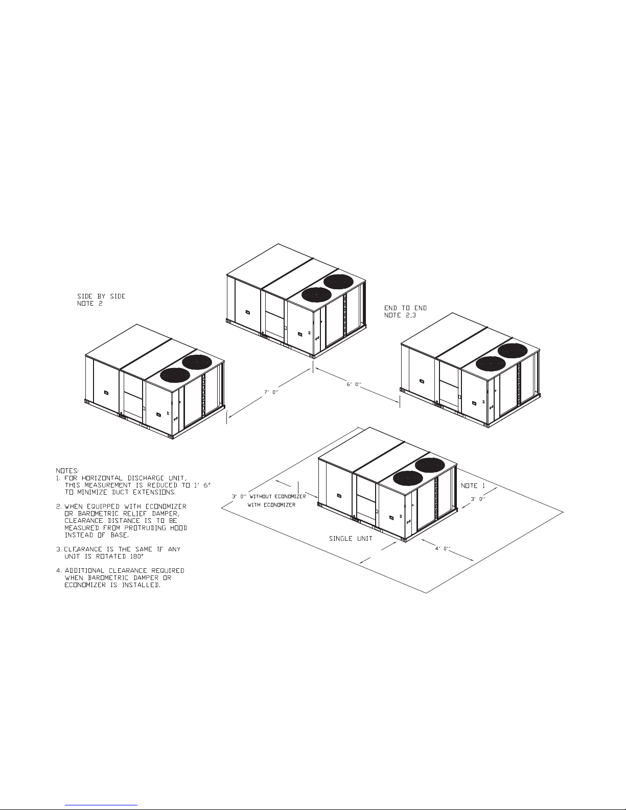
Figure 1, p. 12 illustrates the minimum operating and
service clearances for either a single or multiple unit
installation. These clearances are the minimum distances
necessary to assure adequate serviceability, cataloged
unit capacity, and peak operating efficiency.
Providing less than the recommended clearances may
result in condenser coil starvation, “short-circuiting” of
exhaust and economizer airflows, or recirculation of hot
condenser air.
Figure 1. Typical installation clearance for single and multiple unit applications
RT-SVX50C-EN 9
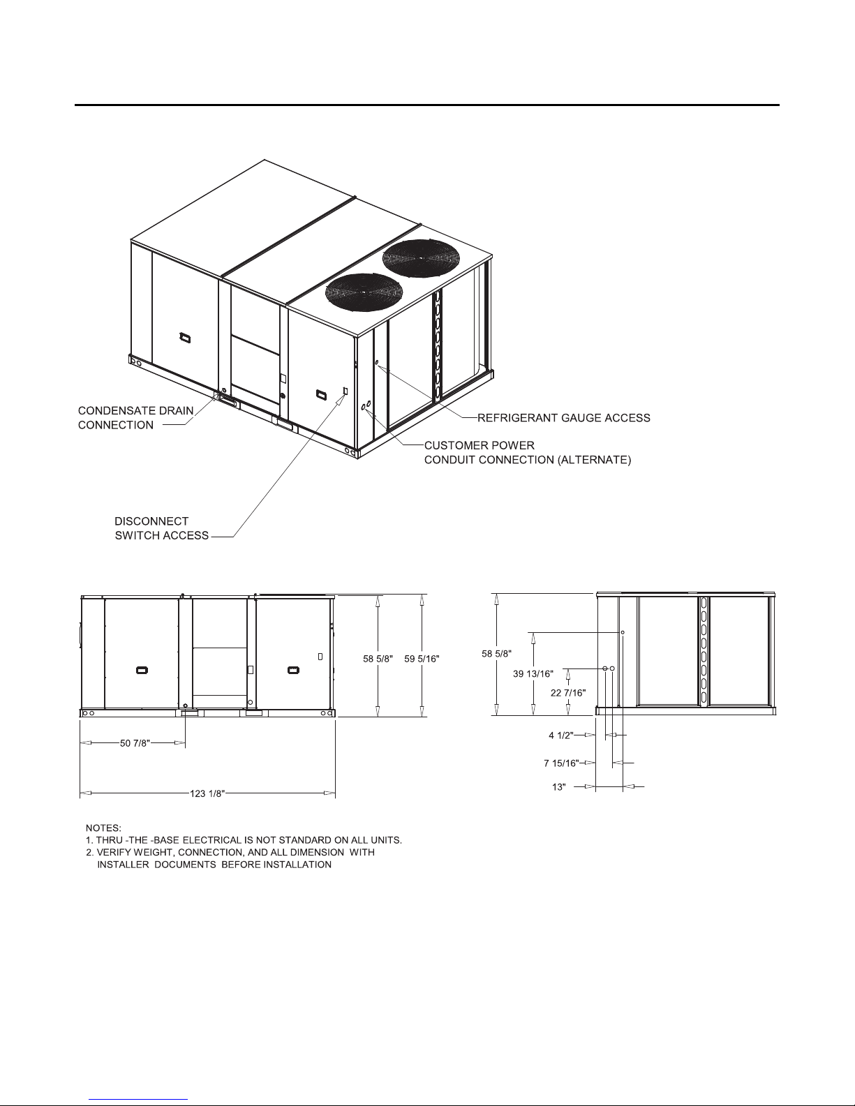
Dimensional Data
Figure 2. Cooling with optional electrical heat units — overview
Figure 3. Cooling with optional electrical units — front & side views — 15–25 tons standard efficiency
10 RT-SVX50C-EN
 Loading...