

Ingersoll-Rand DXR Series, DXR800, DXR1000, DXR425, DXR600 Operator's Instruction Manual
DXR SERIES
REFRIGERATED AIR DRYERS
OPERATOR'S
INSTRUCTION MANUAL
DXR425
DXR600
DXR800
DXR1000
English: 1-1
Español: 2-1
Before installation or starting the dryer for the
first time, study this manual carefully to obtain
a clear knowledge of the dryer and of the
duties to be performed while operating and
maintaining the dryer.
RETAIN THIS MANUAL WITH DRYER.
This technical manual contains IMPORTANT
SAFETY DATA and should be kept with the
dryer at all times.
Bulletin 553 Revision M (2/00)
Copyright ©2000 Ingersoll-Rand Company
Printed in USA

Table of Contents
INTRODUCTION ...............................1-1
SAFETY ....................................1-1
Safety Instructions ............................1-1
Safety Labels ...............................1-1
Data Plate and Labels ..........................1-1
RECEIVING AND INSPECTION ......................1-1
INSTALLATION ...............................1-2
Ambient Air Temperature ........................1-2
Location and Clearance .........................1-2
System Arrangement ...........................1-2
Piping and Connections .........................1-2
Drains ..................................1-2
Electrical Connections ..........................1-2
Cooling Water ..............................1-2
Air-Cooled Models............................1-3
HOW IT WORKS ...............................1-3
Air Flow .................................1-3
Refrigeration System...........................1-3
INSTRUMENTATION ............................1-4
Power Signal ...............................1-4
System Operation Monitor ..........................1-4
AUTOMATIC DRAIN VALVES ......................1-7
ADV Adjustment.............................1-8
START-UP ...................................1-8
SHUTDOWN .................................1-8
MAINTENANCE ...............................1-9
General ..................................1-9
Daily Maintenance ............................1-9
Weekly Maintenance...........................1-9
Monthly Maintenance ..........................1-9
Service Due Indicator ..........................1-9
Returns to Manufacturer .........................1-9
Ambient Air Filter Replacement ....................1-10
Automatic Drain Valve Disassembly and Servicing ..........1-10
Prefilter Element Replacement .....................1-10
FIELD SERVICE GUIDE ..........................1-12
REPLACEMENT PARTS ..........................A-1
SCHEMATICS ................................A-1
INTRODUCTION
DXR Series refrigerated air dryers use mechanical re
frigeration to dry compressed air to pressure dew points
as low as 33°F-39°F. They deliver the required dew
point at specified inlet air temperature, pressure and air
flow. Any change in these operating conditions may af
fect performance. See Table 9 for rated capacity and
other dryer specifications.
To ensure continuing good performance and safe opera
tion of the dryer, everyone who installs, uses or main
tains it must read and carefully follow the instructions in
this manual.
-
-
SAFETY
DXR Series dryers are designed and built with safety as
a prime consideration; industry-accepted safety factors
have been used in the design. Each dryer is checked at
the factory for safety and operation. All necessary ad
justments are made before shipment.
Follow the maintenance schedules outlined in this manual for good performance and safe operation. Maintenance should be done only by qualified personnel with
proper tools.
Carefully read the following safety rules before proceeding with installation, operation or maintenance. The
rules are essential to ensure safe dryer operation. Failure
to follow these rules may void the warranty or result in
dryer damage or personal injury.
1. Do not install or try to repair a dryer that has been
damaged in shipment. See Receiving and Inspec
tion for instructions.
2. Compressed air and electricity have the potential to
cause personal injury or equipment damage. Before
doing any work on the dryer, be sure the electrical
supply has been locked and tagged and the internal
pressure of the dryer has been vented to the atmos
phere.
3. Do not operate the dryer at pressures or tempera
tures above the maximum conditions shown on the
data plate.
4. Always supply electrical power that complies with
the voltage shown on the data plate.
5. Do not readjust the dryer without factory authoriza
tion.
6. Work on the refrigeration system must be done
only by a competent refrigeration mechanic.
-
-
-
-
7. Use only manufacturer's genuine replacement parts.
The manufacturer bears no responsibility for haz
ards caused by the use of unauthorized parts.
-
Safety Instructions
-
-
-
Safety instructions in this manual are boldfaced for em
phasis. The signal words DANGER, WARNING and
CAUTION are used to indicate hazard seriousness lev
els as follows:
DANGER—Immediate hazard which WILL result in
severe injury or death.
WARNING—Hazard or unsafe practice which
COULD result in severe injury or death.
CAUTION—Hazard or unsafe practice which COULD
result in minor injury or in product or property damage.
-
-
Safety Labels
Dryer labels providing important safety information are
included in this manual near corresponding text. If any
of the labels is missing or damaged, contact your local
distributor, request the label by its part number and apply it to the dryer.
Data Plate and Labels
The dryer data plate and dryer labels contain critical
safety and identification information. If any label or
data plate is missing or damaged, contact your local distributor and request a replacement.
RECEIVING AND INSPECTION
Inspect the dryer closely when it is received. Record
any indication of damage on the delivery receipt, espe
cially if the dryer will not be immediately uncrated. Ob
tain the delivery person's signed agreement to recorded
damages to facilitate future insurance claims.
Since the dryer is shipped F.O.B. New Castle, Dela
ware, the manufacturer's responsibility for the shipment
ceases when the carrier signs the bill of lading.
If goods are received short or in damaged condition, no
tify the carrier and insist on a notation of the loss or
damage across the face of the freight bill. Otherwise no
claim can be enforced against the carrier.
If concealed loss or damage is discovered, notify your
carrier at once and request an inspection. This is abso
-
lutely necessary. Unless you do this the carrier will not
consider any claim for loss or damage. The carrier will
make an inspection and may grant a concealed damage
notation. If you give the carrier a clear receipt for goods
that have been damaged or lost in transit, you do so at
your own risk and expense.
-
-
-
-
-
DXR Series Dryers (Bulletin 553) 1-1

The manufacturer is willing to assist you in collecting
claims for loss or damage. Willingness does not make
the manufacturer responsible for collecting claims or re
placing material. Claim filing and processing is your re
sponsibility.
Compressed air systems commonly require filters to re
move compressor oils, particulates, condensed liquids
and other contaminants. When an oil-removal filter is
-
-
used, install the filter downstream of the DXR Series
dryer. At this location, the life of the replaceable filter
element is prolonged since some of the entrained oil is
removed by the dryer and drained through the separator.
INSTALLATION
Ambient Air Temperature
Locate the dryer indoors where the ambient air tempera
ture will be between 40°F and 100°F. Intermittent op
eration at ambient temperatures up to 120°F will not
damage the dryer but may result in a higher dew point
or dryer shutdown due to high refrigerant discharge
pressure (see Field Service Guide). Call your local dis
tributor if prolonged operation at ambient temperatures
above 100°F or below 40°F is unavoidable.
Do not operate air-cooled dryers at ambient air tempera
tures below 40°F. Such operation may result in low suc
tion pressure, causing freeze-up.
Location and Clearance
Mount the dryer on a level base and bolt down if base
vibrates. If the dryer is air cooled, install it in a clean,
well-ventilated area to reduce fouling of the condenser
coils with dirt and dust. Allow 24 inches clearance on
the sides and front of the dryer for cooling airflow on
air-cooled dryers and for service access on both aircooled and water-cooled dryers.
System Arrangement
Liquid water adversely affects dryer performance. To
prevent “slugging” the dryer with liquid water, locate
the dryer downstream of an and a separator. Install
drain valves to discharge condensate that collects in
these areas.
If the airflow is relatively constant and will not cause
short term overloading of the dryer, it is recommended
that the dryer be located downstream of the receiver
tank. If the nature of the application is such that the air
demand regularly exceeds the dryer flow rating, it is
recommended that the dryer be located upstream of the
receiver.
For safety and convenience, install inlet and outlet shut
off valves and depressurization valves at the locations
indicated. These valves allow the dryer to be isolated
and depressurized for servicing. Bypass piping may be
installed around the dryer for uninterrupted airflow
when the dryer is serviced. If the compressed air opera
tion cannot tolerate undried air for short periods, install
a second dryer in the bypass line.
-
Piping and Connections
Piping must be furnished by the user unless otherwise
specified. Connections and fittings must be rated for the
maximum operating pressure given on the dryer data
plate and must be in accordance with applicable codes.
Support all piping; do not allow the weight of any pip
-
ing to stress the dryer or filters. Proper sizing of piping
-
should be determined using good engineering practice.
See Table 8 for dryer inlet and outlet connections.
Drains
Condensate must be drained from the dryer to prevent
its reentrainment. The dryers are equipped with an auto
matic drain valve. A condensate hose is coiled and secured inside the dryer cabinet for shipping. Uncoil the
hose and run it to a waste disposal collection system
that meets applicable regulations. Install the discharge
lines so that condensate can be seen as it drains.
Pipe or copper tubing
densate discharge lines. Do not use
1
-inch is recommended for con-
2
1
-inch or
4
5
16
-inch
O.D. flexible tubing unless the discharge line is shorter
than 10 feet.
Electrical Connections
Standard models are constructed according to NEMA
Type 1 electrical standard. Field wiring must comply
with local and national fire, safety and electrical codes.
Installation must be in accordance with the National
Electrical Code. Confirm that your line voltage is the
same as the voltage listed on the data plate.
Dryers are wired so that the crankcase heaters (if sup
plied) and drain valves are energized when power is
supplied, even if the power switch is turned off. See the
electrical schematics for wiring details.
Cooling Water
-
-
Water-cooled condensers are optional on some models.
The suffix W on the model number indicates watercooled. The user is responsible for piping the water to
and from the condenser. A factory-installed water regu
lating valve in the condenser inlet connection is stan
-
dard.
Required water flow rate depends on water temperature
(refer to Table 1). The valve supplied with the dryer
automatically adjusts the flow to compensate for varia
-
-
1-2 DXR Series Dryers (Bulletin 553)
tions in water temperature, water pressure and dryer air
load.
Operating the dryer with inadequate condenser cooling
water (temperatures above or pressures below those in
Table 1) will cause a rise in dew point unless the dryer
inlet airflow is reduced. The refrigerant discharge pres
sure control will shut down the refrigerant compressor if
cooling water is inadequate.
If the cooling water is dirty, install a strainer ahead of
the condenser inlet. Install shutoff valves so that the
strainer can be drained and cleaned at regular intervals.
COOLING WATER REQUIREMENTS
DRYER
MODEL
DXR425-W
DXR600-W
DXR800-W
DXR1000-W
a
Minimum water pressure is 25 psig for city water and 35 psig for
tower water. Maximum water pressure is 150 psig.
WATER
CONN.
(in NPT)
3
3
1
1
Table 1
COOLING WATER
REQUIRED
60°F 70°F 80°F 85°F 90°F
GPM GPM GPM GPM GPM
8
8
2
2
0.6 1.0 2.1 2.7 4.2
1.6 2.0 2.8 3.8 5.5
1.5 2.0 3.7 5.4 10.0
2.5 3.0 4.5 5.7 9.0
a
Air-Cooled Models
Cooling air must be drawn from a clear, well-ventilated
area to reduce dust and dirt accumulation on the condenser coils. Air temperature should not exceed 100°F.
Required air flow rates are shown in Table 2.
COOLING AIR REQUIREMENTS
MODEL
DXR425 3000
DXR600 2700
DXR800 5200
DXR1000 4800
Table 2
COOLING AIR
(cfm)
The cold, dry air is reheated by incoming warm air as it
passes back through the air-to-air heat exchanger. Using
the outgoing air to pre-cool the inlet air condenses up to
65 percent of the moisture out of the inlet air before it
reaches the chiller. Pre-cooling the inlet air reduces the
heat load on the refrigerant compressor, permitting the
use of a smaller refrigerant compressor.
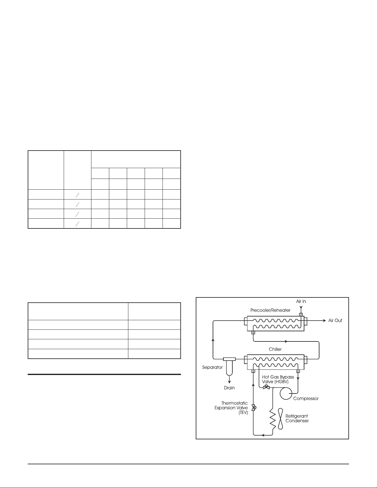
Refrigeration System
The refrigeration system is designed and fabricated in
accordance with recognized commercial/industrial prac
tices. It consists of a compressor and the controls, safety
interlocks and associated equipment necessary for safe
performance.
A thermostatic expansion valve (TEV) and a hot gas by
pass valve (HGBV) are used to modulate the refrigerant
flow. The TEV adjusts the flow of liquid refrigerant to
the chiller. A temperature sensor downstream of the
chiller opens and closes the TEV in response to the tem
perature of the refrigerant leaving the chiller to maintain
the proper cooling rate under all load conditions. The
HGBV delivers hot refrigerant gas to the chiller in response to changes in refrigerant pressure. This prevents
icing in the chiller and short cycling in the refrigerant
compressor during extended periods of system operation at low load.
All refrigerant valves are adjusted at the factory; operation is fully automatic.
-
-
-
HOW IT WORKS
Air Flow
DXR Series dryers use refrigeration cooling to condense
entrained moisture out of the airstream (see Figure 2).
Warm saturated air enters the air- to-air heat exchanger
where it is cooled by outgoing cold air. The inlet air is
further cooled in the refrigeration chiller. Cooling con
denses entrained moisture. The condensate is removed
by a centrifugal separator and an automatic drain valve.
DXR Series Dryers (Bulletin 553) 1-3
-
Figure 2.
Air and refrigerant flow schematic.
INSTRUMENTATION
Power Signal
All dryers are equipped with an ON-OFF switch located
on the front panel. A white light signals when power is
on.
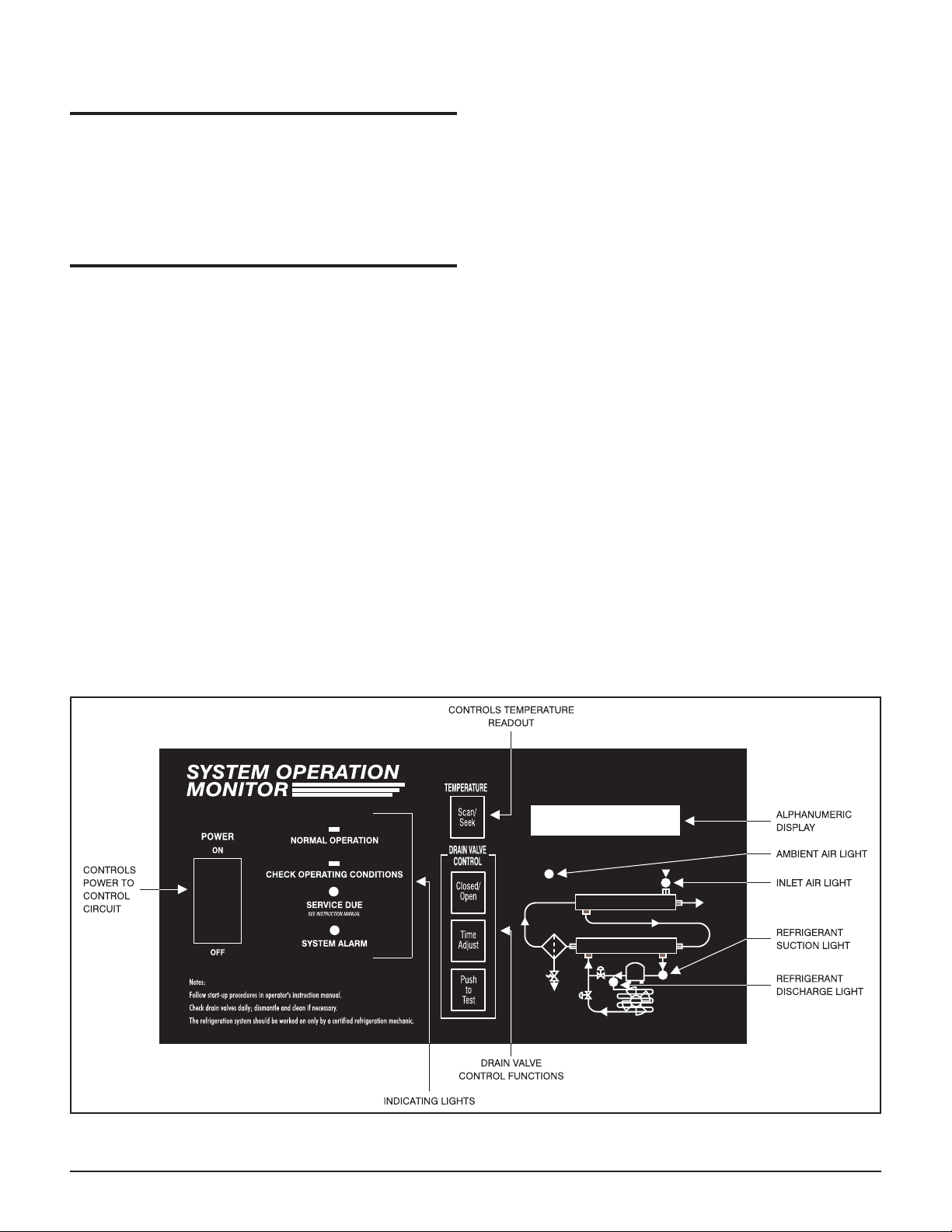
System Operation Monitor
A System Operation Monitor measures and displays
critical air and refrigerant temperatures, signals operat
ing conditions which may affect dryer performance, and
enables panel adjustment of the automatic drain valve.
There is also a light to indicate the need for routine
service.
The monitor consists of (refer to Figure 4):
indicating lights
•
alphanumeric display
•
• controls (push buttons) that provide access to
critical air and refrigerant temperatures
• schematic with lights that correspond to the
locations of the temperature sensors in the system
• drain valve controls
• temperature sensor probes
-
Indicating lights
The System Operation Monitor has four indicating
lights: NORMAL OPERATION, CHECK OPERAT
ING CONDITIONS, SERVICE DUE and SYSTEM
ALARM. Table 3 provides instructions for using the in
dicating lights to monitor dryer operation .
NORMAL OPERATION—The green NORMAL OP
ERATION indicator will light when the temperature in
side the evaporator (chiller) is normal.
CHECK OPERATING CONDITIONS —The red
CHECK OPERATING CONDITIONS indicator will
light when the temperature inside the evaporator is too
high.
SERVICE DUE—The yellow SERVICE DUE indica
tor will light under two conditions: as a reminder to per
form routine maintenance after 4,500 hours of dryer
service (approximately six months) and when a tem
perature sensor probe fails.
SYSTEM ALARM—The red SYSTEM ALARM indi
cator signals air system or dryer operating conditions
that may affect dew point performance or cause damage
to the dryer.
Temperature SCAN/SEEK push button
The SCAN/SEEK push button on the System Operation
Monitor provides a readout on the alphanumeric display
of the following temperatures:
-
-
-
-
-
-
-
-
• inlet air
System Operation Monitor
Figure 4.
1-4 DXR Series Dryers (Bulletin 553)
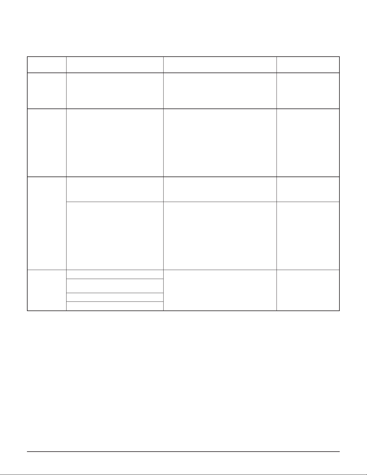
INDICATING
LIGHT
NORMAL
OPERATION
CHECK
OPERATING
CONDITIONS
SERVICE
DUE
SYSTEM
ALARM
SYSTEM OPERATION MONITOR INDICATING LIGHTS
INDICATES ACTION REQUIRED NOTES
The temperature inside the evaporator
(chiller) is normal.
The temperature inside the evaporator
(chiller) is too high.
1. 4,500 hours of dryer service
(approximately six months) has
passed; routine maintenance should
be performed.
2. A temperature sensor probe is
sensing temperature outside of normal
range or probe has failed. The probe
may sense temperatures outside of
normal range for up to two minutes
after startup or in extreme temperature
conditions. (The alphanumeric display
will read T1, T2, T3, T4 or T5
MALFUNCTION. T1 = inlet air, T2 =
refrigerant suction, T3 = refrigerant
discharge, T4 = ambient air, T5 =
evaporator.)
1. Inlet air temperature is too high.
2. Refrigerant suction temperature is
too low.
3. Ambient air temperature is too low.
4. Ambient air temperature is too high.
Table 3
This indicator should light within 30 minutes
of start-up, after the refrigeration system has
stabilized. It should remain on when the dryer
is operating.
It is normal for this light to be on when the
dryer is first turned on and remain on until
dryer has reached normal operating
temperatures (about 30 minutes).
If the CHECK OPERATING CONDITIONS
indicator turns on during normal operation,
turn the dryer off to avoid compressor
damage. Have a refrigeration mechanic
identify and correct the malfunction. If the
dryer is under warranty, call your local
distributor for authorization before servicing
1. See maintenance section in this manual for
further instructions.
2. Check sensor probe. Replace if necessary.
Determine which temperature(s) is out of
range. See Table 5 and the Field Service
Guide in this manual for possible
causes/remedies
Indicator will go off if the
CHECK OPERATING
CONDITIONS indicator
comes on or when a
temperature sensor
probe has failed.
Indicator will remain
illuminated until
problem has been
corrected.
See maintenance
section in this manual
for instructions on
resetting indicator.
Indicator will go off
when the dryer is turned
off. This will not affect
the 4,500 hour routine
maintenance indicator.
Indicator will not stop
flashing until the
problem has been
corrected.
•
refrigerant suction
•
refrigerant discharge
•
ambient air
The display can be programmed to automatically scan
each temperature for five seconds in sequence or to con
tinuously display any selected reading. The correspond
ing light on the system schematic will illuminate when
the temperature is displayed.
To scan the temperatures (normal mode): press and
hold the SCAN/SEEK button for three seconds. Each
temperature will then be displayed for five seconds in
the following sequence: inlet air, refrigerant suction, re
frigerant discharge and ambient air. To stop the scan
-
-
To display any selected temperature (seek/test
mode): press the SCAN/SEEK button once. The display
will read the same temperature until the button is
pressed again. When in seek mode, it will continue to
monitor for abnormal conditions.
-
Critical Air and Refrigerant Temperatures
Table 4 provides the normal range for each displayed
temperature when the dryers are operated in accordance
with specified conditions. If a temperature reaches the
warning set point indicated in the table, the correspond
ing light on the system schematic will flash during the
5-second display. If the temperature reaches the alarm
set point indicated in the table, the System Alarm indi
cator will flash. Refer to the Field Service Guide in this
-
mode push the TIME ADJUST button once.
DXR Series Dryers (Bulletin 553) 1-5
-
manual if any temperature readout falls outside the nor
mal range.
Inlet Air Temperature—If the inlet air temperature
falls outside the normal range, the dryer may fail to
achieve the required dew point. Check the compressor
aftercooler and adjust aftercooler operation to ensure
specified inlet air temperature to the dryer.
Refrigerant Suction Temperature—If the dryer has
been operating for more than 20 minutes and the refrig
erant suction light flashes, there may be a malfunction
in the refrigeration system. Turn the dryer off and have
a refrigeration mechanic identify and correct the mal
function. If the dryer is under warranty, call your local
distributor for authorization before servicing.
Refrigerant Discharge Temperature—This tempera
ture is used by service personnel to analyze the perform
ance of the refrigeration system.
-
able range, the dryer may fail to achieve the required
dew point or dryer shutdown may result due to high re
-
frigerant temperature.
Intermediate Air Temperature
This temperature is used by service personnel to analyze
the performance of the refrigeration system. Intermedi
ate air temperature is displayed by putting monitor in
Scan mode then pushing and holding down the TIME
-
ADJUST and CLOSED/OPEN buttons simultaneously
for three seconds. The intermediate air temperature will
be displayed for 5 seconds. The digital display will then
return to its last temperature readout.
Intermediate air temperature varies with operating con
ditions and ambient air temperature. Table 5 lists ap
-
proximate normal ranges of this temperature at various
inlet flows and dew point classes.
-
-
-
Ambient Air Temperature—If the ambient air tem
perature falls outside the acceptable range, the dryer
may fail to achieve the required dew point or dryer shutdown may result due to high refrigerant discharge pressure.
Inlet Condensing Water Temperature (Water-cooled
models) — If the cooling water falls outside the accept-
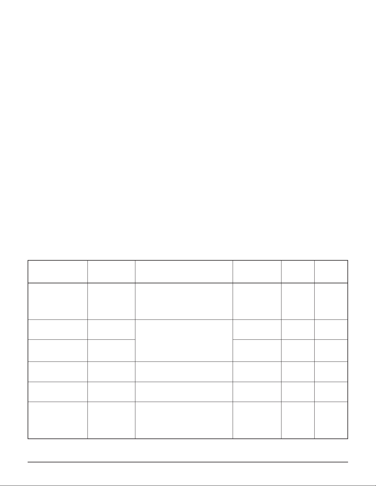
AIR AND REFRIGERANT TEMPERATURES
DIGITAL
DISPLAY
Inlet Air Inlet air piping
Refrigerant
Suction
Refrigerant
Discharge
Ambient Air
(Air-Cooled Only)
Inlet Condensing
Water
(Water-Cooled Only)
Intermediate Air
a
Normal temperature range is indicated by a 3-second red light. The red light flashes when temperatures are outside the normal range.
Dew points 50°F or higher may cause the REFRIG. SUCTION signal to flash. See the Field Service Guide if red lights flash.
TEMPERATURE
PROBE
LOCATION
Refrigerant line
upstream of
compressor
Refrigerant line
downstream of
compressor
Outside the
condenser
Inlet pipe of the
condenser
Outside surface
of chiller
discharge
piping
Inlet air temperature varies with
changes in aftercooler cooling
medium temperature and air
compressor unloading. Inlet
temperatures higher than 100°F
reduce drying capacity.
These refrigerant temperatures vary
with the refrigeration load and are
controlled by refrigeration valve
settings. These readings are used
primarily by service personnel to
analyze refrigeration system
performance.
Ambient air temperatures higher
than 100°F will reduce drying
capacity.
Cooling water temperatures in
excess of 100°F will reduce drying
capacity.
Intermediate air temperature varies
with inlet air pressure, ambient
temperature and airflow. This
reading is used primarily by service
personnel to analyze refrigeration
system performance.
Table 4
COMMENTS
NORMAL
TEMPERATURE
RANGE
40°F – 120°F >115°F >120°F
32°F – 55°F N.A. 25°F
140°F – 240°F N.A. N.A.
35°F – 120°F
35°F – 120°F
Variable;
see Table 5
a
WARNING
SET
POINT
> 115°F/
< 35°F
> 115°F/
< 35°F
N.A. N.A.
ALARM
SET
POINT
> 120°F/
< 35°F
> 120°F/
< 35°F
1-6 DXR Series Dryers (Bulletin 553)
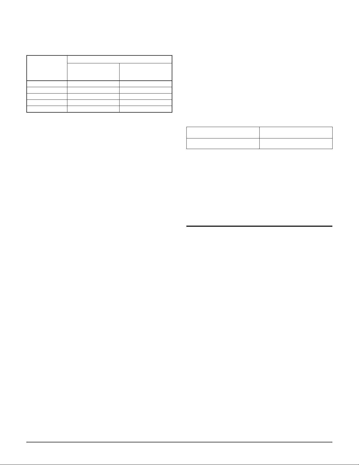
INTERMEDIATE AIR TEMPERATURE
DRYER INLET
AIRFLOW
(% of rated
capacity)
80 - 100 35°F - 45°F 50°F - 60°F
50 - 79 45°F - 55°F 60°F - 70°F
25 - 49 55°F - 65°F 70°F - 80°F
10 - 24 65°F - 75°F 80°F - 90°F
No airflow 75°F - 100°F 90°F - 100°F
a
Based on 90°F - 100°F dryer inlet air temperature and 100°F ambient
air temperature. These ranges are approximate and may vary with
changes in inlet air pressure, ambient temperature and inlet airflow.
Table 5
APPROXIMATE NORMAL RANGE
33°F - 39°F
Dew Point
50° - 54°F
Dew Point
a
RS-232 Serial Port
The RS-232 serial communications port allows for mon
itoring of current temperature and error flags. Commu
nication is via a series of ASCII characters sent every
second. The data format is shown below. The baud rate
is 4800, 8 bits, no parity.
Message format:
DS version:
:Ixxx,Sxxx,Dxxx,Axxx,Oxxx,Nxxx,Lyy,Syy<cr><lf>
•
Where:
** Intermediate or Glycol is displayed, based on
version.
The alarm bits are preceded with either:
L = Alarm bits
•
S = Service Due indication
•
The HEX characters that follow “L” or “S” convey an
eight-bit field which indicates the source of the alarm or
service due indicator. A value of all zeros (0x00) indi
-
cates that no alarm or service due condition exists.
Version Program
-
1
-
svc = > 4500 hours operating time
DS inlet
Remote Alarm Contacts (Optional)
Dry (unpowered) contacts including one normally open
set and one normally closed set are provided to signal
remote indication if the CHECK OPERATING CON
DITIONS or SYSTEM ALARM indicators are activated. The contacts are 2½ Amps max., unfused and
120/240 VAC max.
• “:” = colon character
• “,” = comma character
• <cr> = carriage return
• <lf> = line feed
•
xxx = temperature in BCD, leading zeros are sup
pressed (replaced with spaces. Out-of-range val
ues are displayed as “---”.)
•
yy = alarm bits in ASCII HEX format
Each numerical temperature value is preceded with a
single alphabetic identifier:
•
I = Inlet air
•
S = Suction
•
D = Discharge
•
W = Water*
•
A = Ambient*
•
O = Operation
•
G = Glycol**
•
N = Intermediate**
* Water or Ambient is displayed, based on ver
sion.
AUTOMATIC DRAIN VALVES
All dryers are equipped with an electronic drain valve
that automatically discharges condensate from the dryer.
Drain valve controls are on the system operation monitor. The ADV controls allow the period of drain open-
-
-
-
ing to be set from 1 second to 10 seconds and the drain
closed (cycle) time to be set from 0.5 minutes to 10
minutes. A test push button helps to check ADV opera
tion. When the button is pushed, the drain port clicks
open with a clearly audible sound.
To set the drain closed (cycle) time:
The monitor must be in the Scan mode. Press the
CLOSED/OPEN button once. The display will show the
current setting for the ADV closed time.
Press and hold the TIME ADJUST button. Release the
button when the display reads the desired time. The se
-
lected time will be locked into memory.
To set the drain open time:
The monitor must be in the Scan mode. If monitor is not
already in the mode for adjusting drain closed time,
slowly push the CLOSED/OPEN button once. Allow a
few seconds for monitor to set up, then push the button
a second time. The display will show the current setting
for the ADV open time.
-
DXR Series Dryers (Bulletin 553) 1-7

Press and hold the TIME ADJUST button. Release the
button when the display reads the desired time. The se
lected time will be locked into memory.
-
ADV Adjustment
To minimize air losses, the ADV timer should be ad
justed to open the drain port just long enough to dis
charge accumulated condensate. Set the timer so that
only air discharges at the end of the open period. Rec
ommended initial settings are a 3-second drain opening
and a 3-minute drain closed time (cycle). The separator
or filter bowl is likely to fill with water if the drain cy
cle is too long. If liquid discharges as the port is closing,
set the timer for a shorter cycle or a longer opening.
-
-
-
-
START-UP
Follow the procedure below to start your dryer. Failure
to follow the prescribed start-up procedure will invali
date the warranty. If problems arise during start-up, call
your local distributor.
Before you start the dryer:
1. Turn off the dryer ON/OFF switch.
2. Verify the main electrical supply voltage matches
the voltage specified on the dryer data plate.
3. Turn on the main electrical power to the dryer.
The crankcase heater is wired to be on when power
is supplied to the dryer. The crankcase heater
must be warmed up for 4 hours before starting
the dryer. This warm-up heats the compressor
oil and boils off liquid refrigerant to prevent
damage to the compressor.
During the warm-up period:
•
Do not turn the dryer switch on.
•
Compressed air may flow through the dryer dur
ing warm-up but drain valves will not be func
tional.
After the main electrical power to the dryer has
been on for 4 hours, the dryer may be started.
To start the dryer:
-
-
-
a collection tank or an environmentally-approved
disposal system.
3. Check ADV timing. See Automatic Drain Valve
section for ADV adjustment procedure.
4. Check customer-supplied circuit breakers or fuses.
Reset or replace as required.
5. Check proper connection and support of com
pressed air lines to the dryer; check bypass valving
system, if installed.
6. Ensure adequate ventilation for air-cooled dryers.
7. For water-cooled models, verify the water supply is
connected to the water regulating valve on the con
denser. Confirm that the cooling water supply
meets the required flow and temperature (see Table
1).
8. Confirm that the inlet air temperature, pressure and
airflow to the dryer meet the specified requirements
(see Tables 8 and 9).
9. After 30 minutes of operation, check the CHECK
OPERATING CONDITIONS indicator. If this indicator is lit, turn the dryer off and call your local
distributor.
10. If the CHECK OPERATING CONDITIONS indicator has turned off after 30 minutes of operation,
check the following temperatures on the System
Operation Monitor:
• Refrigerant discharge (head) temperature should
be within the range of 140°F to 220°F.
•
Refrigerant suction temperature should be within
the range of 32°F to 55°F.
If either temperature is out of range, see the Field
Service Guide for correction.
The dryer is designed to run continuously. Let the dryer
run even when the demand for compressed air is inter
rupted; the dryer will not freeze up. If the supply power has
been turned off for more than four hours, supply power to
the dryer; warm up the crankcase heater (if applicable) for
4 hours before starting the dryer to vaporize any accumu
lated liquid refrigerant from the compressor oil.
-
-
-
-
1. Turn the power switch to ON. The refrigerant com
pressor will turn on. The monitor will turn on and
the CHECK OPERATING CONDITIONS indica
tor may turn on. If the dryer does not start in this
way, call your local distributor.
2. Confirm that condensate is discharging from the
automatic drain valves and that the condensate
lines from the automatic drain valve discharge into
1-8 DXR Series Dryers (Bulletin 553)
-
SHUTDOWN
When the dryer must be shut down for maintenance or
other reasons, use the following procedures.
If electrical repairs must be made:
1. Turn off the power switch.
2. Disconnect the main power supply.
3. Lock out and tag the power supply in accordance
with OSHA requirements.
Refer to the Instrumentation section and the Field Serv
ice Guide for further information.
-
DANGER
Portions of the control circuit remain
energized when the power switch is in the OFF
position. Disconnect supply powerto the dryer
before performing maintenance on the
electrical system.
If mechanical repairs must be made, vent the internal
pressure of the dryer to atmospheric pressure.
Restart the dryer according to the start-up instructions.
MAINTENANCE
DXR Series dryers require little maintenance for satis
factory operation. Good performance can be expected if
the following routine maintenance steps are taken.
DANGER
Dismantling or working on any component of
the compressed air system under pressure
may cause equipment failure and serious
personal injury. Before dismantling any part of
the dryer or compressed air system,
completely vent the internal pressure to the
atmosphere.
General
For continued good performance of your refrigerated
dryer, all refrigeration system maintenance should be
performed by a competent refrigeration mechanic. Bef
ore corrective maintenance is done during the warranty
period, call your local distributor and proceed according
to instructions. Refer to the warranty for limits of your
coverage.
Daily Maintenance
Check the operation of the automatic drain valve at least
once during each 8-hour shift. See the Field Service
Guide for remedies to drain valve malfunctions. See the
Instrumentation section for drain valve adjustment.
Check the following readouts on the system operation
monitor.
•
high evaporator temperature
•
refrigerant suction temperature
•
refrigerant discharge temperature
•
alarm lights
-
-
Weekly Maintenance
Check prefilter (if installed) differential pressure gauge.
Replace filter element when pointer reaches red zone of
gauge (approx. 7 to 10 psid). Failure to change element
at least once a year or when the gauge reaches the red
zone will adversely affect dryer performance. See Filter
Element Replacement procedure.
Monthly Maintenance
For air-cooled condensers, inspect the condenser coils.
Remove dust, dirt or other particles with a soft brush or
with compressed air from an OSHA-approved air nozzle
that limits its discharge pressure to 30 psig. If the coils
are coated with oil, grease or other substances that re
duce the cooling efficiency, clean the coil.
Replace the ambient air filter. See Ambient Air Filter
Replacement procedure.
-
Service Due Indicator
On dryers equipped with the System Operation Monitor,
the yellow SERVICE DUE indicator will light after
4,500 hours (six months) of dryer operation. At this
time, complete the following:
• Disassemble and clean automatic drain valve.
• Disassemble and clean separator bowl.
• For air-cooled condensers, inspect the condenser
coils; clean if necessary. Lubricate fan motors
with 20 wt motor oil (if necessary).
•
For water-cooled condensers, clean customersupplied strainer.
To reset the SERVICE DUE INDICATOR:
1. Turn the power switch to the OFF position.
2. Hold down the PUSH TO TEST and
CLOSED/OPEN buttons simultaneously.
3. Turn the power switch to the ON position.
4. Wait two seconds. Release the PUSH TO TEST
and CLOSED/OPEN buttons. The indicator is now
reset.
Returns to Manufacturer
If the dryer or a component of the dryer must be re
turned to the manufacturer, first call your local distribu
tor for a return authorization number and shipping
address. Your distributor will inform you whether the
dryer or only a component must be returned. Mark the
package with the return authorization number and ship
freight prepaid as directed by your local distributor.
-
-
DXR Series Dryers (Bulletin 553) 1-9
Ambient Air Filter Replacement
For units equipped with the optional ambient air filter
(designated by the suffix F in the model number), in
spect the filter element. If necessary, replace the ele
ment by lifting it out and slipping in a replacement. See
the replacement parts lists for replacement element
model numbers.
-
-
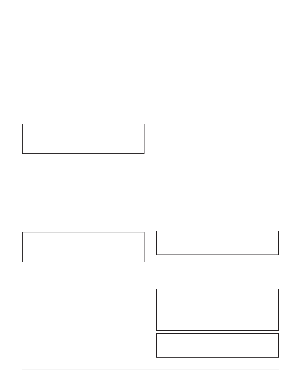
Automatic Drain Valve Disassembly and
Servicing
All DXR Series dryers have a timer-controlled auto
matic drain valve.The valve body is mounted on the
frame bottom; a hose connects the valve body to the
separator.
CAUTION
Do not disassemble drain valve timer or
attempt to repair electrical parts. Replace
timer if defective.
The drain valves discharge condensate through a
full-port drain opening.
The valve body may need to be cleaned under conditions of gross particulate contamination. To disassemble
the drain valve body for cleaning or other maintenance
(see Figure 6):
1. Turn power switch off.
2. Disconnect main power supply to dryer.
3. Lock out and tag power supply in accordance with
OSHA requirements.
-
Once the drain valve is disassembled, the following
maintenance can be performed.
1. Inspect diaphragm; clean or replace as required.
2. Remove debris from valve body.
3. Wipe solenoid core components with a clean cloth
or blow out debris with compressed air from an
OSHA-approved air nozzle that limits its discharge
pressure to 30 psig.
4. Check that small port in diaphragm assembly is
clear and solenoid coil moves freely in housing. Vi
ton diaphragm seals are compatible with commonly
used synthetic lubricants.
5. If timer is attached to valve body, check electrical
continuity across timer assembly.
To reassemble the drain valve, reverse the sequence of
the preceding steps. After the drain valve is reassem
bled, connect the main power supply to the dryer. When
the dryer is returned to service, check the drain valve for
air or condensate leaks; tighten connections as required
to correct leaks. Check the drain cycle; adjust the timer
according to the procedure in the Automatic Drain
Valve Adjustment section.
-
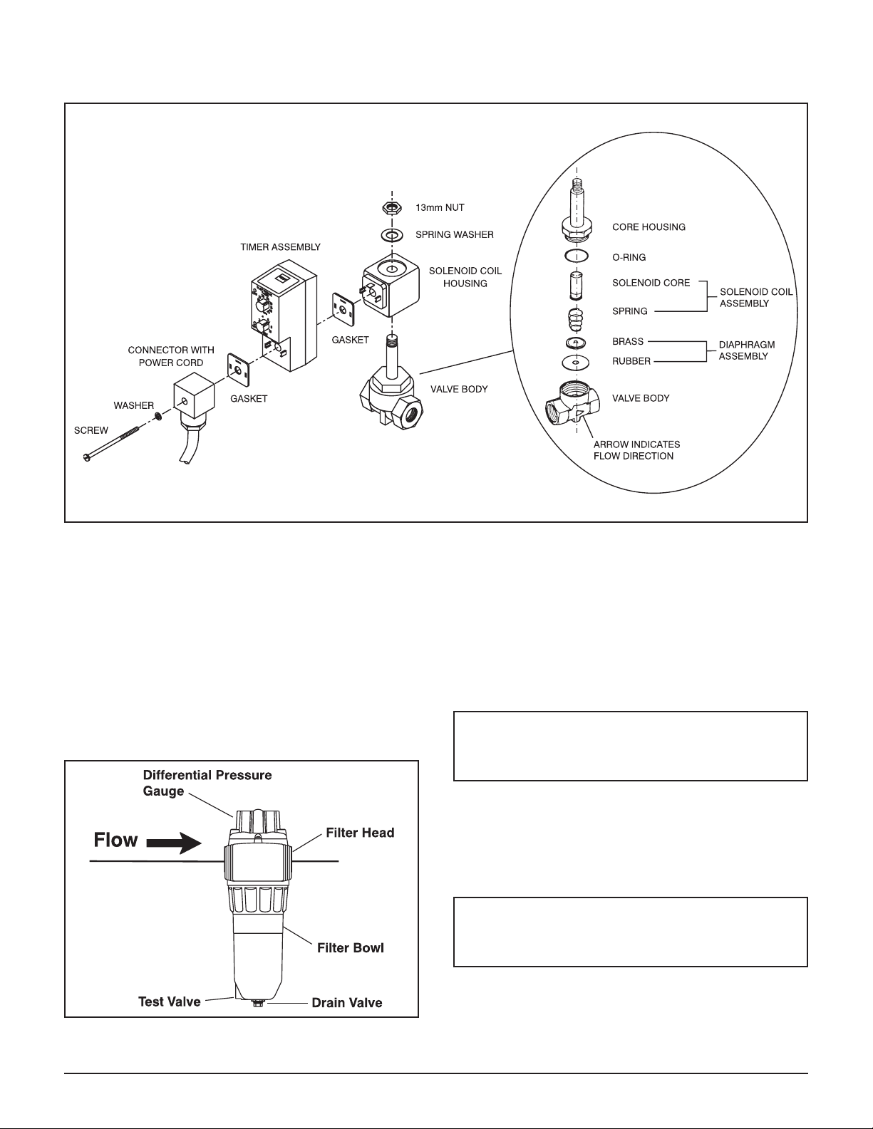
Prefilter Element Replacement
On models equipped with the cold coalescing option (C
option), the filter element must be replaced at least once
a year or when the differential pressure gauge on top of
the filter is in the red zone.
To replacing the coalescing prefilter element:
-
WARNING
If power supply is not disconnected before
disassembly, serious personal injury and
valve damage may result.
4. Remove hoses that connect the drain valve to the
separator.
5. Remove screw and washer from front of the drain
valve.
6. Remove the power supply connector and gasket
(with timer assembly if attached) from the solenoid
coil housing. Do not damage or lose the gasket.
7. Remove 13mm nut and spring washer from top of
solenoid coil housing.
8. Lift solenoid coil housing off solenoid core in valve
body.
9. Unscrew solenoid core from valve body.
1-10 DXR Series Dryers (Bulletin 553)
Vent internal pressure to atmospheric
pressure before performing anymaintenance.
1. Vent the internal pressure to the atmosphere. Refer
to the shutdown instructions on page 8.
2. Disconnect drain lines at manual and automatic
drain valves (if installed).
A “hissing” sound while the bowl is being
removed indicates the filter has not been
properly depressurized. DO NOT continue to
remove the bowl until the filter has been
completely vented to atmospheric pressure.
Filter bowls may be heavy. Caution should be
taken when removing the bowl.
DANGER
DANGER
CAUTION
Automatic Drain Valve Components
Figure 6
3. Remove the bottom bowl by unscrewing it from the
head. A strap wrench may be needed.
4. Remove the element from the filter head with a
brisk downward pull, or by working the element
back and forth until it snaps free. Discard the ele
ment in accordance with applicable regulations.
Used elements typically hold contaminants, such as
compressor lubricants and particulate matter.
Note: The element may be unsnapped by DPin
normal operation. This will not affect filtration,
as the O-ring on the element maintains a positive
seal.
5. Clean accumulated debris from the bowl with soap
and water, and dry thoroughly.
CAUTION
Lubricate the O-ring with a petroleum-based
lubricant compatible with your application.
6. Lightly lubricate the new element O-ring before in
stalling the new element.
7. Insert new element, snapping it into place with a
firm push up into the head. The element will hang
from the head until the bowl is installed.
CAUTION
Lubricate the O-ring with a petroleum-based
lubricant compatible with your application.
8. Lightly lubricate the filter bowl O-ring.
-
Side view of coalescing filter
DXR Series Dryers (Bulletin 553) 1-11
Figure 7
CAUTION
Do not use a pipe wrench to tighten the filter
bowl to the head.
9. Reattach bowl to head and hand tighten. As the
bowl is threaded onto the head, supports in the bot
tom of the bowl ensure a proper seal between the
element and the filter head.
10. Reattach drain lines (if applicable).
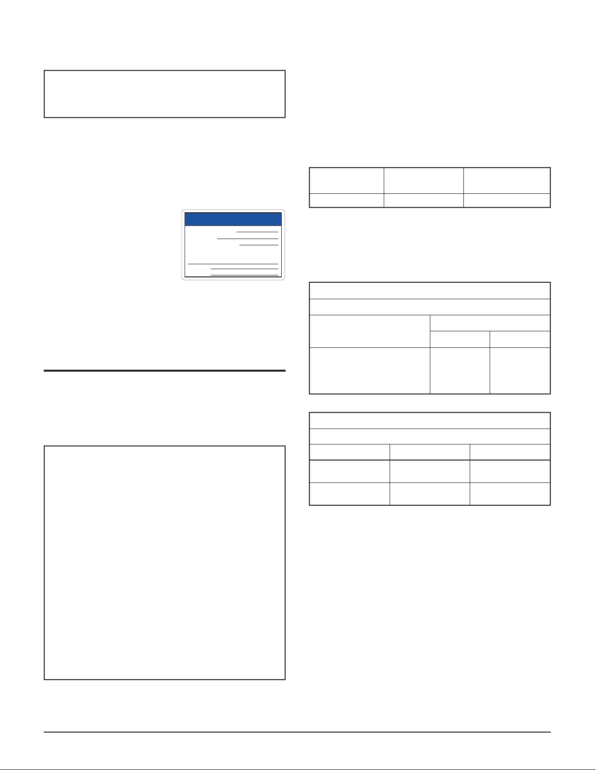
11. Record the date of the element change in a record
book or on the provided
“Maintenance Reminder”
label. The maintenance
reminder label with the
updated information
should be applied over
MAINTENANCE REMINDER
Date Element Changed:
Changed By:
Next Scheduled Change:
Additional elements available from your local
Ingersoll-Rand Compressed Air System supplier
Telephone:
Fax:
the previous label each
time the element is replaced.
Restart the dryer according to the Start-up instructions
on page 8.
FIELD SERVICE GUIDE
Problems most frequently encountered with refrigerated
dryers are water downstream of the dryer and excessive
pressure drop. Most causes can be identified and remedied by following this guide.
DANGER
Closed refrigeration systems are potentially
dangerous. Work on the refrigeration system
must be done only by a competent
refrigeration mechanic.
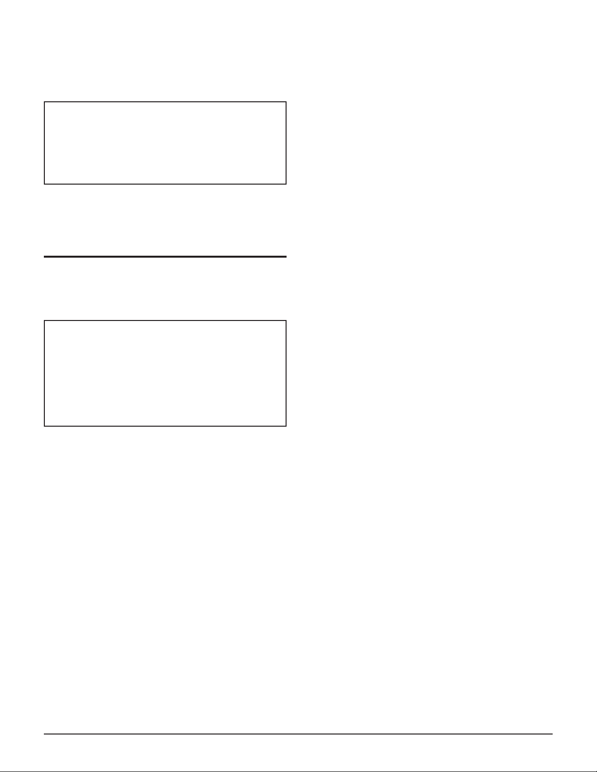
the dryer. While the dryer is operating, the suction pres
sure/temperature may fluctuate slowly with changes in
the refrigeration load. To determine the suction pres
sure/temperature, a refrigeration mechanic should attach
a set of gauges to the unit. Gauge readings should be as
follows:
-
SUCTION PRESSURE/TEMPERATURE
REFRIGERANT
R-22 58 psig/33°F 68 psig/40°F
Do not adjust refrigerant valves without factory authori
Table 6
WITHOUT
AIRFLOW
WITH
AIRFLOW
zation. Adjustments must be made only with no airflow
into the dryer.
REFRIGERANT PRESSURE SWITCH SETTINGS
Pressure Switch Setting
Model
DXR425
DXR600
DXR800
DXR1000
Refrigerant Compressor Control
Pressure Switch Setting
Sensor Location Cut out Cut In
Compressor
Discharge
Compressor
Suction
Table 7
Fan Cycle Control
R-22
On Off
275 195
405 280
40 60
Do not release fluorocarbon refrigerants
indoors; do not discharge liquid refrigerants
into floor drains. Refrigerant vapors may
accumulate in low places. Inhalation of high
concentrations may be fatal. All refrigerants
must be recovered per EPA requirements.
Do not smoke while working on the
refrigeration system or when a refrigerant leak
is suspected. Burning materials may
decompose refrigerants, forming toxic gas or
acids that may cause serious injury and
property damage.
The refrigerant valves are adjusted at the factory with
the refrigerant system operating and no airflow through
1-12 DXR Series Dryers (Bulletin 553)
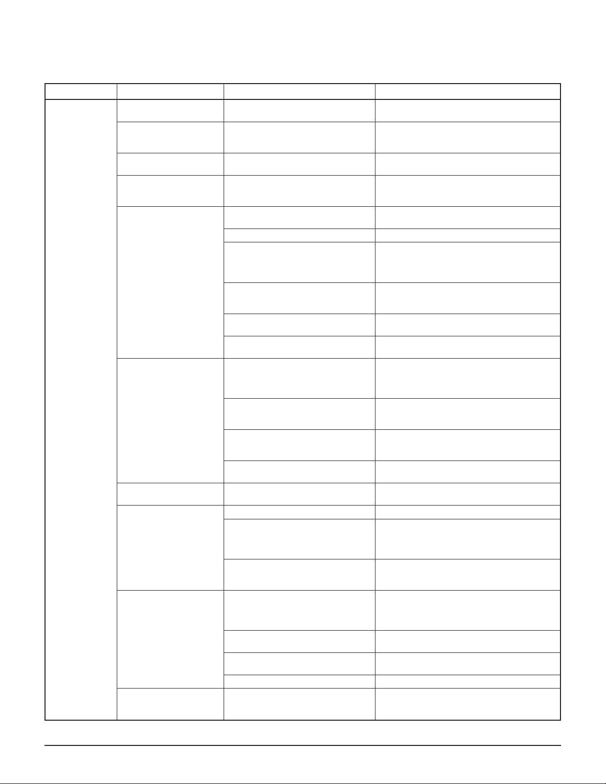
FIELD SERVICE GUIDE
PROBLEM SYMPTOM(S) POSSIBLE CAUSE REMEDY
No discharge from auto
matic drain valves.
Inlet air temperature is
outside normal range or
reaches alarm set point.
Liquid water entering
dryer.
Excessive airflow (may
also cause high pres
sure drop).
Drain valve failure or accumulation
of dirt in valve.
Dismantle drain valve; clean, repair or re
place. See Maintenance section.
Aftercooler malfunction. Check aftercooler discharge temperature.
Reduce temperature to 120°F max.; reduce
airflow if temperature is above 100°F.
Aftercooler drain valve malfunction. Dismantle aftercooler drain valve; clean, re
pair or replace.
Dryer improperly sized. Check airflow and dryer capacity (see Table
-
8). Reduce airflow or resize and replace
dryer.
1. Condenser fouled or clogged. 1. Clean condenser coils (see Mainte
nance, Monthly).
2. Fan motor stopped. 2. Repair or replace fan motor.
3. Inlet air temperature too high. 3. Check aftercooler discharge temperature.
Reduce temperature to 120°F max.; reduce
Refrigerant compressor
cut out by high
refrigerant discharge
pressure control.
4. Air in refrigeration system. 4. Have refrigeration mechanic locate and
airflow if temperature is higher than 100°F
(see Airflow section).
repair leak. Recharge. Refer to data plate for
refrigerant type and quantity.
5. Ambient air temperature too high
5. Vent compressor room to outside.
for air-cooled compressor.
6. Aftercooler coolant air blowing
6. Baffle or vent to outside air.
on air-cooled condenser.
1. Inadequate ventilation of aircooled compressor.
1. Ensure adequate ventilation of the condensing unit (see Clearance). Motor will restart automatically when compressor is
cool.
Water
downstream of
dryer.
Compressor cuts out
on internal overload.
2. Insufficient cooling water for
water-cooled compressor.
2. Ensure adequate cooling water (see Ta-
ble 1). Motor will re- start automatically
when compressor is cool.
3. Leak in refrigeration system. 3. Locate leak. Repair and recharge. Motor
will restart automatically when compressor
is cool.
4. Incorrect adjustment of refrigera
-
4. Call your local distributor.
tion control valves.
Compressor windings
read open or shorted.
Compressor burned out. Have refrigeration mechanic check and re
place.
1. Leak in refrigeration system. 1. Locate leak; repair and recharge.
2. Improper adjustment of HGBV. 2. Remove cap from HGBV and screw out
HIGH EVAP light on
or
Dew point indicator in
red zone
3. Air or noncondensables in refrig
eration system. Possible leak in
chiller.
HGBV ½-turn with an allen wrench to lower
suction temperature to the level listed in the
Refrigerant Flow section.
-
3. Locate leak; repair and recharge. If chiller
must be replaced, consult your local dis
tributor.
1. Improper adjustment of HGBV. 1. Remove cap from HGBV and screw out
HGBV ½-turn with an allen wrench to lower
suction temperature to the level listed in the
Refrigerant Flow section.
Suction temperature
higher than 65°F.
2. Inlet air temperature higher than
130°F.
2. Reduce aftercooler discharge tempera
ture to design conditions (120°F max.).
3. Excessive airflow 3. Check airflow and system capacity. Re
duce airflow or resize and replace system.
4. Leak in refrigeration system. 4. Locate leak; repair and recharge.
Refrigerant discharge
Low ambient temperature. Consult your local distributor.
temperature lower than
140°F.
-
-
-
-
-
-
-
DXR Series Dryers (Bulletin 553) 1-13
 Loading...