

Ingersoll-Rand CA200RS812, CA120RS812, CA200RS418, CA200RS818, CA120RS418 Operation And Maintenance Manual
...Page 1

TPD1680
03538154
Form P6958
Edition 7
May, 1999
F
E
OPERATION AND MAINTENANCE MANUAL FOR
P
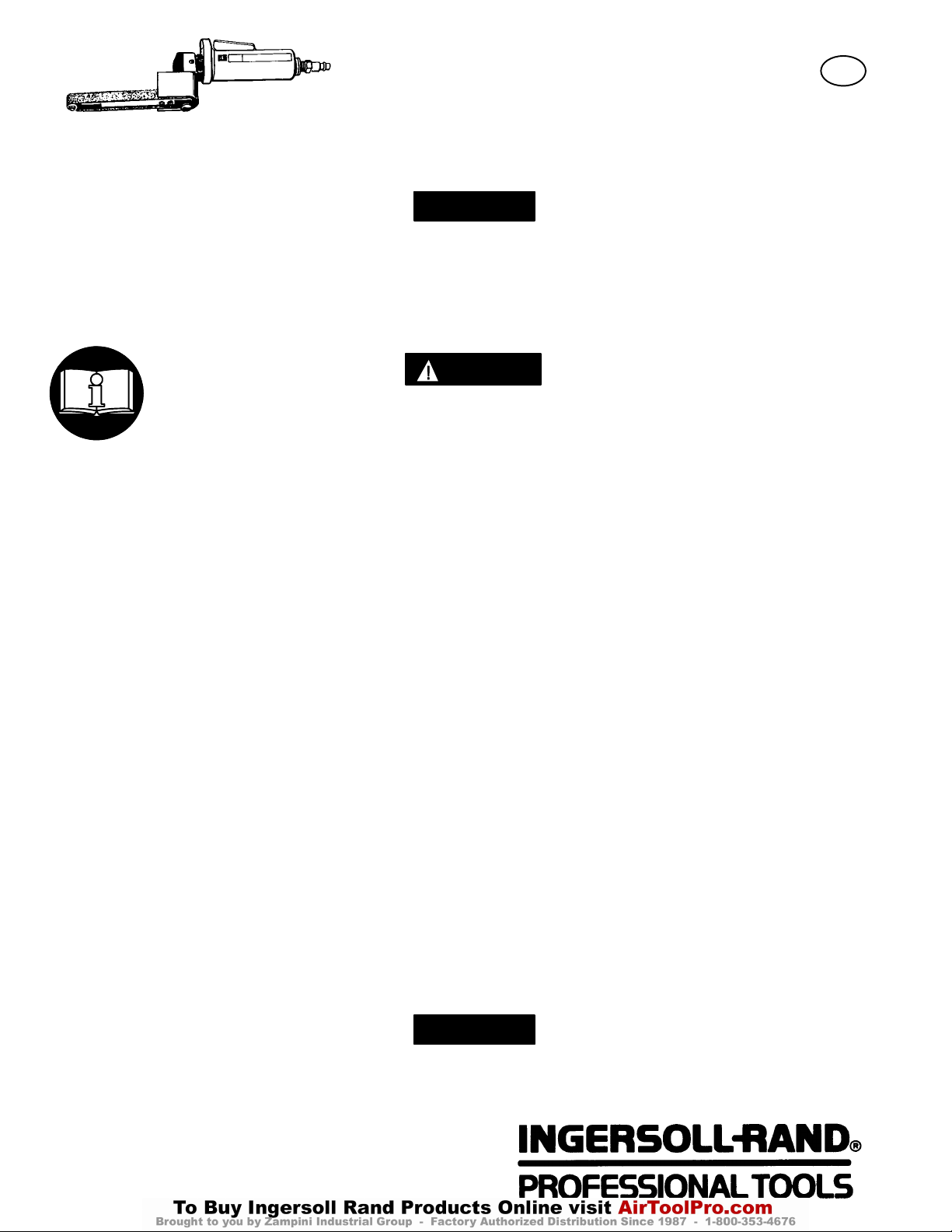
SERIES CA ANGLE BELT SANDERS
Series CA Angle Belt Sanders are designed for work in the metal fabricating industry
and foundry applications. These small Angle Belt Sanders are very efficient at grinding
weld bead, slag and parting lines while leaving a fine finish.
Ingersoll–Rand is not responsible for customer modification of tools for applications on
which Ingersoll–Rand was not consulted.
IMPORTANT SAFETY INFORMATION ENCLOSED.
READ THIS MANUAL BEFORE OPERATING TOOL.
IT IS THE RESPONSIBILITY OF THE EMPLOYER TO PLACE THE INFORMATION
IN THIS MANUAL INTO THE HANDS OF THE OPERATOR.
FAILURE TO OBSERVE THE FOLLOWING WARNINGS COULD RESULT IN INJURY.
PLACING TOOL IN SERVICE
• Always operate, inspect and maintain this tool in
accordance with American National Standards
Institute Safety Code for Portable Air Tools
(ANSI B186.1).
• For safety, top performance, and maximum
durability of parts, operate this tool at 90 psig
(6.2 bar/620 kPa) maximum air pressure at the inlet
with 5/16” (8 mm) inside diameter air supply hose.
• Always turn off the air supply and disconnect the
air supply hose before installing, removing or
adjusting any accessory on this tool, or before
performing any maintenance on this tool.
• Do not use damaged, frayed or deteriorated air
hoses and fittings.
• Be sure all hoses and fittings are the correct size
and are tightly secured. See Dwg. TPD905–1 for a
typical piping arrangement.
• Always use clean, dry air at 90 psig
(6.2 bar/620 kPa) maximum air pressure. Dust,
corrosive fumes and/or excessive moisture can ruin
the motor of an air tool.
• Do not lubricate tools with flammable or volatile
liquids such as kerosene, diesel or jet fuel.
• Do not remove any labels. Replace any damaged
label.
USING THE TOOL
• Always wear eye protection when operating or
performing maintenance on this tool.
• Always wear hearing protection when operating
this tool.
• Keep hands, loose clothing and long hair away from
rotating end of tool.
• Anticipate and be alert for sudden changes in
motion during start up and operation of any power
tool.
• Keep body stance balanced and firm. Do not
overreach when operating this tool. High reaction
torques can occur at or below the recommended air
pressure.
• Tool accessories may continue to rotate briefly after
throttle is released.
• Air powered tools can vibrate in use. Vibration,
repetitive motions or uncomfortable positions may
be harmful to your hands and arms. Stop using any
tool if discomfort, tingling feeling or pain occurs.
Seek medical advice before resuming use.
• Use accessories recommended by Ingersoll–Rand.
• Whenever the Angle Head is installed or
repositioned, the Throttle Lever must be positioned
so that reaction torque will not tend to retain the
throttle in the “ON” position.
• This tool is not designed for working in explosive
atmospheres.
• This tool is not insulated against electric shock.
The use of other than genuine Ingersoll–Rand replacement parts may result in safety hazards, decreased tool
performance, and increased maintenance, and may invalidate all warranties.
Repairs should be made only by authorized trained personnel. Consult your nearest Ingersoll–Rand Authorized
Servicenter.
Refer All Communications to the Nearest
Ingersoll–Rand Office or Distributor.
Ingersoll–Rand Company 1999
Printed in U.S.A.
Page 2
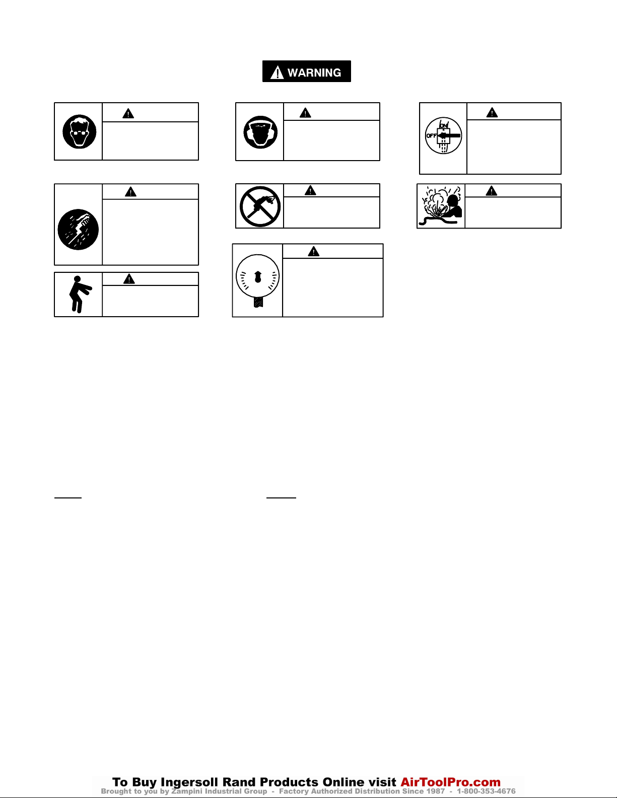
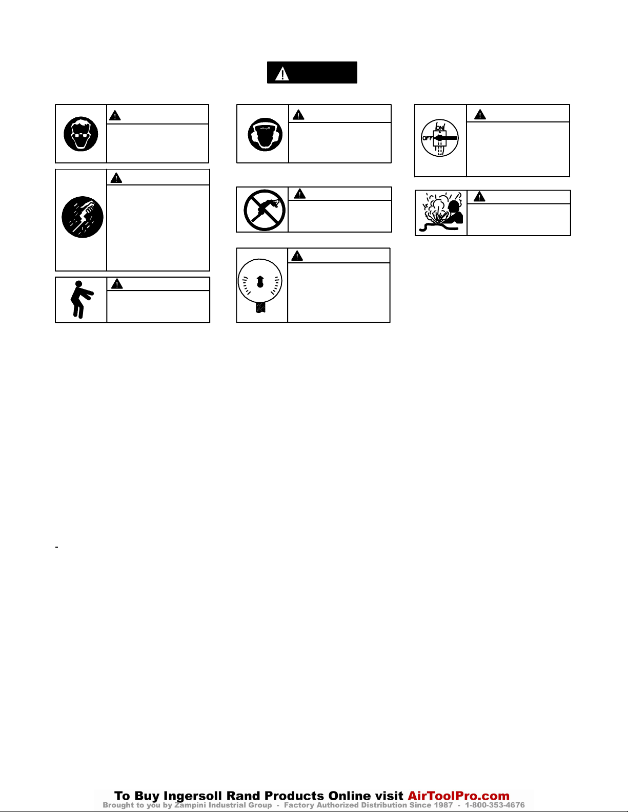
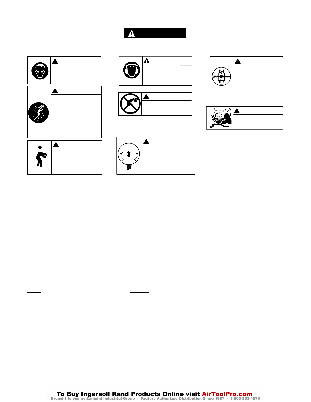
WARNING LABEL IDENTIFICATION
FAILURE TO OBSERVE THE FOLLOWING WARNINGS COULD RESULT IN INJURY.
WARNING
Always wear eye protection
when operating or performing maintenance on this
tool.
WARNING
Air powered tools can vibrate
in use. Vibration, repetitive
motions or uncomfortable positions may be harmful to your
hands and arms. Stop using
any tool if discomfort, tingling
feeling or pain occurs. Seek
medical advice before resuming use.
90 psig
(6.2bar/620kPa)
WARNING
Keep body stance balanced
and firm. Do not overreach
when operating this tool.
SANDER SPECIFIC WARNINGS
• Do not use this tool if actual free speed exceeds the
nameplate rpm.
• Before mounting a sanding belt, after any tool
repair or whenever a Sander is issued for use, check
free speed of the tool with a tachometer to make
certain its actual speed at 90 psig (6.2 bar/620 kPa)
does not exceed rpm stamped or printed on the
nameplate. Sanders in use on the job must be
similarly checked at least once each shift.
• Always use the recommended Ingersoll–Rand
Guard furnished with the Sander.
ADJUSTMENTS
WARNING
Always wear hearing
protection when operating
this tool.
WARNING
Do not carry the tool by
the hose.
WARNING
Operate at 90 psig (6.2 bar/
620 kPa) Maximum air pressure.
• Series CA120 Angle Belt Sanders have a free speed
of 12 000 rpm and a belt speed of 2 700 sfpm while
Series CA200 Angle Belt Sanders have a free speed
of 20 000 rpm and a belt speed of 4 500 sfpm, when
operated at 90 psig (6.2 bar/620 kPa) air pressure.
Operation at higher air pressure will result in
excessive speed.
• Do not operate a Belt Sander with the Cover
removed.
WARNING
Always turn off the air supply and disconnect the air
supply hose before installing, removing or adjusting
any accessory on this tool,
or before performing any
maintenance on this tool.
WARNING
Do not use damaged, frayed
or deteriorated air hoses
and fittings.
INSTALLING A SANDING BELT
When installing a new sanding belt, proceed as follows:
1. For 18” models, slide the Cover rearward toward the
handle of the Sander until it is free. It may require a
light rap on the front edge of the Cover to disengage it
from its locking points.
2. Compress the Idler Wheel and slip the old belt off the
drive Sleeve. Release the pressure on the Idler Wheel
and remove the belt.
3. Position a new belt on the Idler Wheel.
4. Compress the Idler Wheel with the belt and slip the
opposite end of the belt onto the Drive Sleeve around
the Spindle Cap. Release the pressure on the Idler
Wheel.
5. For 18” models, align the Cover with the Guard and
slide it forward toward the Idler Wheel until it snaps
into position and stays there.
6. Operate the Sander at low speed to determine if the
new Belt is tracking properly. If the Belt fails to track
properly, realign the Clevis by tightening or loosening
one or both of the Clevis Mounting Screws.
2
Page 3
PLACING TOOL IN SERVICE
TOOL OPERATION
Sand using any portion of the exposed Sanding Belt. For
best results, sand on that portion of the Belt being pulled by
the Drive Wheel.
LUBRICATION
Ingersoll–Rand No. 10 Ingersoll–Rand No. 67
Ingersoll–Rand No. 50 Ingersoll–Rand No. 68
Ingersoll–Rand No. 63 Ingersoll–Rand No. 77
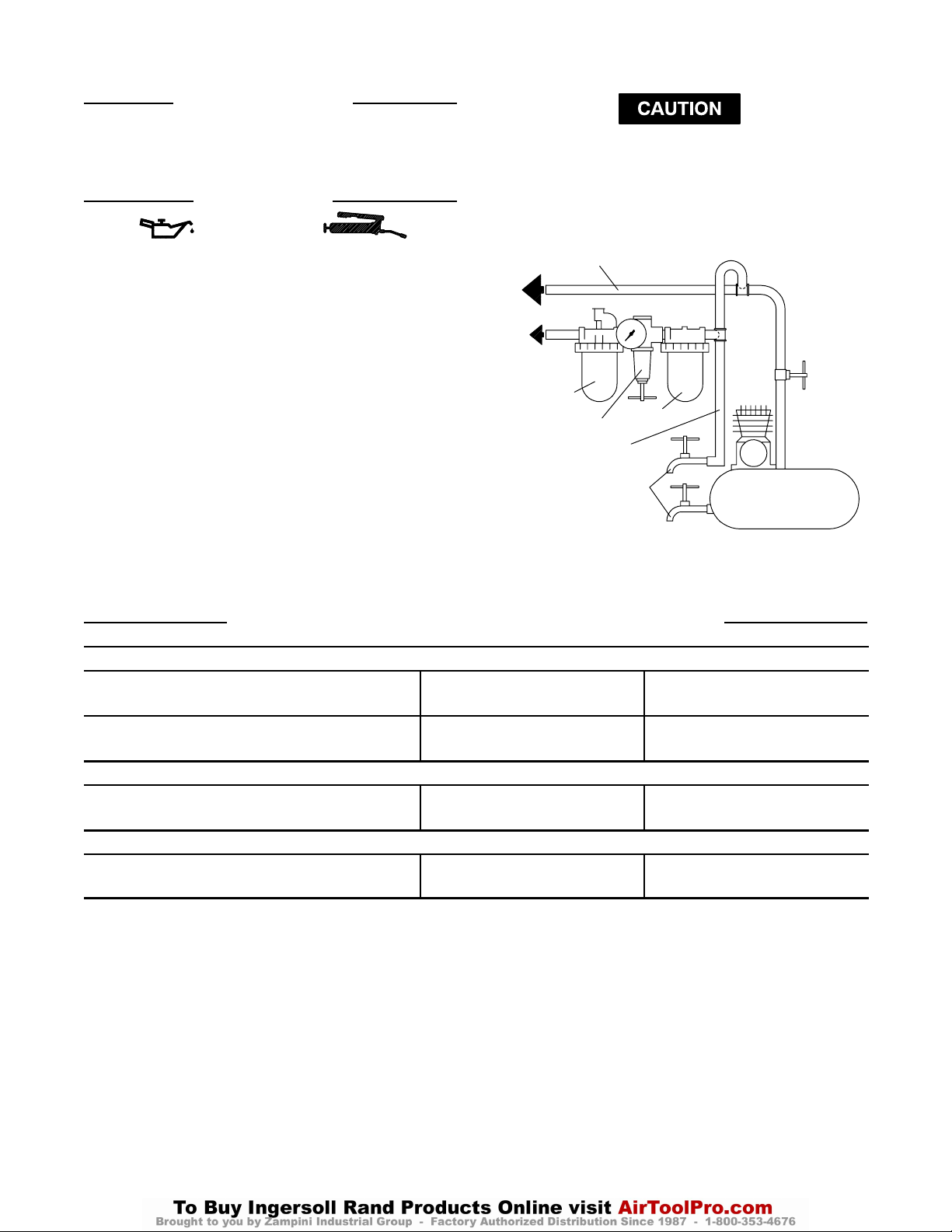
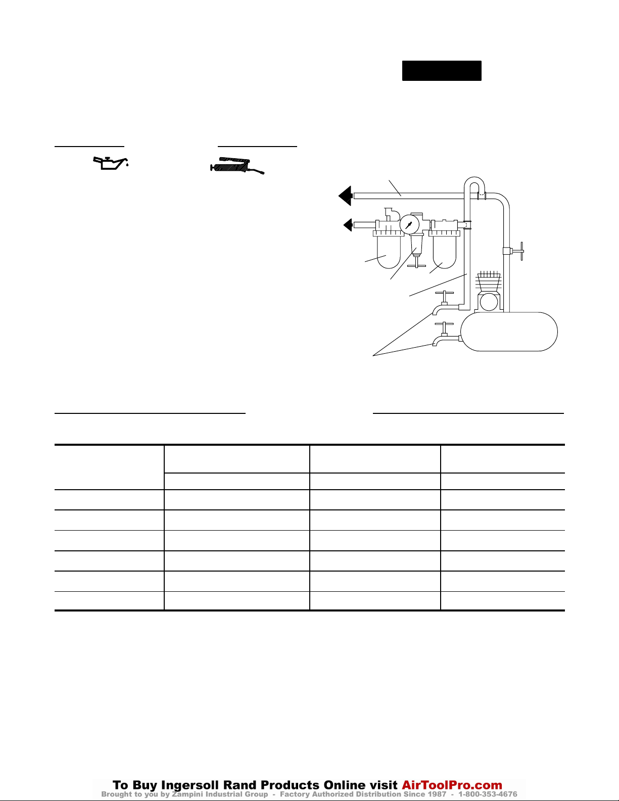
Always use an air line lubricator with these tools.
We recommend the following Filter–Lubricator–Regulator
Unit:
USA – No. C28–04–FKG0–28
After each two hours of operation, if an air line lubricator
is not used, inject 1/2 to 1 cc of Ingersoll–Rand No. 10 Oil
into the Air Inlet.
After each eight hours of operation, inject approximately
1 cc of Ingersoll–Rand No. 67 or Ingersoll–Rand No. 77
Grease into the Angle Head Grease Fitting. Excessive
lubrication will cause grease to work out around the
Arbor.
Do not mark any nonmetallic surface of this tool with
customer identification codes. Such action could affect
tool performance.
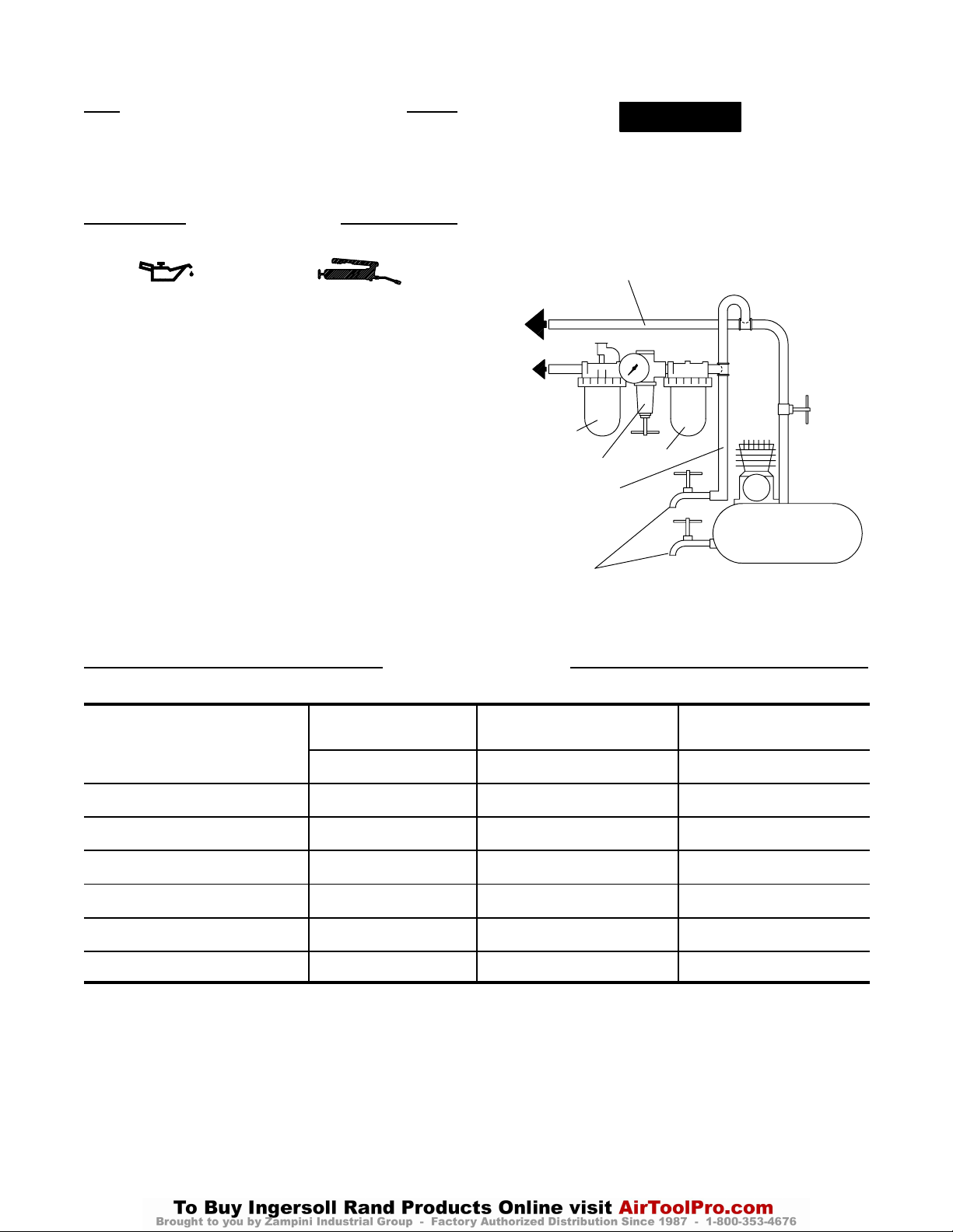
MAIN LINES 3 TIMES
AIR TOOL INLET SIZE
TO
AIR
SYSTEM
TO
AIR
TOOL
LUBRICATOR
REGULATOR
BRANCH LINE 2 TIMES
AIR TOOL INLET SIZE
DRAIN REGULARLY
FILTER
COMPRESSOR
(Dwg. TPD905–1)
HOW TO ORDER SERIES CA ANGLE BELT SANDERS
ANGLE BELT SANDERS WITH 12” x 1/2” BELT
Model Arbor Speed Belt Speed
rpm sfpm
CA200RS812 (Rear Exhaust) 20,000 4,500
CA120RS812 (Rear Exhaust) 12,000 2,700
ANGLE BELT SANDERS WITH 18” x 1/4” BELT
CA200RS418 (Rear Exhaust) 20,000 4,500
CA120RS418 (Rear Exhaust) 12,000 2,700
ANGLE BELT SANDERS WITH 18” x 1/2” BELT
CA200RS818 (Rear Exhaust) 20,000 4,500
CA120RS818 (Rear Exhaust) 12,000 2,700
3
Page 4

Any model listed can be changed to a front exhaust tool by reversing the Flow Ring and aligning the indicator marks
with the letter “F” on the Housing. To order a front exhaust tool from the factory, substitute the letter “F” for the
letter “R” in the model number. Example: CA200RA812 Rear Exhaust Model becomes CA200FS812 Front Exhaust
Model.
HOW TO ORDER CUSTOM MODELS
1. To order a tool with a Locking Lever, select the desired
model and add and “L” to the end of the existing
number. Example: CA200RS812L
Anytime a tool is ordered with a Low–Profile
Concentric Flange, it will come equipped with a
Locking Lever from the factory.
2. To order a tool with a Low–Profile Concentric Flange,
select the desired rear exhaust model and add a “C” to
the end of the existing number. Concentric Flanges are
not available for front exhaust models.
Example: CA200RS812C
4
Page 5

TPD1680
MANUEL D’EXPLOITATION ET D’ENTRETIEN DES
PONCEUSES D’ANGLE À BANDE DE LA SÉRIE CA
NOTE
Les ponçeuses d’ angl e à bande de la Série CA sont desti nées aux applications de tôlerie et de
fonderie. Ces petites ponceuses à bande sont part icul i èrem ent bien adaptées au polissage des
cordons de soudure, du laitier et des joi nt ures de moulage et laissent une très bonne fi ni t ion.
Ingersoll–Rand ne peut être tenu responsable de la modification des outils par le cl ient pour les
adapter à des applications qui n’ont pas été approuvées par Ingersoll–Rand.
ATTENTION
D’IMPORTANTES INFORMATIONS DE SÉCURITÉ SONT JOINTES.
LIRE CE MANUEL AVANT D’UTILISER L’OUTIL.
L’EMPLOYEUR EST TENU DE COMMUNIQUER LES INFORMATIONS
DE CE MANUEL AUX EMPLOYÉS UTILISANT CET OUTIL.
LE NON RESPECT DES AVERTISSEMENTS SUIVANTS PEUT CAUSER DES BLESSURES.
MISE EN SERVICE DE L’OUTIL
Toujours exploiter, inspecter et entretenir cet outil
conformément au Code de sécurité des outils
pneumatiques portatifs de l’American National
Standards Institute (ANSI B186.1).
• Pour la sécurité, les performances optimales et la
durabilité maximale des pièces, cet outil doit être
connecté à une alimentation d’air comprimé de 6,2 bar
(620 kPa) maximum à l’entrée, avec un flexible de
8 mm de diamètre intérieur.
• Couper toujours l’alimentation d’air comprimé et
débrancher le flexible d’alimentation avant d’installer,
déposer ou ajuster tout accessoire sur cet outil, ou
d’entreprendre une opération d’entretien quelconque
sur l’outil.
• Ne pas utiliser des flexibles ou des raccords
endommagés, effilochés ou détériorés.
• S’assurer que tous les flexibles et les raccords sont
correctement dimensionnés et bien serrés. Voir Plan
TPD905–1 pour un exemple type d’agencement des
tuyauteries.
• Utiliser toujours de l’air sec et propre à une pression
maximum de 6,2 bar. La poussière, les fumées
corrosives et/ou une humidité excessive peuvent
endommager le moteur d’un outil pneumatique.
• Ne jamais lubrifier les outils avec des liquides
inflammables ou volatiles tels que le kérosène, le gasol
ou le carburant d’aviation.
• Ne retirer aucune étiquette. Remplacer toute étiquette
endommagée.
UTILISATION DE L’OUTIL
• Porter toujours des lunettes de protection pendant
l’utilisation et l’entretien de cet outil.
• Porter toujours une protection acoustique pendant
l’utilisation de cet outil.
• Tenir les mains, les vêtements flous et les cheveux
longs, éloignés de l’extrémité rotative de l’outil.
• Prévoir, et ne pas oublier, que tout outil motorisé est
susceptible d’à–coups brusques lors de sa mise en
marche et pendant son utilisation.
• Garder une position équilibrée et ferme. Ne pas se
pencher trop en avant pendant l’utilisation de cet outil.
Des couples de réaction élevés peuvent se produire à,
ou en dessous, de la pression d’air recommandée.
• La rotation des accessoires de l’outil peut continuer
pendant un certain temps après le relâchement de la
gâchette.
• Les outils pneumatiques peuvent vibrer pendant
l’exploitation. Les vibrations, les mouvements répétitifs
et les positions inconfortables peuvent causer des
douleurs dans les mains et les bras. N’utiliser plus
d’outils en cas d’inconfort, de picotements ou de
douleurs. Consulter un médecin avant de
recommencer à utiliser l’outil.
• Utiliser les accessoires recommandés par
Ingersoll-Rand.
• A chaque fois que le renvoi d’angle est installé ou
repositionné, le levier de commande doit être
positionné de manière à ce que le couple de réaction
n’ait pas tendance à maintenir le levier de commande
en position “MARCHE”.
• Cet outil n’est pas conçu pour fonctionner dans des
atmosphères explosives.
• Cet outil n’est pas isolé contre les chocs électriques.
F
NOTE
L’utilisation de rechanges autres que les pièces d’origine Ingersoll–Rand peut causer des risques d’insécurité, réduire les
performances de l’outil et augmenter l’entretien, et peut annuler toutes les garanties.
Les réparations ne doivent être effectuées que par des réparateurs qualifiés autorisés. Consultez votre Centre de Service
Ingersoll–Rand le plus proche.
Adressez toutes vos communications au Bureau
Ingersoll–Rand ou distributeur le plus proche.
Ingersoll–Rand Company 1999
Imprimé aux É.U.
Page 6
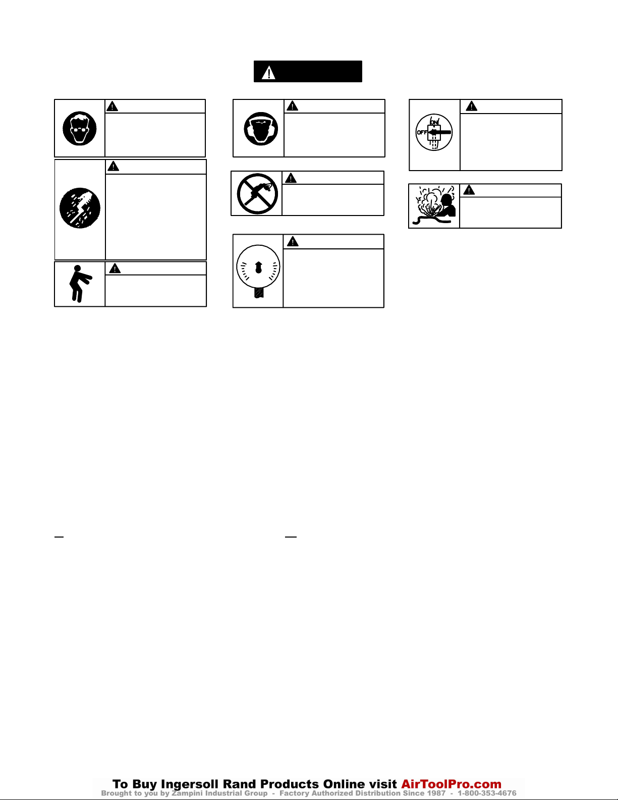
SIGNIFICATION DES ÉTIQUETTES D’AVERTISSEMENT
ATTENTION
LE NON RESPECT DES AVERTISSEMENTS SUIVANTS PEUT CAUSER DES BLESSURES.
ATTENTION ATTENTION
Porter toujours des lunettes
de protection pendant
l’utilisation et l’entretien de
cet outil.
Porter toujours une
protection acoustique
pendant l’utilisation de cet
outil.
ATTENTION
Les outils pneumatiques
peuvent vibrer pendant
l’exploitation. Les vibrations,
les mouvements répétitifs et les
positions inconfortables
peuvent causer des douleurs
dans les mains et les bras.
N’utiliser plus d’outils en cas
d’inconfort, de picotements ou
de douleurs. Consulter un
médecin avant de recommencer
à utiliser l’outil.
ATTENTION
Garder une position équilibrée et
ferme. Ne pas se pencher trop
en avant pendant
l’utilisation de cet outil.
90 psig
(6.2bar/620kPa)
Ne pas transporter l’outil
par son flexible.
Utiliser de l’air comprimé
à une pression maximum
de 6,2 bar (620 kPa).
ATTENTION
ATTENTION
ATTENTION
Couper toujours l’alimentation
d’air comprimé et débrancher le
flexible d’alimentation avant
d’installer, déposer ou ajuster
tout accessoire sur cet outil, ou
d’entreprendre une opération
d’entretien quelconque sur l’outil.
ATTENTION
Ne pas utiliser des flexibles ou
des raccords endommagés,
effilochés ou détériorés.
AVERTISSEMENTS SPÉCIFIQUES AUX PONCEUSES
• Ne pas utiliser cet outil si la vitesse à vide réelle
dépasse celle indiquée sur la plaque signalétique.
• Avant de monter une bande de ponçage, après toute
réparation de l’outil ou chaque fois que la ponceuse
est sortie du magasin, vérifier la vitesse à vide de
l’outil avec un compte–tours pour s’assurer qu’à
une pression d’alimentation de 6,2 bar (620 kPa),
elle ne dépasse pas celle poinçonnée ou imprimée
sur la plaque signalétique. Les ponceuses sorties sur
chantier doivent être vérifiées de la même façon au
moins une fois par poste.
• Utiliser toujours la ponceuse équipée du carter de
RÉGLAGES
MONTAGE DE LA BANDE ABRASIVE
Pour installer une nouvelle bande abrasive, procécer
comme suit :
1. Pour les modèles de 18’’, glisser le couvercle vers
l’arrière en direction de la poignée, jusqu’à ce qu’il soit
libre. Un léger coup sur le devant du couvercle pourra
être nécessaire pour le désengager de ses points de
verrouillage.
2. Comprimer la roue libre et faire glisser l’ancienne
bande du manchon d’entraînement. Relâcher la
pression sur la roue libre et déposer la bande.
protection recommandé par Ingersoll–Rand.
• Les ponceuses d’angle à bande de la série CA120
ont une vitesse à vide de 12 000 tr/mn et une vitesse
de bande de 2 700 sfpm, tandis que les ponceuses
d’angle à bande de la série CA200 ont une vitesse à
vide de 20 000 tr/mn et une vitesse de bande de
4 500 sfpm, lorsqu’alimentées à une pression d’air
de 6,2 bar/620 kPa. L’exploitation à une pression
d’air supérieure produira une vitesse excessive.
• Ne jamais exploiter la ponceuse lorsque le couvercle
est déposé.
3. Placer une bande neuve sur la roue libre.
4. Comprimer la roue libre et la bande et faire glisser
l’extrémité opposée de la bande sur le manchon
d’entraînement autour du chapeau de broche. Relâcher
la pression sur la roue libre.
5. Pour les modèles de 18’’, aligner le couvercle et le
carter de protection et glisser le couvercle vers la roue
libre jusqu’à ce qu’il s’engage en position.
6. Faire tourner la ponceuse à basse vitesse pour vérifier
l’alignement correct de la bande. Si la bande n’est pas
alignée, ajuster la chape en serrant ou en desserrant une
ou les deux vis de montage de chape.
6
Page 7
MISE EN SERVICE DE L’OUTIL
EXPLOITATION DE L’OUTIL
Poncer en utilisant n’importe quelle section exposée de la
bande de ponçage. Pour obtenir les meilleurs résultats,
utiliser la partie de la bande tractée par la roue
d’entraînement.
LUBRIFICATION
Ingersoll–Rand No. 10 Ingersoll–Rand No. 67
Ingersoll–Rand No. 50 Ingersoll–Rand No. 68
Ingersoll–Rand No. 63 Ingersoll–Rand No. 77
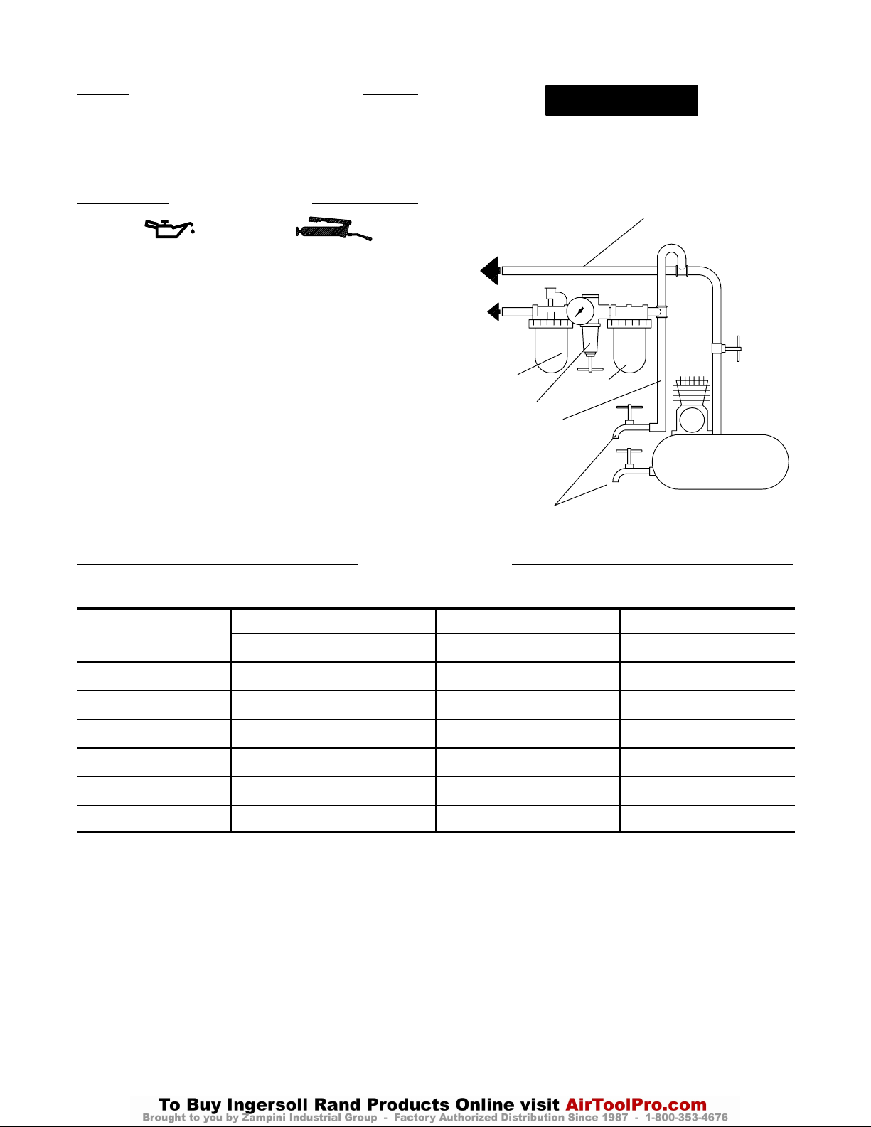
Utiliser toujours un lubrificateur avec ces outils. Nous
recommandons l’emploi du filtre–régulateur–lubrificateur
suivant :
USA – No. C28–04–FKG0–28
Toutes les deux heures de fonctionnement, si un
lubrificateur de ligne n’est pas utilisé, injecter 1/2 à 1 cm
d’huile Ingersoll–Rand No. 10 dans le raccord d’admission.
Toutes les huit heures de fonctionnement, injecter 1 cm
de graisse Ingersoll–Rand No. 67 ou No. 77 dans le raccord
de graissage du renvoi d’angle. Tout graissage excessif
causera l’extrusion de la graisse autour de l’arbre.
3
3
AVERTISSEMENT
Ne pas marquer les codes d’identification client sur les
surfaces non métalliques de cet outil. De telles actions
pourraient affecter les performances de l’outil.
TUYAUTERIE PRINCIPALE
AU MOINS 3 FOIS LA DIMEN-
VERS LE
RÉSEAU D’AIR
COMPRIMÉ
VERS
L’OUTIL
PNEU-
MATIQUE
LUBRIFICATEUR
RÉGULATEUR
LIGNE SECONDAIRE AU
MOINS 2 FOIS LA DIMEN-
SION DE L’ADMISSION
D’AIR DE L’OUTIL
VIDANGER
RÉGULIÈREMENT
SION DE L’ADMISSION D’AIR
DE L’OUTIL
FILTRE
COMPRESSEUR
(Plan TPD905–1)
SPÉCIFICATIONS
Modèle Dimension de la Bande Vitesse d’arbre Vitesse de la bande
pouces (mm) tr/mn sfpm
CA120RS812ML 12 x 1/2 (305 x 13) 12.000 2.700
CA120RS418ML 18 x 1/4 (457 x 6) 12.000 2.700
CA120RS818ML 18 x 12 (457 x 13) 12.000 2.700
CA200RS812ML 12 x 1/2 (305 x 13) 20.000 4.500
CA200RS418ML 18 x 1/4 (457 x 6) 20.000 4.500
CA200RS818ML 18 x 12 (457 x 13) 20.000 4.500
7
Page 8
E
TPD1680
MANUAL DE USO Y MANTENIMIENTO PARA
LIJADORAS DE CORREA ANGULARES DE LA SERIE CA
NOTA
Las lijadoras de correa de la serie CA están diseñadas para trabajos en la industria de fabricación de
productos metálicos y en apl i caci ones de fundición. Estas pequeñas li j adoras de correa angulares
resultan muy eficaces para am ol ar cordones de soldadura, líneas de rebabas y escori a, obteniendo
un acabado fi no.
Ingersoll–Rand no aceptará responsabilidad alguna por la modificación de las herramientas
efectuada por el cliente para las apli caci ones que no hayan sido consultadas con Ingersoll–Rand.
AVISO
SE ADJUNTA INFORMACIÓN IMPORTANTE DE SEGURIDAD.
LEA ESTE MANUAL ANTES DE UTILIZAR LA HERRAMIENTA.
ES RESPONSABILIDAD DE LA EMPRESA ASEGURARSE DE QUE
EL OPERARIO ESTÉ AL TANTO DE LA INFORMACIÓN QUE CONTIENE ESTE MANUAL.
EL HACER CASO OMISO DE LOS AVISOS SIGUIENTES PODRÍA OCASIONAR LESIONES.
PARA PONER LA HERRAMIENTA EN SERVICIO
Utilice, examine y mantenga siempre esta
herramienta conforme al código de seguridad para
herramientas neumáticas portátiles de la American
National Standards Institute (ANSI B186.1).
• Para mayor seguridad, rendimiento óptimo y larga
vida útil de las piezas, utilice esta herramienta a una
presión de aire máxima de 90 psig
(6,2 bar/620 kPa) con una manguera de suministro de
aire con diámetro interno de 8 mm.
• Corte siempre el suministro de aire y desconecte la
manguera de suministro de aire antes de instalar,
desmontar o ajustar cualquier accesorio de esta
herramienta, o antes de realizar cualquier operación
de mantenimiento de la misma.
• No utilice mangueras de aire y racores da ñados,
desgastados o deteriorados.
• Asegúrese de que todos los racores y mangueras sean
del tamaño correcto y estén bien apretados. El Esq.
TPD905–1 muestra una disposición característica de
las tuberías.
• Use siempre aire limpio y seco a una presión máxima
de 90 psig (6,2 bar/620 kPa). El polvo, los gases
corrosivos y el exceso de humedad pueden estropear el
motor de una herramienta neumática.
• No lubrique las herramientas con líquidos inflamables
o volátiles tales como queroseno, gasoil o combustible
para motores a reacción.
• No saque ninguna etiqueta. Sustituya toda etiqueta
dañada.
UTILIZACIÓN DE LA HERRAMIENTA
• Lleve siempre protección ocular cuando utilice esta
NOTA
herramienta o realice operaciones de mantenimiento
en la misma.
• Lleve siempre protección para los oídos cuando utilice
esta herramienta.
• Mantenga las manos, la ropa suelta y el cabello largo
alejados del extremo giratorio de la herramienta.
• Anticipe y esté atento a los cambios repentinos en el
movimiento durante la puesta en marcha y utilización
de toda herramienta motorizada.
• Mantenga una postura del cuerpo equilibrada y firme.
No estire demasiado los brazos al manejar la
herramienta. Pueden darse elevados pares de reacción
a la presión de aire recomendada, e incluso a presiones
inferiores.
• Los accesorios de la herramienta podrían seguir
girando brevemente después de haberse soltado la
palanca de mando.
• Las herramientas neumáticas pueden vibrar durante el
uso. La vibración, los movimientos repetitivos o las
posiciones incómodas pueden dañarle los brazos y
manos. En caso de incomodidad, sensación de
hormigueo o dolor, deje de usar la herramienta.
Consulte con el médico antes de volver a utilizarla.
• Utilice únicamente los accesorios Ingersoll–Rand
recomendados.
• Cuando se instale o reposicione la cabeza angular, la
palanca de mando deberá colocarse de forma que la
reacción de par no tienda a retener el mando en la
posición de “ON” (ACCIONAMIENTO).
• Esta herramienta no ha sido diseñada para trabajar en
ambientes explosivos.
• Esta herramienta no está aislada contra descargas
eléctricas.
El uso de piezas de recambio que no sean las auténticas piezas Ingersoll–Rand puede poner en peligro la seguridad, reducir el
rendimiento de la herramienta y aumentar los cuidados de mantenimiento necesarios, así como invalidar toda garantía.
Las reparaciones sólo se deben encomendar a personal debidamente cualificado y autorizado. Consulte con el centro de servicio
autorizado Ingersoll–Rand más próximo.
Toda comunicación se deberá dirigir a la oficina o
al distribuidor Ingersoll–Rand más próximo.
Ingersoll–Rand Company 1999
Impreso en EE. UU.
Page 9
ETIQUETAS DE AVISO
AVISO
EL HACER CASO OMISO DE LOS AVISOS SIGUIENTES PODRÍA OCASIONAR LESIONES.
ADVERTENCIA
Usar siempre protección ocular
al manejar o realizar operaciones de mantenimiento en
esta herramienta.
ADVERTENCIA
Las herramientas neumáticas
pueden vibrar durante el uso.
La vibración, los movimientos
repetitivos o las posiciones
incómodas podrían dañarle los
brazos y las manos. En caso
de incomodidad, sensación de
hormigueo o dolor, dejar de
usar la herramienta. Consultar
al médico antes de volver a utilizarla.
90 psig
(6.2bar/620kPa)
ADVERTENCIA
Mantener una postura del cuerpo
equilibrada y firme. No estirar demasiado los brazos al manejar la
herramienta.
AVISOS ESPECÍFICOS SOBRE LAS LIJADORAS
• No use esta herramienta si la velocidad en vacío real
excede la indicada en la placa de identificación.
• Antes de montar una correa de lijado, después
cualquier reparación de la herramienta o al poner
en servicio una lijadora, compruebe con un
tacómetro la velocidad en vacío de la herramienta
para asegurarse de que su velocidad real a 90 psig
(6.2 bar/620 kPa) no exceda la velocidad estampada
o impresa en la placa de identificación. Las
lijadoras que están en uso también se deberán
revisar al menos una vez en cada turno de trabajo.
• Use siempre el protector recomendado por
Ingersoll–Rand y suministrado con la lijadora.
ADVERTENCIA
Usar siempre protección
para los oídos al manejar
esta herramienta.
ADVERTENCIA
No coger la herramienta
por la manguera para levantarla.
ADVERTENCIA
Manejar la herramienta a una
presión de aire máxima de 90
psig (6,2 bar/620 kPa).
• Las lijadoras de correa de la serie CA120 tienen
una velocidad en vacío de 12000 rpm y una
velocidad periférica de correa de 2700 pies/min.,
mientras que las lijadoras de correa angulares de la
serie CA200 tienen una velocidad en vacío de 20000
rpm y una velocidad periférica de correa de 4500
pies/min., cuando se operan a una presión de aire de
90 psig (6.2 bar/620 kPa). Su utilización a una
presión superior producirá un exceso de velocidad.
• No utilice la lijadora de correa sin la cubierta.
ADVERTENCIA
Cortar siempre el suministro
de aire y desconectar la manguera de suministro de aire
antes de instalar, retirar o ajustar cualquier accesorio de esta
herramienta, o antes de realizar
cualquier operación de mantenimiento de la misma.
ADVERTENCIA
No utilizar mangueras de aire
y accesorios dañados, desgastados ni deteriorados.
AJUSTES
INSTALACIÓN DE UNA CORREA DE LIJADO
Para instalar una correa de lijado nueva, proceda como sigue:
1. Para modelos de 18 pulg., deslice la cubierta hacia atrás,
hacia la empuñadura de la lijadora, hasta que quede suelta.
Puede que sea necesario golpear ligeramente el extremo
delantero de la cubierta para soltarla de los puntos de
cierre.
2. Comprima la rueda intermedia y deslice la correa antigua
fuera del manguito de accionamiento. Libere la presión de
la rueda intermedia y saque la correa.
3. Coloque una correa nueva en la rueda intermedia.
4. Comprima la rueda intermedia con la correa y deslice el
extremo opuesto de dicha correa sobre el manguito de
accionamiento, alrededor de la tapa del husillo. Libere la
presión sobre la rueda intermedia.
5. Para modelos de 18 pulg., alinee la cubierta con el
protector y deslícela hacia delante, hacia la rueda
intermedia, hasta que salte a su posició n y se quede allí.
6. Utilice la lijadora a baja velocidad para ver si la correa
nueva funciona con normalidad. Si la correa no funciona
debidamente, vuelva a alinear la horquilla ap retando o
aflojando para ello uno de los tornillos de montaje de la
horquilla o ambos.
9
Page 10
PARA PONER LA HERRAMIENTA EN SERVICIO
FUNCIONAMIENTO DE LA HERRAMIENTA
Proceda al lijado utilizando para ello cualquier parte de la
correa de lijado que quede expuesta. Para obtener unos
resultados óptimos, lije utilizando la parte de la correa de la
que tira la muela de accionamiento.
LUBRICACIÓN
Ingersoll–Rand Nº 10 Ingersoll–Rand Nº 67
Ingersoll–Rand Nº 50 Ingersoll–Rand Nº 68
Ingersoll–Rand Nº 63 Ingersoll–Rand Nº 77
Utilice siempre un lubricador de aire comprimido con estas
herramientas. Recomendamos utilizar el siguiente conjunto
de filtro–lubricador–regulador:
USA – Nº C28–04–FKG0–28
Después de cada dos horas de funcionamiento, si no se
usa un lubricador de línea de aire comprimido, inyecte
1/2 – 1 cc de aceite Ingersoll–Rand Nº 10 en la admisión de
aire.
Después de cada ocho horas de uso, inyecte
aproximadamente 1 cc de grasa Ingersoll–Rand Nº 67 o 77
en el engrasador situado en la cabeza angular. Un exceso de
lubricación causará que caiga grasa en el eje.
PRECAUCIÓN
No marque ninguna superficie no metálica de esta
herramienta con los códigos de identificación de cliente.
Tal acción podría afectar al rendimiento de la
herramienta.
TUBERÍAS PRINCIPALES 3
VECES EL TAMAÑO DE
ENTRADA DE HERRAMIENTA
AL SISTEMA
NEUMÁTICO
A LA
HERRA–
MIENTA
NEUMÁTICA
LUBRICADOR
TUBERÍA DE RAMAL
2 VECES EL TAMAÑO
DE ENTRADA DE
HERRAMIENTA
NEUMÁTICA
PURGAR
PERIÓDICAMENTE
NEUMÁTICA
REGULADOR
FILTRO
COMPRESOR
(Esq. TPD905–1)
ESPECIFICACIONES
Modelo Tamaño
de la correa
pulg. (mm) rpm pies/min.
CA120RS812ML 12 x 1/2 (305 x 13) 20.000 4.500
CA120RS418ML 12 x 1/2 (305 x 13) 12.000 2.700
CA120RS818ML 18 x 1/4 (457 x 6) 20.000 4.500
CA200RS812ML 18 x 1/4 (457 x 6) 12.000 2.700
CA200RS418ML 18 x 12 (457 x 13) 20.000 4.500
CA200RS818ML 18 x 12 (457 x 13) 12.000 2.700
Velocidad del eje Velocidad periférica de la
correa
10
Page 11

P
TPD1680
MANUAL DE FUNCIONAMENTO E MANUTENÇÃO PARA
LIXADORES COM CORREIA EM ÂNGULO SÉRIES CA
AVISO
Os Lixadores com Correia em Ângulo Séries CA são concebidos para aplicações de trabalho em
indústria e fundição de metais. Estes pequenos Lixadores são muito eficientes em esmerilar cordões
de solda, e linhas de separação e madei ra, deixando um fino acabamento.
A Ingersoll–Rand não é responsável por modificações, feitas pelo cliente em ferramentas, nas quais
a Ingersoll–Rand não tenha sido consultada.
ADVERTÊNCIA
INFORMAÇÃO DE SEGURANÇA IMPORTANTE EM ANEXO.
LEIA ESTE MANUAL ANTES DE OPERAR A FERRAMENTA.
É DA RESPONSABILIDADE DO EMPREGADOR COLOCAR A INFORMAÇÃO
DESTE MANUAL NAS MÃOS DO OPERADOR.
O NÃO CUMPRIMENTO DAS SEGUINTES ADVERTÊNCIAS PODE RESULTAR EM FERIMENTOS.
COLOCANDO A FERRAMENTA EM
FUNCIONAMENTO
Sempre opere, inspeccione e mantenha esta
ferramenta de acordo com o Código de Segurança
do Instituto Americano de Padrões Nacionais para
Ferramentas Pneumáticas Portáteis (ANSI B186.1).
• Para segurança, máximo desempenho e máxima
durabilidade das peças, opere esta ferramenta com
uma pressão de ar máxima de 6,2 bar/620 kPa
(90 psig) na entrada da mangueira de alimentação de
ar com diâmetro interno de 8 mm (5/16”).
• Desligue sempre a alimentação de ar e desconecte a
mangueira de alimentação de ar antes de instalar,
remover ou ajustar qualquer acessório nesta
ferramenta, ou antes de executar qualquer serviço de
manutenção nesta ferramenta.
• Não use mangueiras de ar ou adaptadores danificados,
gastos ou deteriorados.
• Certifique–se de que todas as mangueiras e
adaptadores sejam do tamanho correcto e estejam
apertados com firmeza. Veja o Desenho TPD905–1
para um arranjo típico de tubagem.
• Use sempre ar seco e limpo com pressão máxima de
90 psig. Pó, fumos corrosivos e/ou humidade
excessiva podem arruinar o motor de uma
ferramenta pneumática.
• Não lubrifique as ferramentas com líquidos
inflamáveis ou voláteis tais como querosene, diesel
ou combustível de jactos.
• Não remova nenhum rótulo. Reponha qualquer
rótulo danificado.
USANDO A FERRAMENTA
• Use sempre óculos de protecção quando estiver
operando ou executando serviço de manutenção nesta
ferramenta.
• Use sempre protecção contra ruído ao operar esta
ferramenta.
• Mantenha as mãos, partes do vestuário soltas e cabelos
compridos afastados da extremidade em rotação.
• Antecipe e esteja alerta a mudanças repentinas no
movimento quando ligar e operar qualquer
ferramenta motorizada.
• Mantenha a posição do co rpo equilibrada e firme. Não
exagere quando operar esta ferramenta. Torques de
reacção elevados podem ocorrer na ou abaixo da
pressão de ar recomendada.
• Os acessórios da ferramenta podem continuar a
impactar brevemente após a pressão ter sido aliviada.
• Ferramentas accionadas pneumáticamente podem
vibrar em uso. Vibração, movimentos repetitivos ou
posições desconfortáveis podem ser prejudiciais às
mãos e aos braços. Pare de usar a ferramenta caso
ocorra algum desconforto, sensação de formigueiro
ou dor. Procure assistência médica antes de
retornar ao trabalho.
• Use acessórios recomendados pela Ingersoll–Rand.
• Quando quer que o Cabeçote em Ångulo seja
instalado ou reposto, a Válvula Reguladora de
Presão deve ser posicionada de modo que um
torque de reacção não tenderá a reter o curso na
posição “LIGADA”.
• Esta Ferramenta não foi concebida para trabalhos
em atmosferas explosivas.
• Esta Ferramenta não está isolada contra choques
eléctricos.
AVISO
O uso de peças de substituição que não sejam genuinamente da Ingersoll–Rand podem resultar em riscos de segurança,
diminuição do desempenho da ferramenta, aumento da necessidade de manutenção e pode invalidar todas as garantias.
As reparações devem ser feitas somente p or p essoal tr einado autorizado. C onsulte o C entr o de S erviços d a I ngersoll–Rand
mais próximo.
Envie Todos os Comunicados Para o Distribuidor
ou Escritório da Ingersoll–Rand Mais Próximo.
Ingersoll–Rand Company 1999
Impresso nos E.U.A.
Page 12
IDENTIFICAÇÃO DO RÓTULO DE ADVERTÊNCIA
ADVERTÊNCIA
O NÃO CUMPRIMENTO DAS SEGUINTES ADVERTÊNCIAS PODE RESULTAR EM FERIMENTOS.
ADVERTÊNCIA
Use sempre óculos de
protecção quando estiver
operando ou executando algum
serviço de manutenção nesta
ferramenta.
ADVERTÊNCIA
Ferramentas accionadas
pneumáticamente podem vibrar
em uso. Vibração, movimentos
repetitivos ou posições
desconfortáveis podem ser
prejudiciais às mãos e aos
braços. Pare de usar a
ferramenta caso ocorra algum
desconforto, sensação de
formigueiro ou dor. Procure
assistência médica antes de
retornar ao trabalho.
ADVERTÊNCIA
Mantenha a posição do corpo
equilibrada e firme. Não
exagere quando operar esta
ferramenta. Torques de reacção
elevados podem ocorrer sob a
pressão de ar recomendada.
90 psig
(6.2bar/620kPa)
ADVERTÊNCIAS ESPECÍFICAS SOBRE O LIXADOR
• Não use esta ferramenta se a velocidade livre total
exceder a rpm indicada na placa de identificação.
• Antes de montar a correia de lixamento, depois de
qualquer reparação de ferramenta ou quando se
pretende que um Lixador seja colocado em
funcionamento, verifique a velocidade livre do Lixador
com um tacómetro para se certificar de que a sua
velocidade real a 6,2 bar/620kPa (90 psig) não exceda
a rpm selada ou impressa na placa de identificação. Os
Lixadores em funcionamento devem ser similarmente
verificados pelo menos uma vez em cada turno.
ADVERTÊNCIA
Use sempre protecção contra o
ruído ao operar esta ferramenta.
ADVERTÊNCIA
Não carregue a ferramenta
segurando na mangueira.
ADVERTÊNCIA
Opere com pressão do ar Máxima
de 90 psig (6,2–6,9 bar).
• Use sempre o Protector do Disco da Ingersoll–Rand
fornecido com o Lixador.
• Os Lixadores em Ângulo Séries CA120 têm uma
velocidade livre de 12 000 rpm e uma velocidade de
correia de 2 700 sfpm enquanto os das Séries CA200
têm velocidade livre de 20 000 rpm e uma
velocidade da correia de 4500 sfpm, quando
operados sob uma pressão de ar igual a
6,2 bar/620 kPa (90 psig). Operação sob pressões de
ar mais elevadas resultará em velocidade excessiva.
• Nao opere o lixador com correia com a capa removida.
ADVERTÊNCIA
Desligue sempre a alimentação
de ar e desconecte a mangueira
de alimentação de ar antes de
instalar, remover ou ajustar
qualquer acessório nesta
ferramenta, ou antes de
executar algum serviço de
manutenção nesta ferramenta.
ADVERTÊNCIA
Não use mangueiras de ar ou
adaptadores danificados,
gastos ou deteriorados.
AJUSTES
INSTALANDO UMA CORREIA
DE LIXAMENTO
Quando uma correia de lixamento nova for instalada
proceda da seguinte maneira:
1. Para modelos com 18”, deslize a Capa para trás em
direção ao punho do Lixador até libertá–la. Pode ser
necessário uma leve pancada na extremidade frontal da
capa para livrá–lo dos seus pontos de travamento.
2. Comprima o Disco Falso e retire a correia velha para
fora da Camisa de comando. Alivie a pressão no Disco
Falso e remova a correia.
3. Posicione a correia nova no Disco Falso.
4. Comprima o Disco Falso com a correia e coloque a
extremidade oposta da correia na Camisa de Comando ao
redor do Tampo do Fuso. Alivie a pressão no Disco Falso.
5. Para modelos com 18”, alinhe a Capa com o Protector
e deslize para frente em direção do Disco Falso até que
ele prenda na posição e lá permaneça.
6. Opere o Lixador com velocidade baixa para verificar
se a nova Correia está propriamente colocada. Se a
Correia não correr no trilho de maneira apropriada,
realinhe o Olhal ao apertar ou afrouxar um ou ambos
Parafusos de Montagem do Olhal.
12
Page 13
COLOCANDO A FERRAMENTA EM FUNCIONAMENTO
OPERAÇÃO DA FERRAMENTA
Lixe usando qualquer porção da Correia de Lixamento
exposta. Para resultados melhores, lixe naquela porção da
Correia sendo puxada pelo Disco de Comando.
LUBRIFICAÇÃO
Ingersoll–Rand No. 10 Ingersoll–Rand No. 67
Ingersoll–Rand No. 50 Ingersoll–Rand No. 68
Ingersoll–Rand No. 63 Ingersoll–Rand No. 77
Use sempre um lubrificador de ar de linha com estas
ferramentas. Nós recomendamos a seguinte Unidade
Filtro–Lubrificador–Regulador:
USA – No. C28–04–FKG0–28
Depois de cada duas horas de operação, se um
lubrificador de ar de linha não estiver sendo usado, injecte de
1/2 a 1 cc de Óleo Ingersoll–Rand No. 10 na Entrada de Ar.
Depois de cada oito horas de operação, injecte cerca de 1
cc de Massa Ingersoll–Rand No 67 ou Ingersoll–Rand No
77 no Adaptador de Massa do Cabeçote em Ângulo.
Lubrificação excessiva poderá fazer com que a graxa
de espalhe em volta da Árvore de Montagem.
CUIDADO
Não marque as superfícies não metálicas desta
ferramenta com códigos de identificação do cliente. Tais
acções podem afectar o desempenho da ferramenta.
LINHAS PRINCIPAIS 3 VEZES O TAMANHO DA
PARA
SISTEMA DE AR
PARA
FERRAMENTA
PNEUMÁTICA
LUBRIFICADOR
LINHA RAMIFICADA
2 VEZES O TAMANHO
DA ENTRADA DA
FERRAMENTA
PNEUMÁTICA
ENTRADA DA FERRAMENTA PNEUMÁTICA
REGULADOR
DRENE
REGULARMENTE
FILTRO
(Desenho TPD905–1)
COMPRESSOR
ESPECIFICAÇÕES
Modelo Tamanho
da Correia
mm (pol.) rpm sfpm
CA120RS812ML 305 x 13 (12 x 1/2) 12.000 2.700
CA120RS418ML 305 x 13 (12 x 1/2) 12.000 2.700
CA120RS818ML 457 x 6 (18 x 1/4) 12.000 2.700
CA200RS812ML 457 x 6 (18 x 1/4) 20.000 4.500
CA200RS418ML 457 x 13 (18 x 1/2) 20.000 4.500
CA200RS818ML 457 x 13 (18 x 1/2) 20.000 4.500
Velocidade da Árvore Velocidada da Correia
13
Page 14
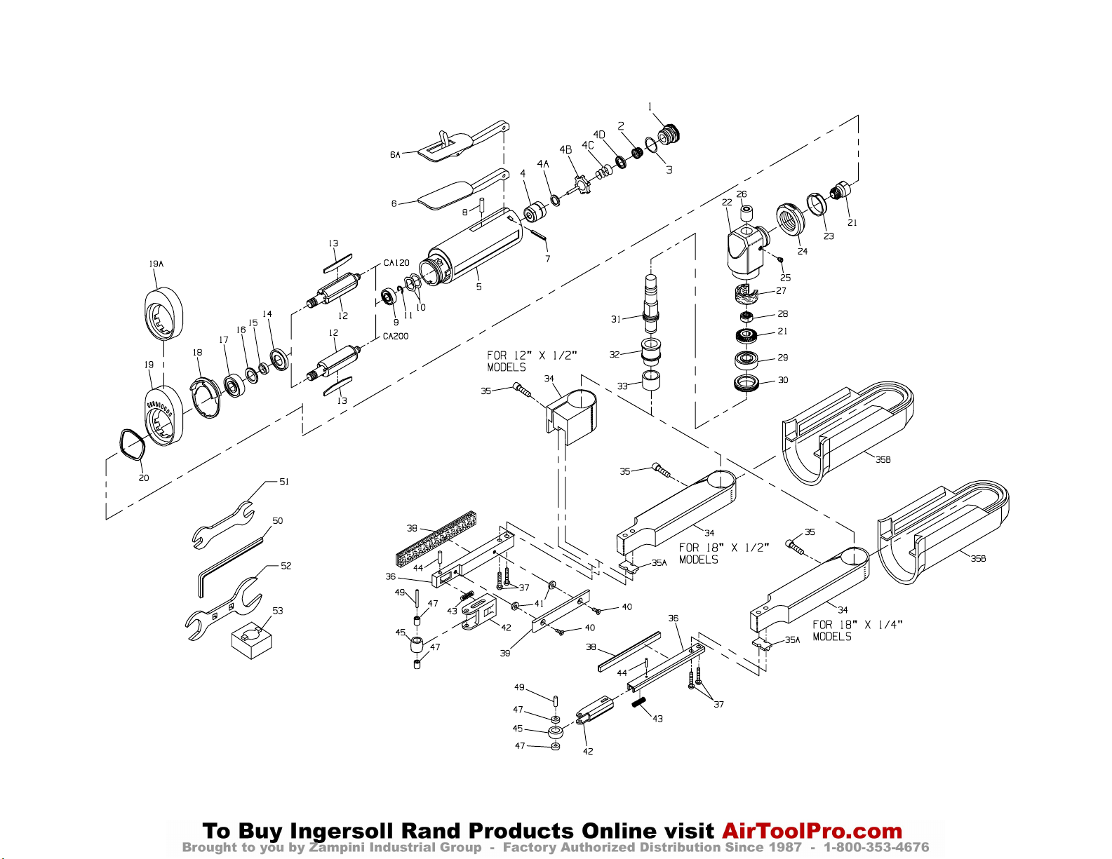
14
MAINTENANCE SECTION
(Dwg. TPA1302–3)
Page 15
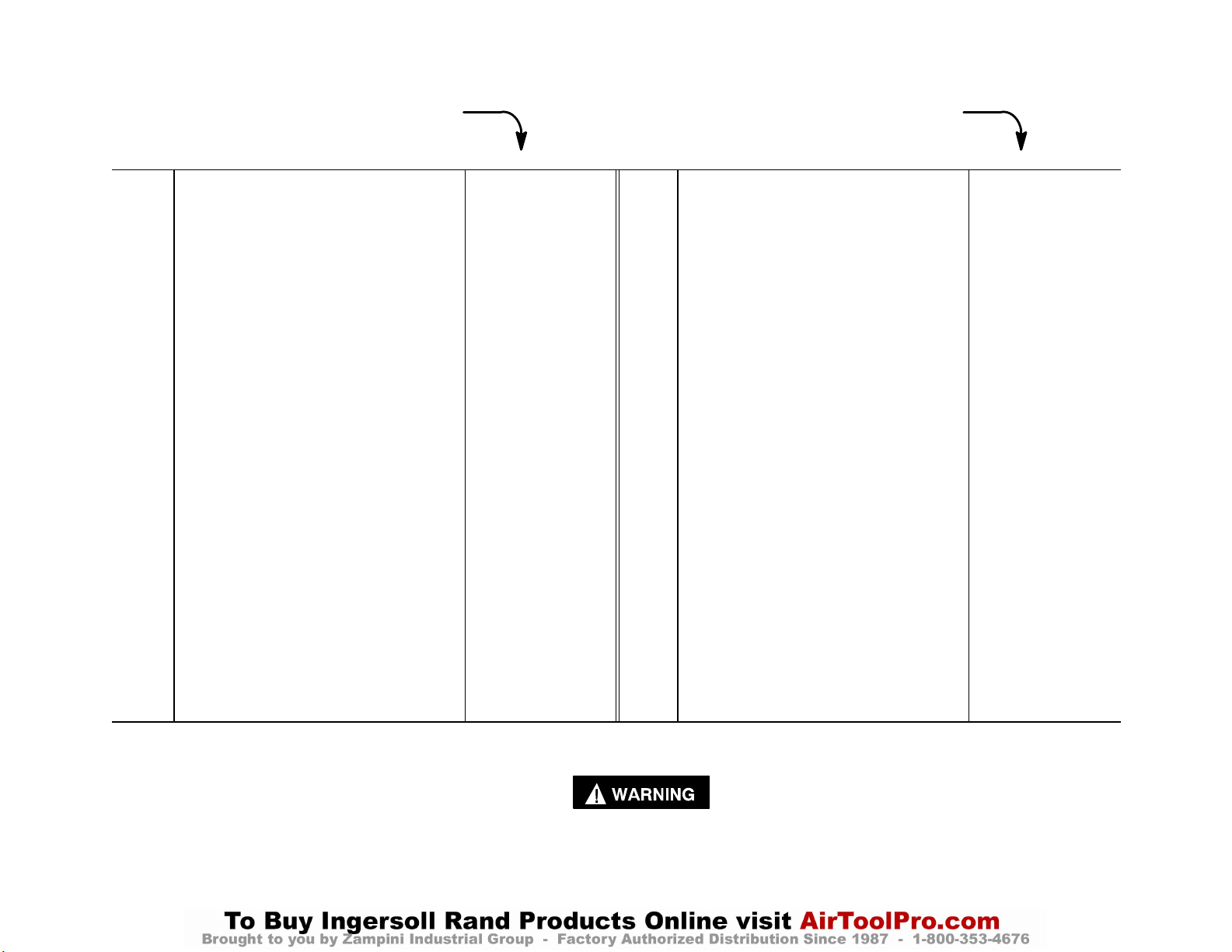
15
PART NUMBER FOR ORDERING PART NUMBER FOR ORDERING
1 Inlet Assembly . . . . . . . . . . . . . . . . . . . . . . . LG1–A465A 17 Front Rotor Bearing . . . . . . . . . . . . . . . . . . . LG1–24
2 Inlet Screen . . . . . . . . . . . . . . . . . . . . . . R1602–61 18 Flow Ring
• 3 Inlet Seal . . . . . . . . . . . . . . . . . . . . . . . . 85H–167 for CA120 (brown) . . . . . . . . . . LG1–103–1
Throttle Valve Kit . . . . . . . . . . . . . . . . . . . . LG1–K300 for CA200 (red) . . . . . . . . . . . . . LG1–103–3
4 Throttle Valve Cartridge Case . . . . . . . . LG1–300A 19 High Profile Flange . . . . . . . . . . . . . . . . . . . LG1–23
4A Throttle Valve Seat . . . . . . . . . . . . . . . . LG1–303 # 19A Low Profile Concentric Flange
4B Throttle Valve . . . . . . . . . . . . . . . . . . . . AG210–302 (for all models ending in C) . . . . . . . . . . . . LG1R–23
4C Throttle Valve Spring . . . . . . . . . . . . . . . 7L–51 20 Flange Clamp . . . . . . . . . . . . . . . . . . . . . . . . LG1–29
4D Throttle Valve Spring Seat . . . . . . . . . . . LG1–592 21 Bevel Pinion and Bevel Gear
5 Motor Housing . . . . . . . . . . . . . . . . . . . . . . . LG1–40 (sold only as a matched set)
6 Throttle Lever . . . . . . . . . . . . . . . . . . . . . . . LG1–273 for CA120 . . . . . . . . . . . . . . . . . LA1–A552–2.0S
6A Locking Throttle Lever Assembly for CA200 . . . . . . . . . . . . . . . . . LA1–A552–1.5A
(for Models ending in L or C) . . . . . . . . . . . LG1–A400 22 Angle Housing Assembly . . . . . . . . . . . . . . LA1–A550S
* Lever Lock . . . . . . . . . . . . . . . . . . . . . . . LG1–402 23 Clamp Spacer . . . . . . . . . . . . . . . . . . . . . LA1–46
* Lock Spring . . . . . . . . . . . . . . . . . . . . . . LG1–405 24 Clamp Nut . . . . . . . . . . . . . . . . . . . . . . . LG1–27
* Lock Pin . . . . . . . . . . . . . . . . . . . . . . . . . 5UT–757 25 Grease Fitting . . . . . . . . . . . . . . . . . . . . . D0F9–879
7 Throttle Lever Pin . . . . . . . . . . . . . . . . . . . . 61H–120 26 Upper Arbor Bearing . . . . . . . . . . . . . . . AG210–693
8 Throttle Valve Plunger . . . . . . . . . . . . . . . . . LG1–191 + 27 Wick
9 Rear Rotor Bearing . . . . . . . . . . . . . . . . . . . DG230–22 for CA120 . . . . . . . . . . . . . . . . . LA1–560
• 10 Rear Rotor Bearing Spacer (2) . . . . . . . . . . DG20–278 for CA200 . . . . . . . . . . . . . . . . . LA–561
• 11 Rear Rotor Bearing Retainer . . . . . . . . . . . . LG1–118 28 Bevel Gear Nut . . . . . . . . . . . . . . . . . . . . . . AG210–578A
12 Rotor 29 Lower Arbor Bearing . . . . . . . . . . . . . . . . . . AG210–24
for CA120 (5 vane slots) . . . . . . LG1–53–5 30 Arbor Bearing Cap . . . . . . . . . . . . . . . . . . . . AG210–531
for CA200 (3 vane slots) . . . . . . LG1–53–3 31 Arbor . . . . . . . . . . . . . . . . . . . . . . . . . . . . . . AG210–4–G4
• 13 Vane Packet (set of 5 Vanes) . . . . . . . . . . . . LG1–42–5 * Warning Label
14 Front End Plate . . . . . . . . . . . . . . . . . . . . . . LG1–11 for models ending in –EU . . . . . EU–99
15 Front End Plate Spacer . . . . . . . . . . . . . . . . DG10–65–5 for all other models . . . . . . . . . . LG1–99
• 16 Front Seal Cup . . . . . . . . . . . . . . . . . . . . . . . LG1–32
* Not illustrated.
• To keep downtime to a minimum, it is desirable to have on hand certain repair parts. We recommend that you stock one (pair or set) of each part indicated by a
bullet (•) for every four tools in service.
MAINTENANCE SECTION
# Always install a Locking Throttle Lever Assembly (6A) on a tool with a Low Profile Concentric Flange (19A). Installing a Concentric Flange on a tool
without a Locking Throttle Lever will allow the tool to continue running if the tool is dropped or set down on the standard non–locking Throttle Lever (6).
+ The LA1–A550S Angle Housing Assembly is furnished with two Wicks. Use Wick (LA1–561) with the notch on CA200 models.
Page 16
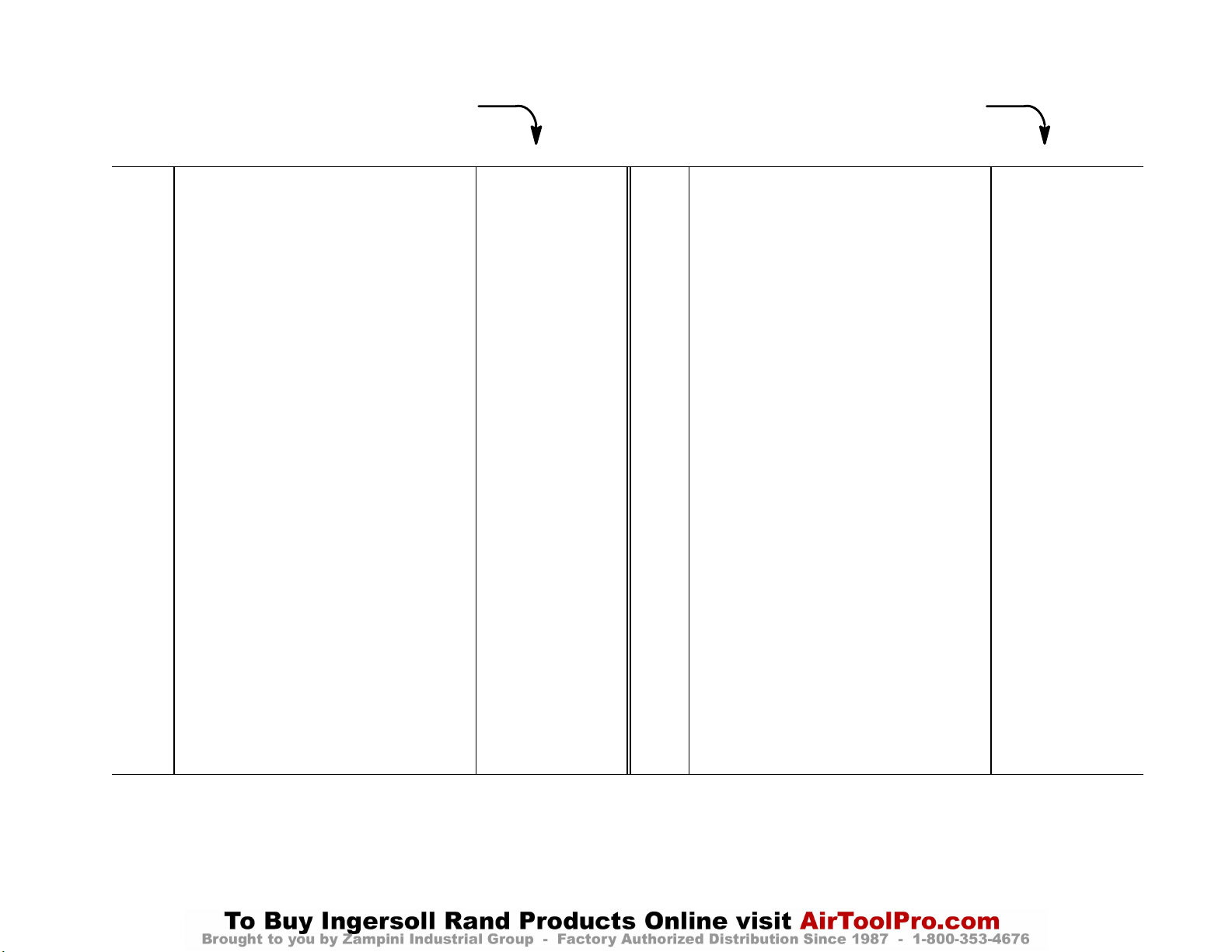
16
PART NUMBER FOR ORDERING PART NUMBER FOR ORDERING
* Nameplate 39 Belt Plate (for 12” x 1/2” and 18” x
for CA120 models ending in –EU.
for all other CA120 models . . . . .
. . . . . . .
for CA200 models ending in –EU. LA120–EU–301 1/2” and 18” x 1/2” models only) (2) . . . 40–25–74–5
for all other CA200 models . . . . . LA120–301 41 Belt Plate Spacer (for 12” x 1/2” and
Belt Sander Assembly 18” x 1/2” models only) (2) . . . . . . . . . . . LG1–361A
for 12” x 1/2” models . . . . . . . . . LG1–A350–812 42 Yoke
for 18” x 1/2” models . . . . . . . . . LG1–A350–818 for 12” x 1/2” and 18” x 1/2”
for 18” x 1/4” models . . . . . . . . . LG1–A350–418 models . . . . . . . . . . . . . . . . . . . . . LG1–354A
32 Spindle Cap . . . . . . . . . . . . . . . . . . . . . . . LG1–362 for 18” x 1/4” models . . . . . . . . . LG1–354–18–1/4
33 Drive Sleeve . . . . . . . . . . . . . . . . . . . . . . . LG1–358 43 Yoke Spring . . . . . . . . . . . . . . . . . . . . . . . LG1–355
34 Guard 44 Yoke Retaining Pin
for 12” models . . . . . . . . . . . . . . . LG1–357 for 12” x 1/2” and 18” x 1/2”
for 18” models . . . . . . . . . . . . . . . LG1–901 models . . . . . . . . . . . . . . . . . . . . . D92–152
35 Guard Clamp Screw . . . . . . . . . . . . . . . . . SRA010A1–68 for 18” x 1/4” models . . . . . . . . . 9DF5846–667
35A Alignment Block (for 18” 45 Idler Wheel Assembly
models only) . . . . . . . . . . . . . . . . . . . . . . LG1–902 for 12” x 1/2” and 18” x 1/2”
35B Cover (for 18” models only) . . . . . . . . . . LG1–900 models . . . . . . . . . . . . . . . . . . . . . LG1–A352A
36 Clevis Assembly for 18” x 1/4” models . . . . . . . . . LG1–A352–18–1/4
for 12” x 1/2” and 18” x 1/2” 47 Idler Wheel Bearing (2)
models . . . . . . . . . . . . . . . . . . . . . LG1–A351A for 12” x 1/2” and 18” x 1/2”
for 18” x 1/4” models . . . . . . . . . LG1–A351–18–1/4 models . . . . . . . . . . . . . . . . . . . . . 7AH–500
* Belt Speed Label . . . . . . . . . . . . . . . . LA1–98 for 18” x 1/4” models . . . . . . . . . LG1–365
37 Clevis Mounting Screw (2) 49 Idler Wheel Shaft
for 12” x 1/2” and 18” x 1/4” for 12” x 1/2” and 18” x 1/2”
models . . . . . . . . . . . . . . . . . . . . . LG1–634 models . . . . . . . . . . . . . . . . . . . . . R31–121
for 18” x 1/2” models . . . . . . . . . LG1–903 for 18” x 1/4” models . . . . . . . . . LG1–366
38 Belt Pad 50 Guard Clamp Screw
for 12” x 1/2” and 18” x 1/2” Wrench (5/32” hex) . . . . . . . . . . . . . . . . . 4U–478
models . . . . . . . . . . . . . . . . . . . . . LG1–363
for 18” x 1/4” models . . . . . . . . . LG1–364
* Not illustrated.
LA112–EU–301 1/2” models only) . . . . . . . . . . . . . . . . . . LG1–360
LA112–301 40 Belt Plate Retaining Screw (for 12” x
MAINTENANCE SECTION
Page 17
17
PART NUMBER FOR ORDERING PART NUMBER FOR ORDERING
* Sanding Belt Pack (includes 10 belts) 51 Collet Body Wrench (7/16” x 11/16”) . . . . . . DG20–69A
for 12” x 1/2” models 52 Clamp Nut Wrench . . . . . . . . . . . . . . . . . . . . LA2–253
60 Grit . . . . . . . . . . . . . . . . . . . . . LG1–SB812–60–10 53 Arbor Bearing Cap Wrench . . . . . . . . . . . . . . AG210–29
80 Grit . . . . . . . . . . . . . . . . . . . . . LG1–SB812–80–10 * Variable Speed Control Assembly
100 Grit . . . . . . . . . . . . . . . . . . . . LG1–SB812–100–10 (with piped away exhaust) . . . . . . . . . . . . . . . LG1–A1015
for 18” x 1/2” models * Piped Away Exhaust Kit . . . . . . . . . . . . . . . . LG1–K284
60 Grit . . . . . . . . . . . . . . . . . . . . . LG1–SB818–60–10
80 Grit . . . . . . . . . . . . . . . . . . . . . LG1–SB818–80–10
100 Grit . . . . . . . . . . . . . . . . . . . . LG1–SB818–100–10
for 18” x 1/4” models
60 Grit . . . . . . . . . . . . . . . . . . . . . LG1–SB418–60–10
80 Grit . . . . . . . . . . . . . . . . . . . . . LG1–SB418–80–10
100 Grit . . . . . . . . . . . . . . . . . . . . LG1–SB418–100–10
* Not illustrated.
MAINTENANCE SECTION
Page 18

MAINTENANCE SECTION
Always wear eye protection when operating or
performing maintenance on this tool.
Always turn off the air supply and disconnect the air
supply hose before installing, removing or adjusting
any accessory on this tool, or before performing any
maintenance on this tool.
DISASSEMBLY
General Instructions
1. Do not disassemble the tool any further than necessary to replace or repair damaged parts.
2. When grasping a tool or part in a vise, always use the
surface of the part or tool and help prevent distortion.
This is particularly true of threaded members and
housings.
3. Do not remove any part which is a press fit in or on a
subassembly unless the removal of that part is necessary for repairs or replacement.
4. Do not disassemble the tool unless you have a complete set of new gaskets and O–rings for replacement.
5. Do not press any needle bearing from a part unless
you have a new needle bearing on hand for installation. Needle bearings are always damaged during the
removal process.
Disassembly of the Sanding Arm
1. For 18” models, slide the Cover (35B) rearward toward the handle of the Sander until it is free. It may
require a light rap on the front edge of the Cover to
disengage it from its locking points.
2. Using the Guard Clamp Screw Wrench (50), loosen
the Guard Clamp Screw (35) and remove the Guard
(34) and assembled sanding arm from the Angle
Housing (22).
3. Using a screwdriver, remove the two Clevis Mounting
Screws (37) and separate the Clevis (36) from the
Guard.
4. For 12” x 1/2” and 18” x 1/2” models, use a screwdriver, to remove the two Belt Plate Retaining Screws
(40), two Belt Plate Spacers (41) and the Belt Plate
(39).
5. If the Belt Pad (38) must be replaced, peel the Pad
from the side of the Clevis or Yoke (42) and scrape
the surfaces clean.
6. To separate the Yoke from the Clevis, press the Yoke
Retaining Pin (44) out of the Yoke and Clevis with an
arbor press.
Be careful not to allow the compression of the Yoke
Spring (43) to expel the Yoke or Clevis in an unsafe
manner when the pressing plug is withdrawn from
the Yoke.
7. Press the Idler Wheel Shaft (49) out of the Yoke and
Idler Wheel (45).
8. The Idler Wheel contains an Idler Wheel Bearing (47)
at each end. Simultaneously press both Bearings out
of the Wheel.
Disassembly of the Angle Head
1. Grasp the tool in leather–covered or copper–covered
vise jaws with the Spindle Cap (32) upward. Using
the Collet Body Wrench (50) on the flats of the Arbor
(31), unscrew the Spindle Cap. If the Drive Sleeve
(33) needs replacement, cut the old one from the
Spindle Cap.
2. Using the Arbor Bearing Cap Wrench (53), unscrew
and remove the Arbor Bearing Cap (30). This is a
left–hand thread. Rotate the Cap Wrench clockwise
to remove the Cap.
3. Using the Clamp Nut Wrench (52), loosen the Clamp
Nut (24) and pull the Angle Housing Assembly (22)
away from the Motor Housing (5). This is a left–hand
thread. Rotate the Nut Wrench clockwise to loosen
the Nut.
Do not allow the Angle Head to rotate when separating it from the Motor. Components may fall
from the Angle Head.
4. Grasp the Arbor and pull the assembled Arbor out of
the Angle Head. If the Wick (27) needs replacement,
pull it out of the Angle Housing.
5. If the Upper Arbor Bearing (26) needs replacement,
place the Angle Head on the table of an arbor press,
arbor end down, and press the Bearing out of the
Angle Head.
18
Page 19
MAINTENANCE SECTION
6. Grasp the Arbor in leather–covered or copper–covered vise jaws with the collet end downward. Using
an adjustable wrench, unscrew and remove the Bevel
Gear Nut (28) and lift the Bevel Gear off the Arbor.
7. If the Lower Arbor Bearing (29) must be replaced,
use a piece of tubing to support the Bearing on the
table of an arbor press and press the Arbor from the
Bearing.
Disassembly of the Motor
1. Pull the Flange (19) and Flow Ring (18) off the front
of the Motor Housing (5).
2. Grasp the Bevel Pinion (21) and pull the assembled
motor out of the Motor Housing. Remove the two
Rear Rotor Bearing Spacers (10) from the bottom of
the Housing.
3. Remove the Vanes (13) from the Rotor (12).
4. Grasp the Rotor in leather–covered or copper–covered
vise jaws with the Bevel Pinion upward. Using a 1/2”
wrench, unscrew and remove the Bevel Pinion (21).
5. If the Front Rotor Bearing (17) must be replaced, support the Front End Plate (14) between two blocks on
the table of an arbor press. Place the blocks as close
to the body of the Rotor as possible and press the Rotor from the Bearing and End Plate. Remove the Front
End Plate Spacer (15) and Front Seal Assembly (16)
from the hub of the Rotor.
6. If the Rear Rotor Bearing (9) must be replaced, use
snap ring pliers to remove the Rear Rotor Bearing
Retainer (11) and then remove the two Rear Rotor
Bearing Spacers (10).
7. Using a bearing puller, pull the Rear Rotor Bearing
off the hub of the Rotor.
Disassembly of the Inlet and Throttle
6. Press the Throttle Lever Pin (7) from the Housing and
remove the Throttle Lever (6). Remove the Throttle
Valve Plunger (8).
ASSEMBLY
General Instructions
1. Always press on the inner ring of a ball–type bearing
when installing the bearing on a shaft.
2. Always press on the outer ring of a ball–type bearing
when pressing the bearing into a bearing recess.
3. Whenever grasping a tool or part in a vise, always use
leather–covered or copper–covered vise jaws. Take
extra care not to damage threads or distort housings.
4. Always clean every part and wipe every part with a
thin film of the recommended oil before installation.
5. Check every bearing for roughness. If an open bearing
must be cleaned, wash it thoroughly in a clean, suitable cleaning solution and dry with a clean cloth.
Sealed or shielded bearings should not be cleaned.
Work grease into every open bearing before installation.
6. Apply a film of O–ring lubricant to every O–ring
before installation.
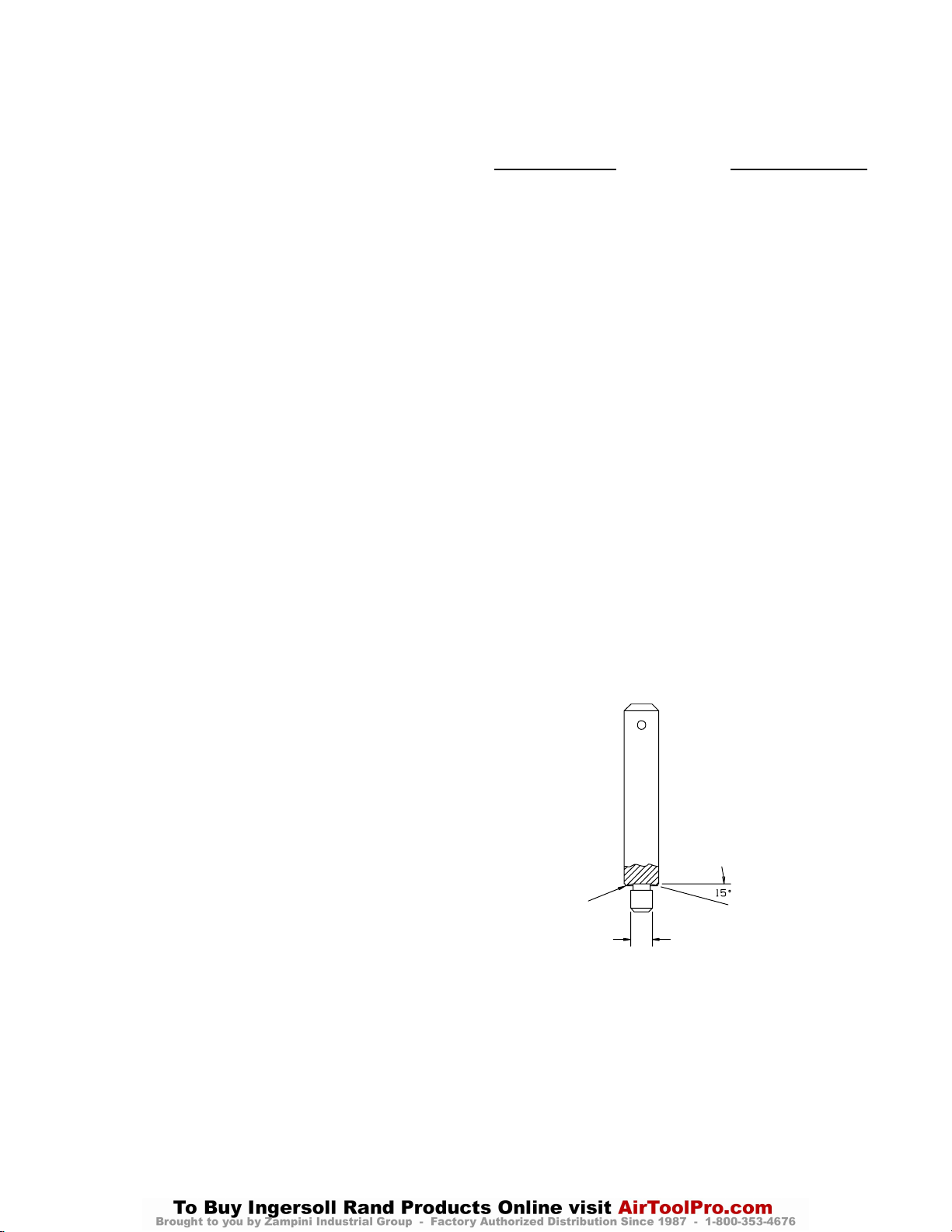
7. Unless otherwise noted, always press on the stamped
end of a needle bearing when installing a needle bearing into a recess. Use a bearing inserting tool similar
to the one shown in Dwg. TPD786.
NEEDLE BEARING INSERTING TOOL
1. Using a 3/4” wrench, unscrew and remove the Inlet
Assembly (1).
2. Remove the Inlet Seal (3) and Inlet Screen (2) from
the Inlet.
3. Remove the Throttle Valve Spring Seat (4D), Throttle
Valve Spring (4C) and Throttle Valve (4B) from the
Motor Housing.
4. If the Throttle Valve Seat (4A) must be replaced, insert a hooked tool through the central opening of the
Seat and, catching the underside of the Seat, pull it
from the Housing.
5. If the Throttle Valve Cartridge Case (4) must be replaced, insert two hooked tools through the central
opening of the Case approximately 180 degrees apart
and, catching the underside of the Case, pull it from
the Housing.
19
SHOULDER TO
REGULATE DEPTH
PILOT TO FIT I.D. PF BEARING. LENGTH OF PILOT TO
BE APPROXIMATELY 1/8”
LESS THAN LENGTH OF
BEARING,
(Dwg. TPD786)
Page 20

MAINTENANCE SECTION
Assembly of the Throttle and Inlet
1. Insert the Throttle Valve Plunger (8) into the Motor
Housing (5).
2. Position the Throttle Lever (6) on the Motor Housing
and using an arbor press, press the Throttle Lever Pin
(7) into the Housing and Lever. The Lever will retain
the Plunger in the Housing.
3. If the Throttle Valve Cartridge Case (4) was removed,
lubricate the outside and the throttle stem end of the
Case with O–ring lubricant. Using a wooden dowel,
push the Case, open end trailing, into the Motor Housing.
4. If the Throttle Valve Seat (4A) was removed, use a
wooden dowel with a flat end to push the Seat into the
Case.
5. Push the small end of the Throttle Valve Spring (4C)
onto the end of the Throttle Valve (4B) with the short
stem until the Spring snaps into position around the
hub and remains there. Install the dish end of the
Throttle Valve Spring Seat (4D) onto the large end of
the Throttle Valve Spring.
6. Holding the Housing with the Lever downward, make
sure the Plunger is out of the way and insert the assembled Valve, long stem end leading, into the Cartridge Case.
7. Push the Inlet Screen (2), closed end leading, into the
Inlet Assembly (1). After moistening the Inlet Seal
(3) with O–ring lubricant and being careful not to
nick the Seal on the threads of the Inlet, install the
Seal on the Inlet.
8. Thread the Inlet Assembly into the Housing and tighten it between 13 to 15 ft–lb (17.6 to 20.3 Nm) torque.
Assembly of the Motor
1. If the Rear Rotor Bearing (9) was removed, stand the
Rotor (12) upright on the table of an arbor press with
the threaded end downward. Place the threaded rotor
hub into a hole of a drilled block so that the Rotor
rests against the large rotor body. Press the Rear Rotor
Bearing onto the hub of the Rotor.
4. Stand the Rotor on the table of an arbor press with the
threaded end upward and press the Front Rotor Bearing (17) onto the hub of the Rotor.
The Front Rotor Bearing is a double flush ground
bearing and must be installed in a specific manner.
The end of the Bearing with a black stain or hash
marks must be away from the Spacer.
5. Grasp the assembled Rotor in leather–covered or
copper–covered vise jaws with the threaded rotor hub
upward.
6. Thread the Bevel Pinion (21) onto the Rotor and using
a torque wrench, tighten the Bevel Pinion between 9
and 10 ft–lb (12.2 and 13.6 Nm) torque.
7. Inject approximately 0.7 cc of Ingersoll–Rand No. 68
Grease into the small recess at the bottom of the motor housing bore. Drop the two Rear Rotor Bearing
Spacers (10) into the bottom of the motor housing
bore.
8. Wipe each Vane (13) with a light film of oil and insert
a Vane into each vane slot in the Rotor.
9. Grasp the Bevel Pinion and insert the assembled
Rotor into the Motor Housing (5).
10. Assemble the Flow Ring (18) with the Flange (19)
before installing the Flange on the housing. Mate the
Flow Ring to the end of the Flange without perforations. The positioning of the flow Ring is dictated by
the desired exhaust. To set the tool exhaust, proceed
as follows:
a. For front exhaust tools, align the notched
projection on the edge of the Flow Ring with the
letter “F” on the Housing.
b. For rear exhaust tools, align the notched
projection on the edge of the Flow Ring with the
letter “R” on the Housing.
11. Install the assembled Flange, Flow Ring leading, onto
the front of the Motor Housing.
Assembly of the Angle Head
Press the Rotor Bearing onto the shaft with the
shielded side of the Bearing against the rear end
plate.
2. Install the Rear Rotor Bearing Retainer (11) in the
groove on the hub of the Rotor.
3. Place the Front End Plate Spacer (15) onto the
threaded hub of the Rotor and install the Front End
Plate (14) around the Spacer, counterbored end trailing. Press the Front Seal Assembly (16), felt end trailing, onto the Spacer until the trailing end is flush with
the Spacer. Lubricate the felt with Ingersoll–Rand
No. 50 Oil.
1. If the Upper Arbor Bearing (26) was removed and a
new Bearing must be installed, proceed as follows:
a. Support the machined face of the Angle Head (22)
on the table of an arbor press with the upper arbor
bearing bore upward.
b. Press a new Upper Arbor Bearing into the bore,
flush with the top of the Angle Housing.
Always press on the stamped or closed end of
the Bearing.
20
Page 21
MAINTENANCE SECTION
2. If the Lower Arbor Bearing (29) is being installed, it
is necessary to note the identification marks on the
Lower Arbor Bearing. The side of the Bearing having
black stains or black hash marks on the side of the
inner and outer races is opposite the flush ground
side.
3. Using your hand, push the Lower Arbor Bearing,
flush ground side inward, into the recess at the machined end of the Angle Head.
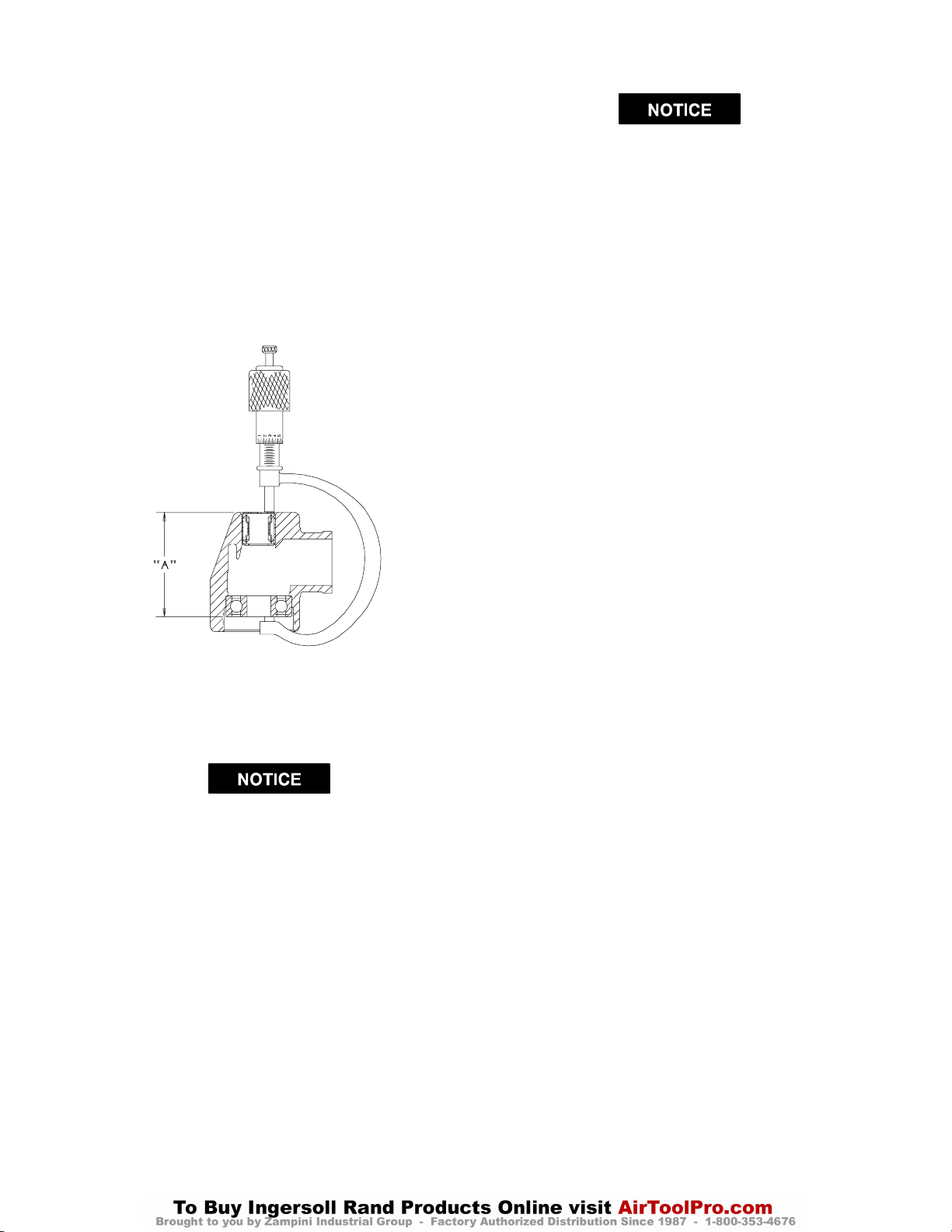
4. Using a 2” micrometer, take a measurement from the
inner ring of the Lower Arbor Bearing to the stamped
or closed end of the Upper Arbor Bearing.
See Dwg. TPD687.
Minimum
Dimension
“A”
in mm
1.36 34.65
5. Additional pressing of the Upper Arbor Bearing may
be required to finally attain the correct dimension as
indicated in the table above.
6. Remove the Lower Arbor Bearing.
In the following step, make certain any shims included with the Lower Arbor Bearing are installed
onto the Arbor between the Bevel Gear (21) and
the Bearing.
7. Using a sleeve that contacts the inner ring of the Lower Arbor Bearing, press the Bearing, flush ground
side of the Bearing trailing onto the Arbor (31).
8. Slide the Bevel Gear, geared face trailing, onto the
small threaded end of the Arbor, aligning the integral
keys of the gear with the slotted keyways in the
Arbor.
Maximum
Dimension
“A”
in mm
1.38 35.00
(Dwg. TPD687)
The Bevel Gear and Bevel Pinion are specially
matched sets. Replace these parts only as a
matched set.
9. Thoroughly clean the small threads on the Arbor
above the Bevel Gear and the threads in the Bevel
Gear Nut (28).
10. Apply a thin coat of Permalock HM118* to the
threads of the Bevel Gear Nut and the Nut threads on
the Arbor. Thread the Bevel Gear Nut onto the Arbor
to retain the Bevel Gear and tighten the Nut to 10 to
12 ft–lb (13.5 to 16.2 Nm) torque. Grease the Bevel
Gear with 1.5 cc of Ingersoll–Rand No. 67 Grease.
11. Form the Wick (27) into a horseshoe shape and insert
it into the Angle Head. Push the Wick into the opening until it is compressed approximately 0.030” below
the bevel gear bore. Soak the Wick with approximately 1.5 cc of Ingersoll–Rand No. 63 Oil. Do no substi-
tute any other oil.
12. Carefully grasp the assembled motor in leather– covered or copper–covered vise jaws with the Throttle
Lever downward.
13. Install the motor Clamp Nut (24), threaded end trailing, onto the motor end of the Angle Head. Spread the
Clamp Spacer (23) and install it on the motor end of
the Angle Head against the Clamp Nut.
14. Position the output end of the Angle Head upward and
opposite with the Throttle Lever and thread the
Clamp Nut onto the Motor Housing. Using the Clamp
Nut Wrench (52), tighten the Nut to 20 to 25 ft–lb
(27 to 34 Nm) torque. This is a left–hand thread, turn
counterclockwise to tighten.
15. Insert the assembled Arbor into the Angle Head, bevel
gear end first, making sure the teeth on the Bevel
Gear and Pinion mesh. Rotate the Arbor manually to
determine that they are rotating smoothly.
16. Thoroughly clean the internal threads of the Angle
Head and the threads on the Arbor Bearing Cap (30).
17. Carefully apply a uniform coat of Vibra–Tite VC3
No. 205 ** to both sets of threads and allow the compound to cure for 10 to 20 minutes.
18. Using the Arbor Bearing Cap Wrench (53), install the
Arbor Bearing Cap and tighten to 12 to 15 ft–lb (16.2
to 20.3 Nm) torque. The Bearing Cap has a left–hand
thread: turn counterclockwise to install.
* Product of National Starch and Chemical Corporation.
** Product of N.D. Industries.
21
Page 22

MAINTENANCE SECTION
19. If the Drive Sleeve (33) is being replaced, slide a new
Sleeve onto the Spindle Cap (32) until it is captured
between the two outer lipped edges.
20. Using the Collet Body Wrench (50) to hold the Arbor,
install the Spindle Cap onto the Arbor.
Assembly of the Sanding Arm
In the following step, ball bearings used in models
having 1/4” wide belts must have the bearing seal
facing outward.
1. If the Idler Wheel Bearings (47) were removed, press
one Bearing into the Idler Wheel (45) until it is flush
with the edge of the Wheel. Invert the Wheel. Press
the remaining Bearing into the Wheel until it is flush
with the edge of the Wheel.
In the following step, one hole in the Yoke is
slightly larger than the other one. Determining
which hole is larger will enable you to use finger
pressure to insert the Shaft through that side of the
Yoke.
2. Position the assembled Idler Wheel between the two
ears of the Yoke (42) and press the Idler Wheel Shaft
through the Yoke and assembled Idler Wheel.
3. For 12” x 1/2” and 18” x 1/2” models, place the
Yoke Spring (43) into the hole in the end of the Clevis
(36) and position the assembled Yoke over the Spring
at the end of the Clevis. Make certain the slots in the
Yoke align with the pin hole in the Clevis. Compress
the Spring with the Yoke and press the Yoke Retaining Pin (44) through the Clevis and Yoke.
For 18” x 1/4” models, place the Yoke Spring (43)
inside the end of the Yoke opposite the Idler Wheel
until it stops against the tab. Position the Clevis (36)
to slide into the Yoke making certain the Spring enters
the slot in the end of the Clevis. Make certain the slot
in the Yoke aligns with the pin hole in the Clevis.
Compress the Spring with the Yoke and press the
Yoke Retaining Pin (44) through the Clevis and Yoke.
4. For 12” x 1/2” and 18” x 1/2” models, insert one of
the Belt Plate Retaining Screws (40) through one of
the holes in the Belt Plate (39). Install one of the Belt
Plate Spacers (41) on the Screw and start the Screw
into the Clevis at the guard end. Insert the remaining
Screw into the hole in the Plate at the yoke end and
install the remaining Spacer on that Screw between
the Plate and Clevis. Tighten both Screws hand tight
with a screwdriver.
5. If the Belt Pad (38) is being replaced, peel the protective tape off the Pad and place the adhesive side of the
Pad against the side of the Clevis opposite the Belt
Plate.
6. For 12” models, using a screwdriver, attach the
Clevis to the Guard (34) with the two Clevis Mounting Screws (37). Tighten the Screws between 8 and
10 in–lb. (0.9 and 1.1 Nm) torque.
For 18” models, position the Alignment Block (35A)
between the Clevis and the Guard (34) and secure it in
position by attaching the Clevis to the Guard with the
two Clevis Mounting Screws (37). Tighten the
Screws between 8 and 10 in–lb. (0.9 and 1.1 Nm)
torque.
7. Position the Guard (34) on the Angle Head (22) and
secure it by tightening the Guard Clamp Screw (35)
between 2 and 3 ft–lb (2.7 and 4.0 Nm) torque.
8. Install a new sanding belt over the Spindle Cap and
around the Idler Wheel.
9. For 18” models, align the Cover (35B) with the
Guard and slide it forward toward the Idler Wheel
until it snaps into position and stays there.
10. Operate ths Sander at low speed to determine if the
new belt is tracking properly. If the belt fails to track
properly, realign the Clevis by tightening or loosening
one or both of the Clevis Mounting Screws.
22
Page 23

MAINTENANCE SECTION
TROUBLESHOOTING GUIDE
Trouble Probable Cause Solution
Low power or low free speed Insufficient air pressure Check air line pressure at the Inlet of the tool. It must
be 90 psig (6.2 bar/620 kPa).
Clogged muffler elements Disassemble the tool and agitate the bare Motor
Housing and Flange in a clean, suitable cleaning solution. If the elements cannot be cleaned, replace the
Motor Housing and/or the Flange.
Plugged Inlet Screen Clean the Inlet Screen in a clean, suitable, cleaning
solution or replace the Screen.
Worn or broken Vanes Install a complete set of new Vanes.
Loose Clamp Nut Tighten the Nut to 20 to 25 ft–lb (27 to 34 Nm) torque.
Worn or broken Motor Housing Replace the Motor Housing.
Internal air leakage in the Motor
Housing indicated by high air consumption/low speed or air leaking
out the front and rear exhaust
simultaneously.
Grit buildup under the Throttle
Lever restricting full Throttle
Valve Plunger movement.
Bent stem on Throttle Valve Replace the Throttle Valve
Front Seal Cup dragging against
the shield of the Front Rotor Bearing
Replace the Motor Housing.
Remove the Throttle Lever and clean the groove in
the Motor Housing.
Reposition or replace the Front Seal Cup.
Scoring Worn Front End Plate Spacer or
Front End Plate
Worn Front Rotor Bearing Install a new Front Rotor Bearing.
Sanding Belt not tracking Worn Idler parts Install a new Idler Wheel Assembly
Misalignment Adjust the Clevis Mounting Screws
Sanding on push side of Clevis Sand on pull side of the Clevis.
Install a new Front End Plate Spacer and Front End
Plate.
23
Page 24

MAINTENANCE SECTION
TROUBLESHOOTING GUIDE
Trouble Probable Cause Solution
Leaky Throttle Valve Dirt accumulation on Throttle
Valve or Valve Seat
W orn Throttle Valve or V alve Seat Replace the Throttle Valve and/or Throttle Valve
Exhausts at wrong location Incorrect orientation of the Flow
Ring
Front Rotor Bearing runs hot Incorrect installation of the Front
Seal Cup
Front End Plate Spacer rubbing th e
bore of the Front End Plate
Incorrect Front Rotor Bearing
installation orientation
Slow tool idle Bent or leaky Throttle Valve Replace the Throttle Valve.
Air leakage around Flow Ring Damaged, mutilated or missing
Flange Clamp
Damaged Flow Ring Replace the Flow Ring
Rough operation/vibration Improper lubrication or dirt build-upDisassemble the tool and clean in a clean, suitable,
Worn or broken Rear Rotor
Bearing or Front Rotor Bearing
Worn or broken Upper Arbor
Bearing or Lower Arbor Bearing
Worn or broken Bevel Gear or
Bevel Pinion
Disassemble, inspect and clean parts.
Seat.
Reverse the face of the Flow Ring against the Motor
Housing.
Reposition the Front Seal Cup flush with the face of
the Front End Plate Spacer.
Replace the Front End Plate and Front End Plate
Spacer combination.
If a black stain or black hashmarks are not visible on
the face of the Bearing when it is assembled with the
End Plate and Rotor, the Bearing is backwards.
If possible, remove the Bearing and install it correctly
or replace the Bearing.
Replace the Flange Clamp.
cleaning solution. Assemble the tool and inject 3 cc
of the recommended oil into the Inlet and run the
Sander long enough to coat the internal parts with the
oil.
Replace the worn or broken Bearings. Examine the
Front End Plate, Front End Plate Spacer, Front Seal
Cup and Rear Rotor Bearing Spacers and replace any
damaged parts. If the rear end plate is damaged,
replace the Rotor.
Replace the worn or broken Bearing.
Examine the Bevel Gear and Bevel Pinion. If either
is worn or damaged, replace both the Gear and Pinion
because they are a matched set and must not be used
separately.
SAVE THESE INSTRUCTIONS. DO NOT DESTROY.
24
 Loading...