

Ingersoll-Rand 6546X-X, ARO 65440, ARO 65442-B, ARO 65444-2-B, ARO 65462 Operator's Manual
...Page 1
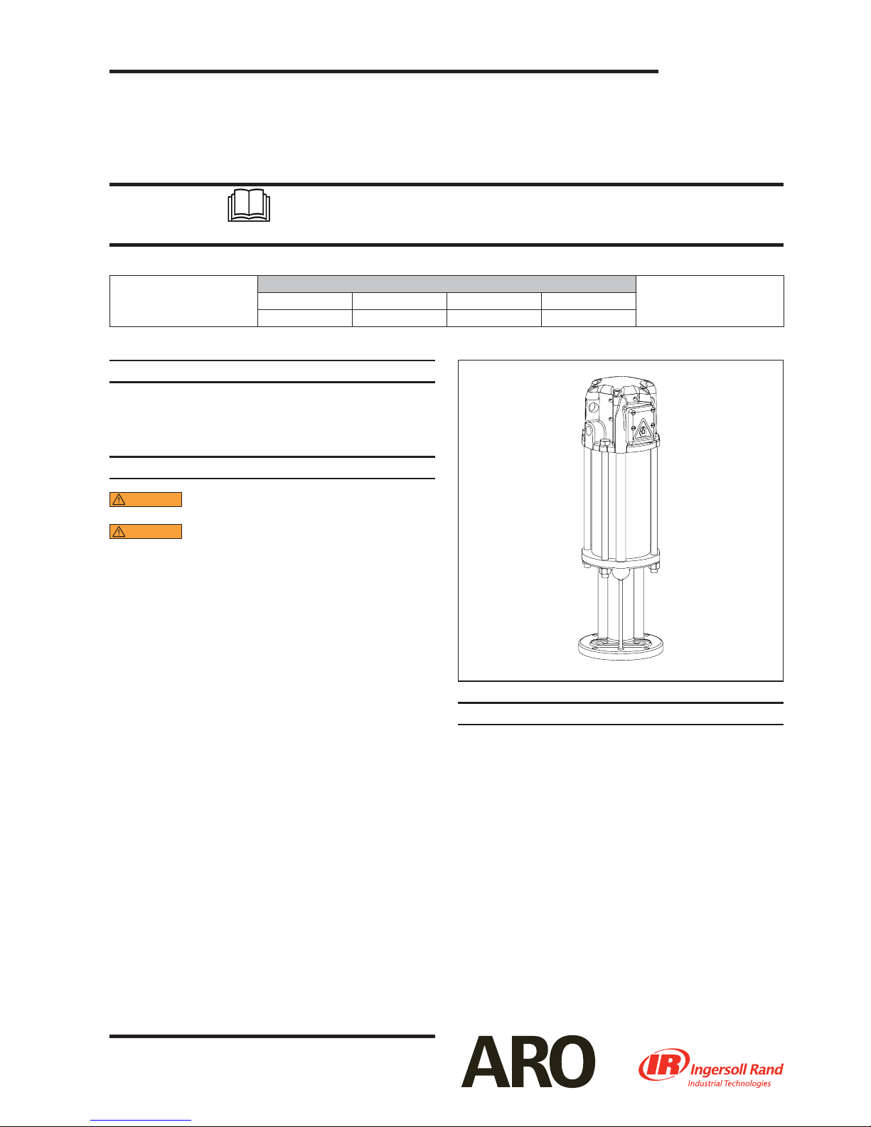
OPERATOR’S MANUAL 6544X-X
INCLUDING: SERVICE KITS, TROUBLESHOOTING, PARTS LIST,
6546X-X
DISASSEMBLY & REASSEMBLY.
4-1/4” AIR MOTORS
6544X-X (4” STROKE) and 6546X-X (6” STROKE)
Also covers 61268 service kits
READ THIS MANUAL CAREFULLY BEFORE INSTALLING,
OPERATING OR SERVICING THIS EQUIPMENT.
It is the responsibility of the employer to place this information in the hands of the operator. Keep for future reference.
THIS MANUAL COVERS THE FOLLOWING MODELS
MODEL
65440 65442-B 65444-2-B 65462
65441-B 65444-B 65445-B 65465-B
Also covers obsolete and cancelled models: 61777, 65420-1, 65443-B, 65443-2-B, 65444-1B, 65465-1-B and 65466.
SERVICE KITS
Use only genuine ARO® replacement parts to assure com-
patible pressure rating and longest service life.
61268 for general repair of all 4-1/4” air motors.
RELEASED: 2-26-82
REVISED: 11-28-07
(REV. U)
GENERAL DESCRIPTION
WARNING
PRESSURE AS INDICATED ON PUMP MODEL PLATE.
WARNING
FOR ADDITIONAL SAFETY PRECAUTIONS AND IMPORTANT INFORMATION.
This manual only covers the air motor section. It is one of
four documents which support an ARO pump. Replacement copies of these forms are available upon request.
650XXX-X Pump Model Operator’s Manual.
General Information for Air Operated or Hydraulically
Lower Pump End Operator’s Manual.
Air or Hydraulic Motor Operator’s Manual.
The 4-1/4” air motor is a general purpose power unit and
is used with many 2-ball, 4-ball and chop check pumps. It
utilizes tie rod type construction for easy breakdown and
it connects to the various lower ends via tie rods for easy
operation. Consult pump model operator’s manual for
speci c instructions. It is recommended that a mu er be
connected to the exhaust port to reduce noise to acceptable OSHA standards.
Filtered and oiled air will allow the air motor to operate
more e ciently and yield a longer life to operating parts
and mechanisms. A filter capable of filtering particles
larger than 50 microns should be used with an oiler. Keep
the oiler supplied with a good grade of S.A.E. no. 90W
non-detergent gear oil, set at a rate not to exceed 1 or 2
drops per minute.
NOTICE: Do not operate the air motor above the recommended air pressure of 150 p.s.i. (10.3 bar) or 75 cycles
per minute. The air motor may be rated di erently in the
next assembly. Check the pump model plate.
DO NOT EXCEED MAXIMUM OPERATING
REFER TO GENERAL INFORMATION SHEET
Operated Pumps.
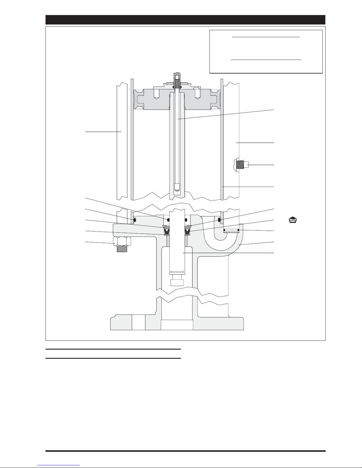
Figure 1
MAINTENANCE
The air / hydraulic motor is completely separate from the
lower pump end. This helps to keep the motor from being
contaminated by the material being pumped. Periodically,
ush entire pump system with a solvent that is compatible
with the material being pumped.
Keep solvent cup lled with this compatible solvent. This will
keep material from drying on the piston rod, which would
drag thru the packings, ruin them and eventually scour the
piston rod.
Provide a clean work surface to protect sensitive internal
moving parts from contamination from dirt and foreign matter during disassembly and reassembly.
Before reassembling, lubricate parts as required. When assembling “O” rings, or parts adjacent to “O” rings, exercise
care to prevent damage to “O” rings and “O” ring groove surface.
INGERSOLL RAND COMPANY LTD
P.O. BOX 151 ONE ARO CENTER BRYAN, OHIO 43506-0151
(800) 276-4658 FAX (800) 266-7016
© 2007 CCN 81582769
Page 2
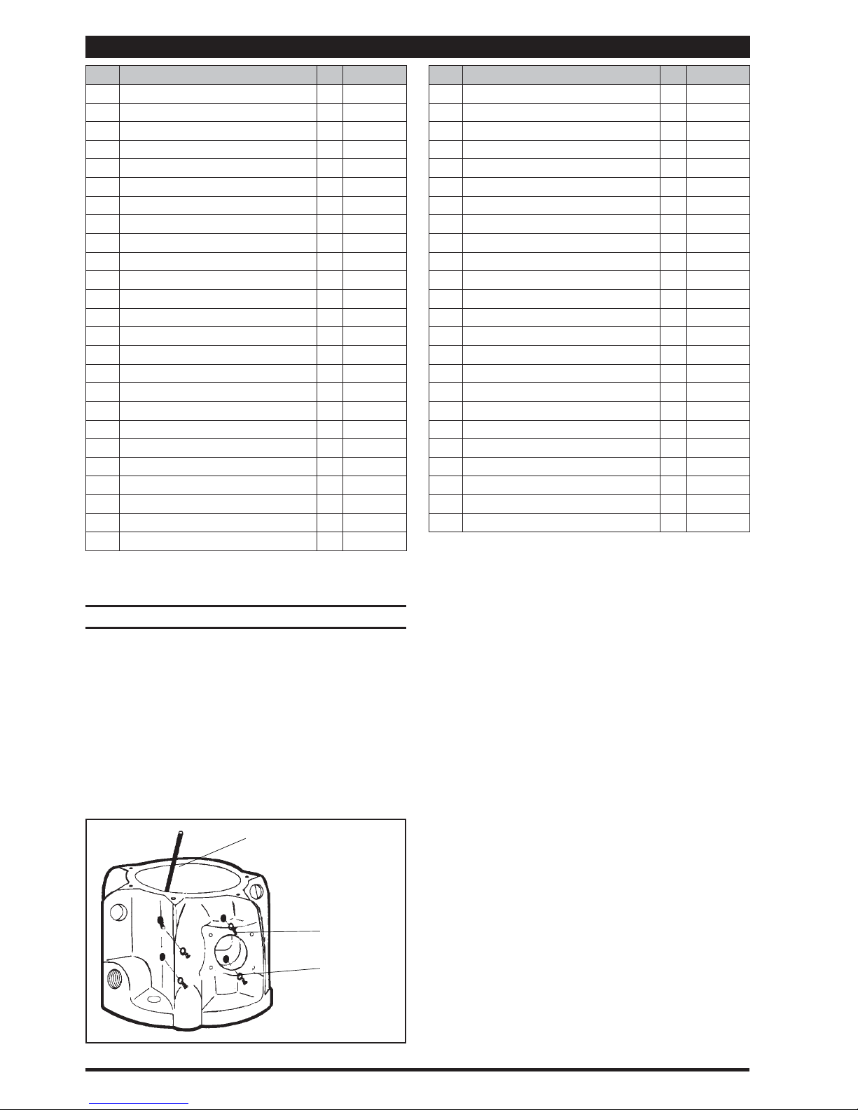
PARTS LIST / 6544X-X & 6546X-X
Item Description
1 Screw
2 De ector
3 Screw
4 Screw
5 Washer (4) 90084
6 Screw
7 Washer
8 Air Motor Cap (1) 90078
9 Valve Guide (1) 90093
10 Gasket (1) 90083-1
11 Insert (1) 90097
12 Valve Plate and Pin Assembly (1) 65028
12a Roll Pin
13 Insert Spring Assembly (1) 65032
14 Valve Insert (1) 90796
15 Gasket (1) 90091
16 “O” Ring
17 Washer (1) 91344
18 “O” Ring
19 Head Assembly (1) 65889
20 “U” Cup
21 “O” Ring
22 Screw
24 Piston Assembly (1) 61851
27 Rod Assembly
“Smart Parts”, keep these items on hand in addition to the service kits
for fast repair and reduction of downtime.
Includes item (12a) roll pin (qty 2).
(size)
(#8 - 32 x 7/8”) (not shown)
(not shown)
(#10 - 24 x 1/2”)
(#8 - 32 x 3/4”)
(1/4” - 28 x 3/4”)
(1/4” i.d.)
(3/32” o.d. x 3/4” long)
(1/16” x 1-3/8” o.d.)
(1/16” x 3/4” o.d.)
(3/16” x 1-3/8” o.d.)
(1/8” x 4-1/4” o.d.)
(#8 - 32 x 3/8”)
(see chart, page 4)
DISASSEMBLY OF AIR MOTOR
NOTE: All threads are right hand.
Place motor in up stroke position. This can be accom-
1.
plished by pushing (48) rod toward the top of the air
motor.
Remove four (1) screws from (2) de ector.
2.
Remove (2) de ector.
3.
Remove six (3) screws from (8) air motor cap.
4.
Remove (8) air motor cap and (10) gasket.
5.
Loosen four (4) screws (which hold (12) valve plate and
6.
(9) valve guide) until (9) valve guide can be removed by
pulling upward (see gure 9, page 6).
Allen Wrench
(Use an Allen wrench to
push out screws and
washers as shown.)
Page 2 of 8 6544X-X (en)
(Qty) Part No.
(4) Y136-90-S
(1) 90409
(6) 95956827
(4) Y19-89-S
(2) Y119-49-C
(2) Y14-416
(2) Y178-26-S
(2) Y325-26
(2) Y325-16
(1) Y186-51
(2) Y325-242
(4) Y136-85-S
(1) - - - - -
4 Screws (4)
5 Washers (4)
Figure 2
Item Description
28 Cylinder
29 Tube
30 Base and Bearing Ass’y
31 Valve Piston (1) 92394
32 Washer (1) 90105
33 Gland (1) 91006
34 Seal (1) 91007
35 “O” Ring
36 Extension Rod (1) 90080
38 Adapter (1) 92393
39 Gland (1) 90114
40 Washer (1) 91345
41 “O” Ring
42 Bolt
43 Snap Ring
44 Washer
45 “U” Cup
46 Washer
47 Nut
48 Piston Rod
49 “O” Ring
50 Ground Lug (1) 93006
51 Ground Label
Items included in Service Kit 61268
Remove four (4) screws and four (5) washers from (19)
7.
(size)
(see chart, page 4)
(see chart, page 4)
(0.103” x 1.255” o.d.)
(1/16” x 7/16” o.d.)
(see chart, page 4)
(see chart, page 4)
(see chart, page 4)
(see chart, page 4)
(see chart, page 4)
(see chart, page 4)
(see chart, page 4)
(see chart, page 4)
(not shown)
(see chart, page 4)
(Qty) Part No.
(1) - - - - -
(1) - - - - -
(1) - - - - -
(1) 91207
(1) Y325-11
(4) - - - - -
(1) - - - - -
(1) - - - - -
(1) - - - - -
(1) - - - - -
(4) - - - - -
(1) - - - - -
(1) - - - - -
(1) 93007
head assembly by pressing outward with a small allen
wrench, as illustrated in gure 2.
With the aid of a screwdriver, unhook the legs of (13) in-
8.
sert spring assembly from the bottom of (12) valve plate.
Remove (12) valve plate and (13) insert spring assembly
9.
from (19) head by pulling upward. If (12) valve plate is
stuck, tap the top edge lightly with a soft face mallet. Do
not tap with anything metallic.
Remove both (11 and 14) inserts and (13) insert spring
10.
assembly from (12) valve plate.
Remove (15) gasket from (19) head assembly.
11.
Remove two (6) screws and two (7) lock washers from
12.
(33) gland in (19) head assembly.
With fingers, pull (31) valve piston upward until (33)
13.
gland has pulled out of its chamber.
Remove (33) gland by sliding it up over (31) valve piston.
14.
Remove (34) seal and (35) “O” ring from (33) gland (see
15.
gure 8, page 6).
Disassemble (31) valve piston from (38) adapter as
16.
shown in gure 4, page 3.
Pull (38) adapter upward until assembly is taut and
17.
grasp (36) extension rod with ngers, as shown in gure
9, page 6. Grasp (36) extension rod below (38) adapter.
Now push (38) adapter down on (36) extension rod and
remove (32) washer from (36) extension rod. Now remove (38) adapter.
Remove (17) washer and (20) “U” cup from (38) adapter.
18.
Remove four (47) nuts from four (42) bolts.
19.
Remove four (42) bolts.
20.
Remove (19) head assembly and place on the work-
21.
bench with (8) cap side down. This action will allow (40)
washer to fall out of its cavity.
(continued on page 5)
Page 3
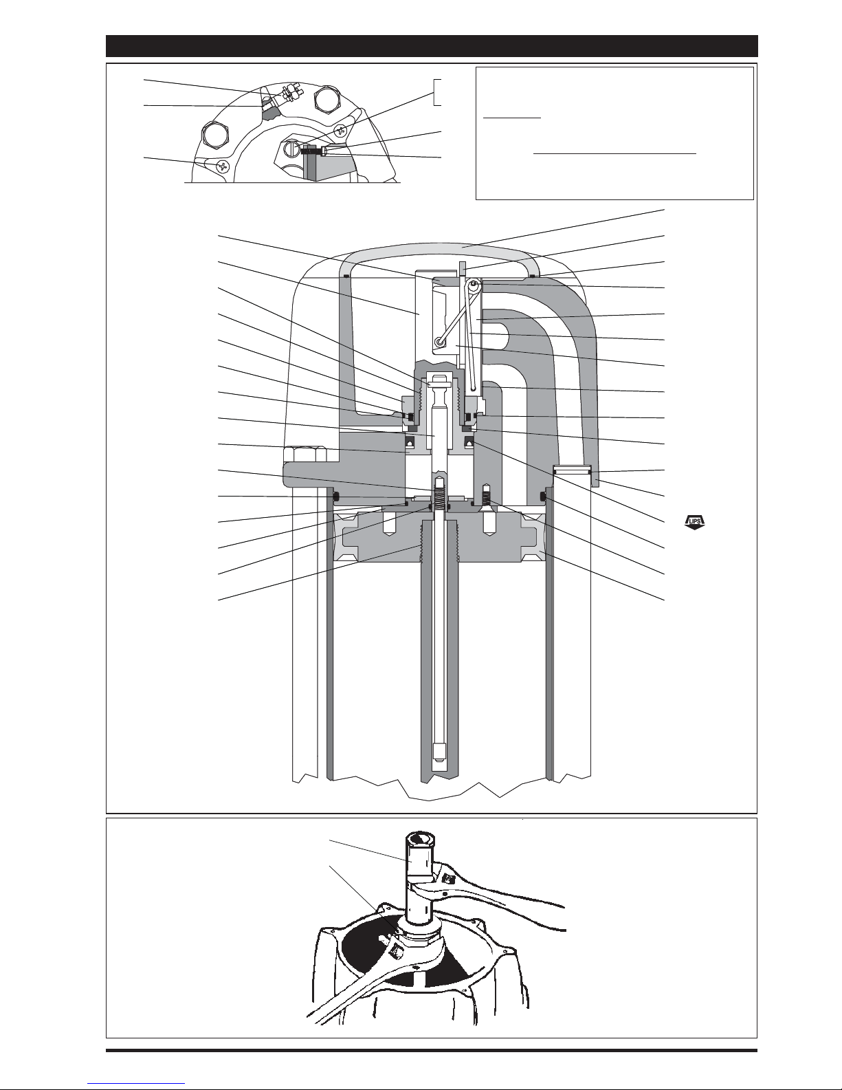
PARTS LIST / 6544X-X & 6546X-X - (AIR MOTOR HEAD)
50
50
Part numbers listed below and on parts list (opposite
6
6
7
7
4
4
5
3
3
11
11
31
31
32
32
33
33
34
34
35
35
36
36
38
38
5
page) are typical.
NOT SHOWN
93897-1 Pipe Plug (models 65440 only)
LUBRICATION / SEALANTS
NOTE: Lubricate with Parker “O” ring lube (ARO p/n
36460).
Apply Loctite® 271 to threads.
8
8
9
9
10
10
12a
12a
12
12
13
13
14
14
15
15
16
16
17
17
18
18
40
40
16
16
39
39
41
41
271™ is a trademark of Henkel Loctite Corporation
ARO® is a registered trademark of Ingersoll Rand Company
Loctite®is a registered trademark of Henkel Loctite Corporation
31
38
19
19
20
20
21
21
22
22
24
24
Figure 3
6544X-X (en) Page 3 of 8
Figure 4
Page 4
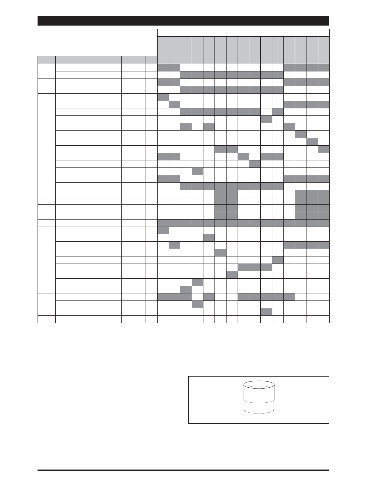
PARTS LIST / 6544X-X & 6546X-X
¾
AIR MOTOR MODEL NO.
Item Description
Rod Assembly 90107-1
27
(size)
Part No. (Qty)
Rod Assembly 90107-2
Cylinder 90090-1
28
Cylinder 90090-2
Tube 79008
29
Tube 90101-1
Tube 90101-2
Tube 94988
Base and Bearing
30
Base and Bearing
(Stub)
(Stub)
65020
65023
Base and Bearing 65023-2
Base and Bearing 65025
Base and Bearing
Base and Bearing
Base and Bearing
(1/2” - 20 x 10-1/4”)
Bolt
42
(1/2” - 20 x 8-1/4”)
Bolt
43 Snap Ring
44 Washer 73986
45 U” Cup
46 Washer 90103
47 Nut
48
49
(1/2” - 20)
(see page 8)
Rod
(see page 8)
Rod
(see page 8)
Rod
(see page 8)
Rod
(see page 8)
Rod
(see page 8)
Rod
(see page 8)
Rod
(see page 8)
Rod
(see page 8)
Rod
O” Ring
O” Ring
(1/4” x 1-1/4” o.d.)
(1/8” x 1” o.d.)
(1/8” x 1-5/8” o.d.)
52 Pipe Plug
Items included in Service Kit 61268
Indicates where parts are used.
Indicates models no longer active, shown for reference only.
“Smart Parts”, keep these items on hand in addition to the service kits
(Stub)
(Stub)
(Stub)
(1.456” o.d.)
(1/8” - 27 N.P.T.)
65775
65775-2
90074
94046-1 (4)
94046-2 (4)
Y147-131
Y186-16
Y11-8-C (4)
61776
90082
90108-1
65911-2
90573
90595
66628
93289
93964
Y325-210
Y325-220
Y17-10-C
for fast repair and reduction of downtime.
¾
See model plate on (30) base for number.
On model 65440 and 65462 air motors, a plate is mounted on the bot-
tom of the (30) base. Therefore, the following parts are different and
illustrated on page 8.
93310 Bushing
93311 Retainer
93312 Guide
93313 Plate (note the orientation of the plate with the air inlet)
93958 Plate (note the orientation of the plate with the air inlet)
Y6-66-C Screw (4 req’d)
Y14-616-C Lock Washer (4 req’d)
NOTE: Base styles and lower packings may vary from that
shown on the cover. Refer to model number in the chart
above.
61777 65420-1 65440
For simplification of ordering and stocking, a Y325-210 “O”
ring, Y325-220 “O” ring and a Y186-16 “U” cup will be included
in 61268 service kit. When repairing the motor, use only the
one that is needed.
All of the service parts are the same for all motors except the
lower piston rod packing.
NOTE: It is highly recommended that a 90350 installation
tool be used. This will greatly ease installation of (38) adapter
and piston valve and will reduce the chances of damage to
the (20) “U” cup. A damaged (20) “U” cup can usually lead to
air motor failure.
65441-B
65442-B
65443-B 65443-2B 65444-B
65444-1B 65444-2-B
90350 INSTALLATION TOOL
65445-B
65462
65465-B
65465-1B 65466
Page 4 of 8 6544X-X (en)
Page 5
PARTS LIST / 6544X-X & 6546X-X - (AIR MOTOR PISTON ROD AND BASE)
See chart on the opposite page for each model.
42
49
TORQUE REQUIREMENTS
NOTE: DO NOT OVERTIGHTEN FASTENERS.
Tighten (48) rod to 50 - 60 ft lbs. (67.8 - 81.3 Nm).
LUBRICATION / SEALANTS
NOTE: Lubricate with Parker “O” ring lube (ARO p/n
36460).
27
29
52
28
21
44
46
47
DISASSEMBLY OF AIR MOTOR (CONT’D)
Remove (21) “O” ring from (19) head assembly.
22.
Remove four (22) screws from (39) gland, permitting
23.
gland to be removed from (19) head assembly.
Remove (16 and 41) “O” rings from (39) gland.
24.
Remove (29) tube assembly from (30) base.
25.
Remove two (18) “O” rings from (29) tube.
26.
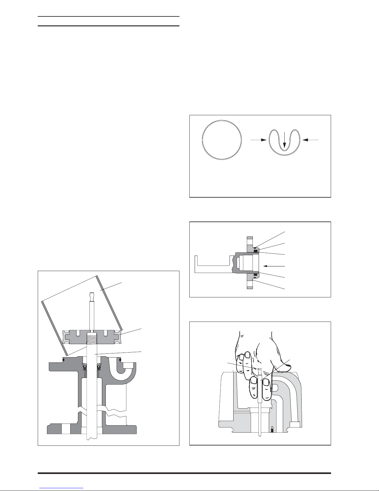
Remove (28) cylinder from (30) base. Usually during this
27.
step, the (24) piston and (48) piston rod will remain in
(28) cylinder.
From (30) base assembly (there are 2 types):
28.
Type 1 (see gure 5, above): Remove (43) snap ring, (44)
washer, (45) “U” cup and (46) washer.
Type 2 (see gure 11, page 8): Remove (49) “O” ring.
43
45
18
30
48
Figure 5
Remove (21) “O” ring from (30) base assembly.
29.
Separate (48) piston rod and (24) piston assembly from
30.
(28) cylinder.
Unscrew (36) extension rod from (27) rod assembly by
31.
holding (27) rod assembly with adjustable type pliers
and placing a wrench on the provided wrench flats at
the top of (36) extension rod.
Unscrew (48) piston rod from (24) piston assembly. Use
32.
provided wrench ats on (48) piston rod. Next, remove
(27) rod assembly from (48) piston rod.
NOTE: Caution should be exercised so as not to mar or
damage the finish on (36) extension rod or (48) piston rod.
6544X-X (en) Page 5 of 8
Page 6
REASSEMBLY OF AIR MOTOR
Apply grease to all “O” rings, “U” cups and other rubber
1.
goods before installing.
Clean the threads on (27) rod assembly and put the
2.
threaded end thru (24) piston assembly.
Hold (27) rod assembly below threads with locking type
3.
pliers. After applying Loctite 271 to the threads, attach
(36) extension rod and draw up tight, using the wrench
ats provided on (36) extension rod. NOTE: Do not mar
or damage the surface of (36) extension rod.
Place the “machined shoulder” end of (27) rod assembly
4.
into the hole in the end of (48) piston rod. After applying Loctite 271 to threads, secure (48) piston rod into
(24) piston assembly and tighten to 50 - 60 ft lbs. (67.8 -
81.3 Nm), using provided wrench ats on (48) piston rod.
NOTE: Do not mar or damage the surface of (48) piston
rod.
Install (21) “O” ring on (30) base assembly.
5.
On type one (30) base assembly (see figure 5, page 5),
6.
install (46) washer, (45) “U” cup (lips up), (44) washer and
(43) snap ring. On type two (30) base assembly (see gure 11, page 8), install (49) “O” ring.
Push (48) piston rod thru (30) base assembly, being care-
7.
ful not to damage the lips of (45) “U” cup or (49) “O” ring.
Grease the inside of (28) cylinder and fill the area be-
8.
tween the lips of (24) piston assembly with grease, then
place (28) cylinder over (24) piston and rod assembly (see
gure 6 below).
Push (24) piston assembly to the top of (28) cylinder.
9.
Install two (18) “O” rings on (29) tube and insert (29) tube
10.
assembly into provided hole of (30) base assembly.
Install (16 and 41) “O” rings on (39) gland.
11.
Grease the bore in (19) head assembly and insert (39)
12.
gland assembly into bore of (19) head assembly with a
twisting motion.
15. Push (36) extension rod thru (41) “O” ring in the base of
(19) head assembly.
16. Press (19) head assembly down, seating against (28) cylinder and (29) tube assembly.
17. Insert four (42) bolts down thru the holes in the ange of
(19) head assembly and (30) base assembly.
18. Screw four (47) nuts on (42) bolts. Alternately and evenly
tighten four (47) nuts.
19. Install (20) “U” cup in (38) adapter, with the lips down toward the thick ange of (38) adapter.
20. Install (35 and 16) “O” rings in the (33) gland.
21. Bend (34) seal in a heart shape (see gure 7 below) and
install in (33) gland, next to (35) “O” ring (see gure 8 below).
Seal free form Seal collapsed form
Push sides in, as shown, then slide into bore and position
seal in groove.
Figure 7
22. Carefully push (31) valve piston into (33) gland to size (34)
seal (see gure 9 below). After sizing, remove (31) valve
piston from (33) gland.
16 - “O” Ring
35 - “O” Ring
34 - Seal
Direction for sizing
28 Cylinder (apply grease
13. Align holes in (39) gland and (19) head assembly and
secure with four (22) screws.
14. Install (21) “O” ring on (19) head assembly.
Page 6 of 8 6544X-X (en)
throughout inside)
Apply grease
48 Piston Rod
Figure 6
31 - Valve Piston
Figure 8
33 - Gland
23. Slide (40) washer over (36) extension rod.
24. Pull (36) extension rod up and grasp with two ngers (see
gure 9 below).
32 Washer
groove
36 Extension Rod
Figure 9
25. Place 90350 special installation tool over (36) extension
rod, with turned diameter down and the chamber side
up.
(continued on page 7)
Page 7
REASSEMBLY OF AIR MOTOR (CONT’D)
26. Fit the turned diameter of the 90350 special installation
tool into the bore in the bottom of (19) head assembly.
27. Place (38) adapter assembly down over (36) extension
rod, with the thread on the (38) adapter up.
28. Insert (32) washer into the groove on the top of (36) extension rod.
29. Pull (38) adapter up around the (32) washer.
30. Place (17) washer over (36) extension rod and onto (38)
adapter.
31. Clean with solvent and put Loctite 271 on the threads of
(38) adapter. Screw (31) valve piston onto (38) adapter
and tighten (see gure 4, page 3).
32. Push the assembled (38) adapter and (31) valve piston
down thru the 90350 special installation tool until it bottoms.
33. Remove the 90350 special installation tool by pulling up
on it.
34. Install (33) gland assembly over the (31) valve piston and
push down, being careful to retain (34) seal in the “O”
ring groove.
35. Align the two screw holes and secure (33) gland assembly to (19) head assembly with two (6) screws and two (7)
lock washers.
36. Insert (13) insert spring assembly into the (19) head
assembly, with the hooks down and the nylon roller toward (31) valve piston.
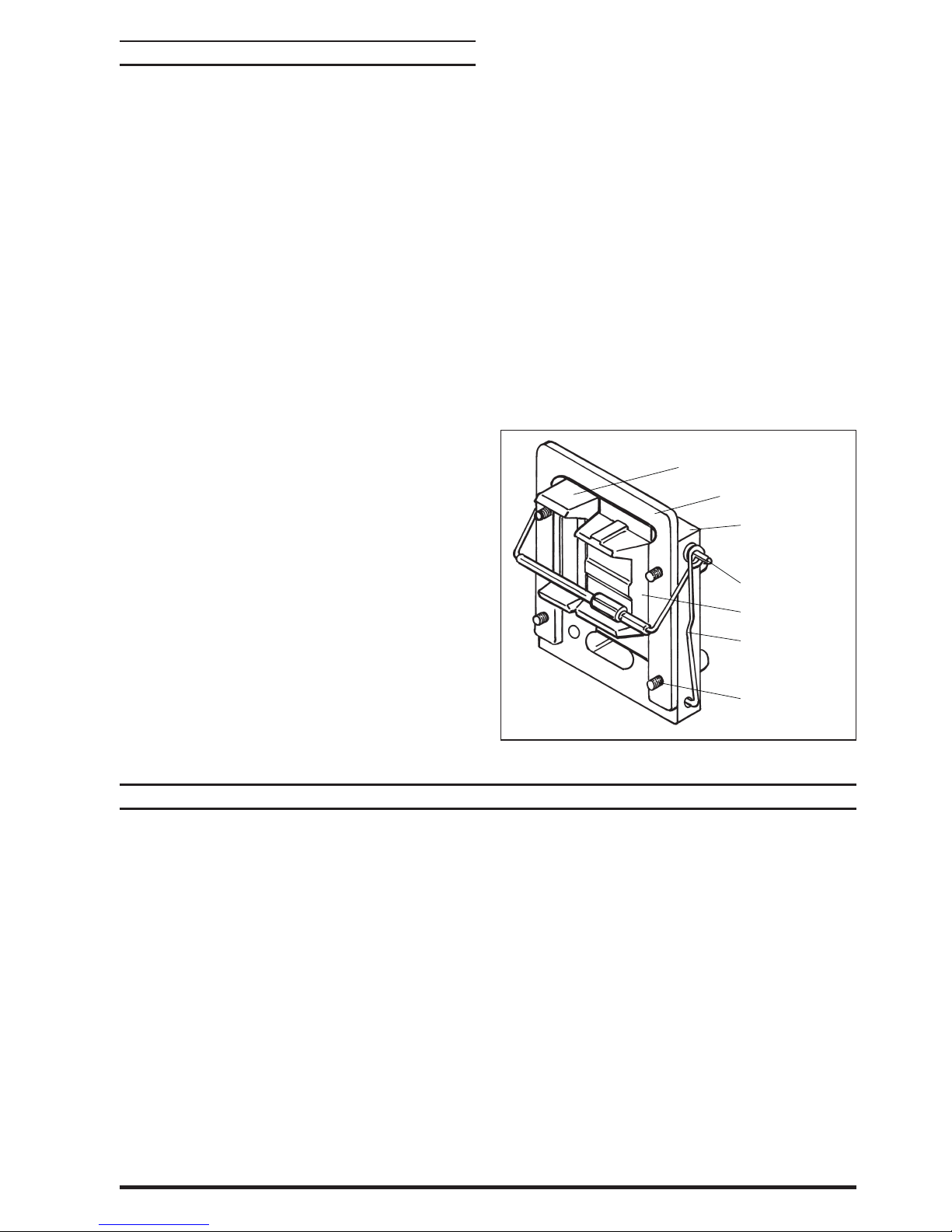
37. Apply grease to both (11 and 14) inserts and place them
in position (see gure 10) with legs of insert toward (31)
valve piston and the larger, (14) insert, located in front of
the larger diameter nylon roller. Also, the nylon roller on
the (13) insert spring assembly should be between the
legs of both (11 and 14) inserts.
38. Apply grease to gasket side of (12) valve plate and put
(15) gasket on (12) valve plate. To determine the correct
side, the screw holes nearest the top and bottom of (12)
valve plate are toward the exhaust port on the (19) head
assembly. Also, the (12a) roll pins in (12) valve plate are
at the top.
39. Hold the (11 and 14) inserts against the (31) valve piston
and slide the (15) gasket and (12) valve plate between
the two inserts and (19) head assembly. Be sure the
larger holes in the (12) valve plate are located in front of
the larger or (14) insert. Also, be sure the pins are located
at the top of the valve plate.
40. Hook the round coil in (13) insert spring assembly over
the (12a) roll pins (see gure 10).
41. Hook the bottoms of the (13) insert spring assembly into
the holes on the side of (12) valve plate (see gure 10).
42. Insert (9) valve guide against the face of (12) valve plate.
The legs of (9) valve guide should be down, with the leg
having the threaded hole nearest the bottom located
nearest the exhaust port of the (19) head assembly.
43. Place (5) washer on each of the four (4) screws and insert
into the provided holes and tighten evenly across the
corners. NOTE: To ease the alignment of the holes, an “O”
ring pick is helpful.
44. Install (10) gasket in (8) air motor cap and secure with six
(3) screws.
45. Place (2) de ector on the exhaust port of (19) head assembly, with the opening down, and secure with four (1)
screws.
11 - Insert
9 - Valve Guide
12 - Valve Plate and
Pin Assembly
12a - Roll Pin
14 - Valve Insert
13 - Insert Spring
Assembly
4 - Screw (4)
5 - Washer (4)
Figure 10
Air leakage out of main exhaust.
Worn (14) insert. Replace (14) insert.
Worn (12) valve plate and pin assembly. Replace (12)
valve plate and pin assembly.
Damaged (24) piston assembly. Replace (24) piston as-
sembly.
6544X-X (en) Page 7 of 8
TROUBLE SHOOTING
Continual air leakage out of bleeder hole in (19) head assembly.
Worn (35) “O” ring or (34) seal. Replace (35) “O” ring and
(34) seal.
Air leakage around (48) piston rod.
Worn (45) “U” cup. Replace (45) “U” cup.
Page 8
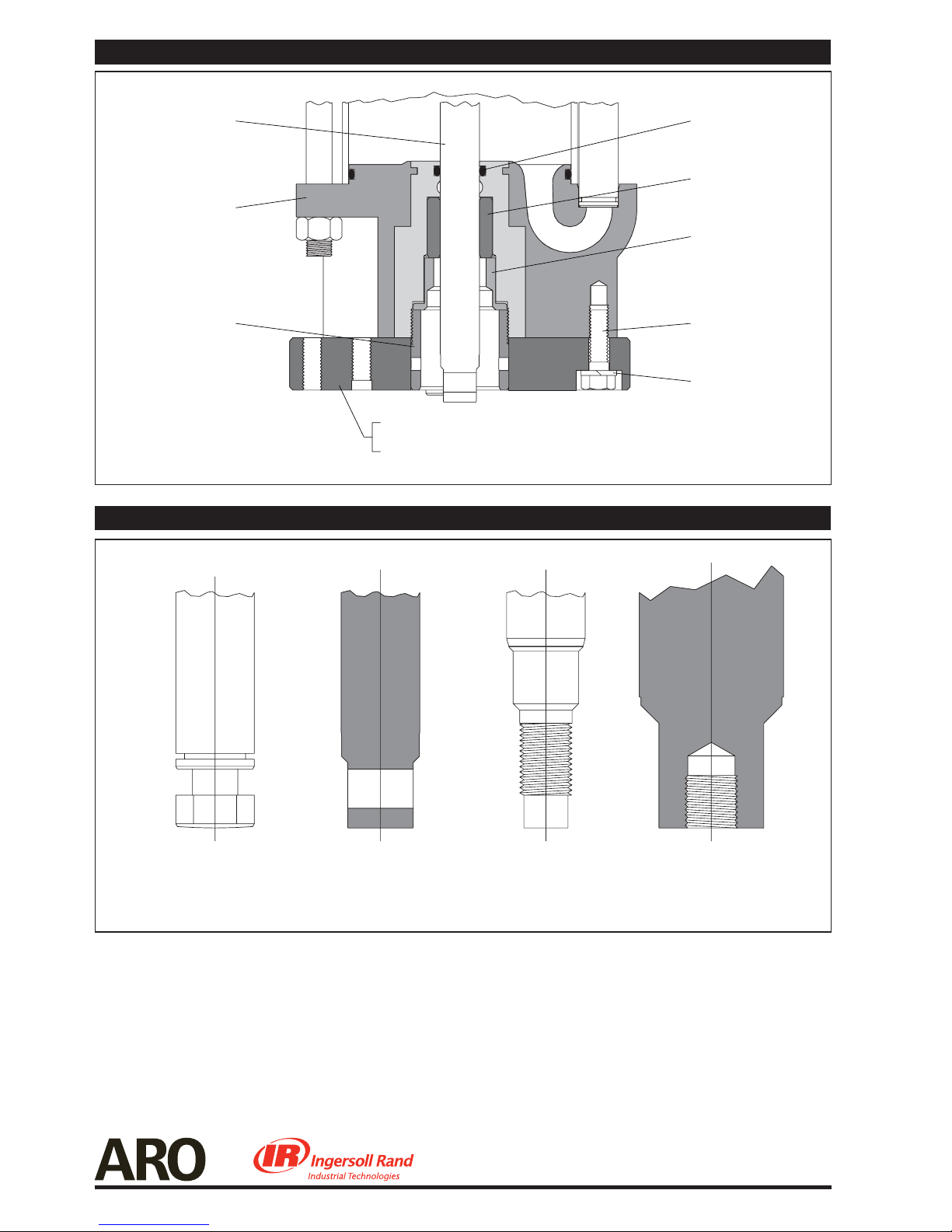
65440 AND 65462 AIR MOTOR PISTON ROD AND BASE
Piston Rod
(see item 48, page 4)
65020 Base and Bearing
Assembly (stub)
93312 Guide
Figure 11
Y325-210 “O” R ing
93310 Bushing
93311 Retainer
Y6-66-C Screw (4 req’d)
Y14-616-C Lock
Washer (4 req’d)
93958 Plate (used on 65440 air motor)
93313 Plate (used on 65462 air motor)
ITEM 48 PISTON ROD END VARIETY
65911-2 Piston Rod
90108-1 Piston Rod
Figure 12
Page 8 of 8 6544X-X (en)
90573 Piston Rod
93964 Piston Rod
61776 Piston Rod
66628 Piston Rod
90595 Piston Rod
90082 Piston Rod
93289 Piston Rod
PN 97999-64
 Loading...