

Page 1
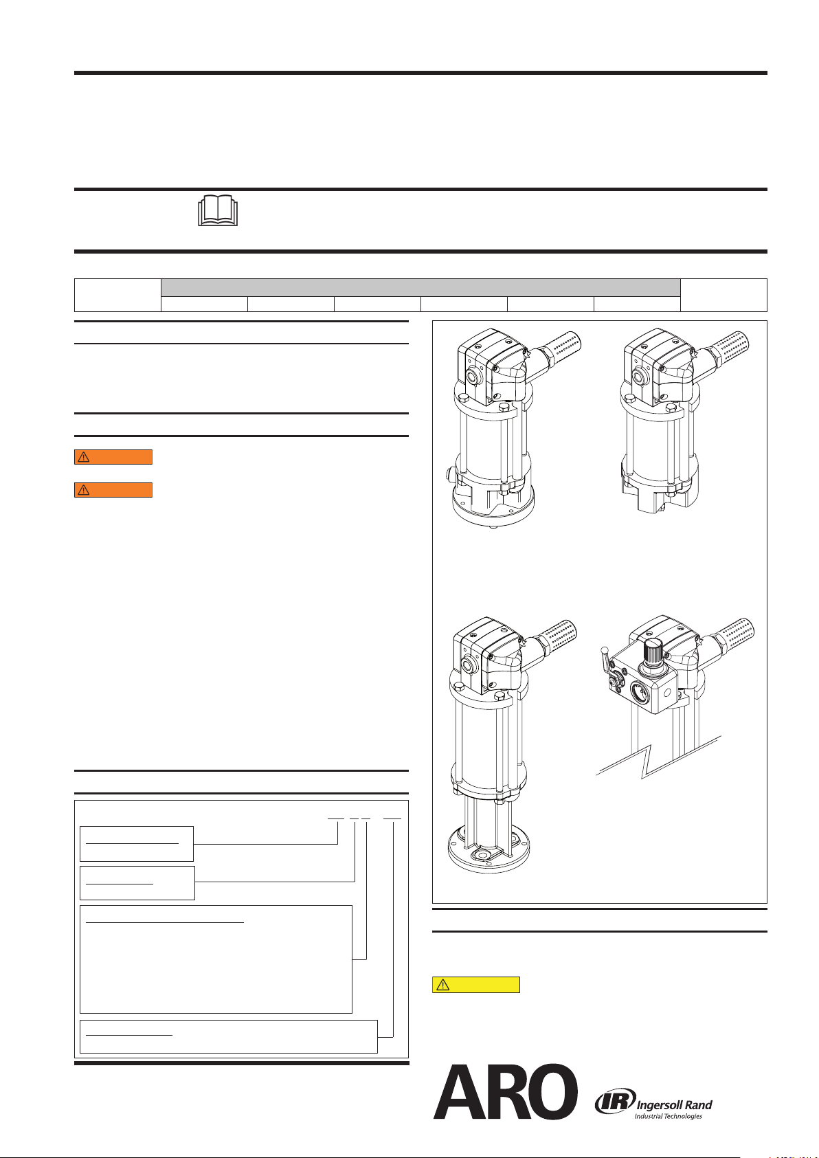
AF044X-XX
WARNING
WARNING
AF0441-XX
AF0442-XX
AF0443-XX
AF0444-XX
AF0445-XX
AF0460-XX
AF04XX-01
CAUTION
OPERATOR’S MANUAL AF046X-XX
INCLUDING: SERVICE KITS, TROUBLESHOOTING, PARTS LIST,
DISASSEMBLY & REASSEMBLY.
RELEASED:
REVISED:
(REV. 02)
4-1/4” AIR MOTORS
AF044X-XX (4” STROKE) and AF046X-XX (6” STROKE)
Also covers 637489 service kits
READ THIS MANUAL CAREFULLY BEFORE INSTALLING,
OPERATING OR SERVICING THIS EQUIPMENT.
It is the responsibility of the employer to place this information in the hands of the operator. Keep for future reference.
THIS MANUAL COVERS THE FOLLOWING MODELS
MODEL
AF0441-XX AF0442-XX AF0443-XX AF0444-XX AF0445-XX AF0460-XX
SERVICE KITS
Use only genuine ARO® replacement parts to assure com-
patible pressure rating and longest service life.
637489 for general repair of all air motors.
GENERAL DESCRIPTION
DO NOT EXCEED MAXIMUM OPERATING
PRESSURE AS INDICATED ON PUMP MODEL PLATE.
REFER TO GENERAL INFORMATION SHEET
FOR ADDITIONAL SAFETY PRECAUTIONS AND IMPORTANT INFORMATION.
This manual only covers the air motor section. It is one of
four documents which support an ARO pump. Replacement copies of these forms are available upon request.
Pump Model Operator’s Manual.
General Information for Air Operated or Hydraulically
Operated Pumps.
Lower Pump End Operator’s Manual.
Air or Hydraulic Motor Operator’s Manual.
The 4-1/4” air motor is a general purpose power unit and
is used with many 2-ball, 4-ball, and chop check pumps.
It utilizes tie rod type construction for easy breakdown
and it connects to the various lower ends via tie rods for
easy operation. Consult pump model operator’s manual
for specic instructions.
8-16-10
8-10-12
MODEL DESCRIPTION CHART
Air Motor Diameter
04 - 4 ¼”
Stroke Length
4 - 4”, 6 - 6”
Air Motor Base/Rod Combination
0 - Divorced pump base with quick coupled rod connection
1 - Divorced pump base with pinned coupled rod connection
2 - Coupled pump base with pinned coupled rod connection
3 - Coupled pump base with male threaded rod connection
4 - Coupled pump base with female threaded rod connection
5 - Coupled high pressure pump base with female threaded
rod connection (See Figure 4)
Air Motor Options
01 – Integrated On/O Valve and Regulator
INGERSOLL RAND COMPANY LTD
209 NORTH MAIN STREET – BRYAN, OHIO 43506
(800) 495-0276 FAX (800) 892-6276
www.ingersollrandproducts.com
A F 04 X X – XX
© 2012 CCN 15330061
Figure 1
OPERATING AND SAFETY PRECAUTIONS
DO NOT EXCEED MAXIMUM AIR INLET PRESSURE OF
150 P.S.I. (10.3 BAR) OR 75 CYCLES PER MINUTE.
High pressure equipment – Always disconnect air supply and relieve material pressure before attempting to service.
A ground lug is located on the air motor. This ground
lug allows proper grounding of the pump.
Page 2
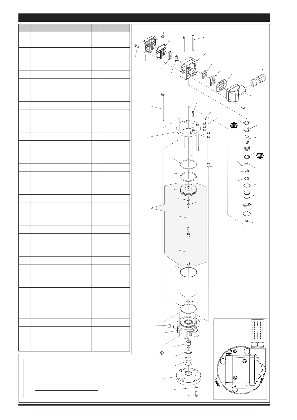
PARTS LIST / AF044X-XX & AF046X-XX
Item Description (Qty) Part No. [Mtl]
111 O-Ring
113
*115 Rod (1) [SS]
116 O-Ring
*117 Piston (1) [A]
*118 O-Ring
*119 Bushing (1) [C]
*120 Trip Rod Assembly (1) [A]
122 Head Plate (1) 96859 [A]
123 O-Ring
124 O-Ring
125 Cap (1) 96897 [D]
126 Sleeve (1) 96901 [Br]
127 Ground Lug (1) 96878 [Bz]
128 O-Ring
129 Snap Ring
130 Washer (1) 96894 [C]
131 Pin (1) 96895 [C]
132 Driver (1) 96868 [C]
133 U-Cup
134 Spool (1) 96875 [A]
135 Vent Bushing (1) 96896 [D]
136 U-Cup
137 Tube (1) 96873 [C]
138 Socket Head Screw
140 Head Manifold (1) 96854 [A]
141 Major Gasket (1) 96900 [B]
142 Valve Plate (1) 96884 [CK]
143 D-Valve (1) 96889 [D]
144 Valve Housing (1) 96864 [A]
145 Socket Head Screw
146 Pilot Insert (1) 96882 [D]
147 Pilot Valve Plate (1) 96883 [CK]
148 Pilot Gasket (1) 96899 [B]
149 Vent Plug (1) 96906 [D]
150 Pilot Cover (1) 96865 [A]
155 Muer (1) 96916 [C]
201 Muer Kit (Optional, See Fig. 5) (1) 67445-1 [C]
202
(1/8” X 4 1/4” o.d.)
(1/16” X 3/4” o.d.)
O-Ring
(3/16” X 4 1/4” o.d.)
(1/16” X 11/16” o.d.)
(3/32” X 1/2” o.d.)
(1/16” X 2” o.d.)
(1/16” X 1 11/16” o.d.)
(1.180” o.d.)
(3/16” X 1 1/2” o.d.)
(5/32” X 1 3/8” o.d.)
(5/16”-18 X 1”)
(5/16”-18 X 4 1/2”)
Regulator / Shut-O (Optional,
See Fig. 5)
Lubriplate FML-2 Grease Packet
(1/4 oz.)
TORQUE REQUIREMENTS
(2) Y325-242 [B]
Y325-16
(4)
(1) Y325-344 [B]
(1) [B]
(1) Y325-109 [B]
(1) Y325-32 [B]
(1) 96917 [B]
(1) Y147-7 [C]
(1) 96908 [B]
(1) 96907 [B]
(8) Y99-52 [C]
(2) Y99-516 [C]
(1) 67442
(2) 94276
[B]
NOTE: DO NOT OVERTIGHTEN FASTENERS.
Tighten (109 & 121) to 10-15 ft-lbs (13.6-20.3 Nm)
Tighten (138 & 145) to 50-60 in-lbs (5.6-6.8 Nm)
LUBRICATION / SEALANTS
NOTE: Lubricate with Grease (ARO p/n 94276).
138
122
*203
Not User
Serviceable
110
Figure 2
150
121
109
147
�
101
106
149
148
146
111
�
116
�
117
112
111
�
103
104
105
107
�
119
120
115
�
108
127
118
102
�
145
144
�
143
113
142
�
�
137
114
113
�
TORQUE SEQUENCE
2
141
�
136
131
130
129
4
�
155
140
138
135
134
133
�
132
128
�
126
125
�
124
123
�
3
1
Page 2 of 8 AF044X-XX & AF046X-XX (en)
Page 3
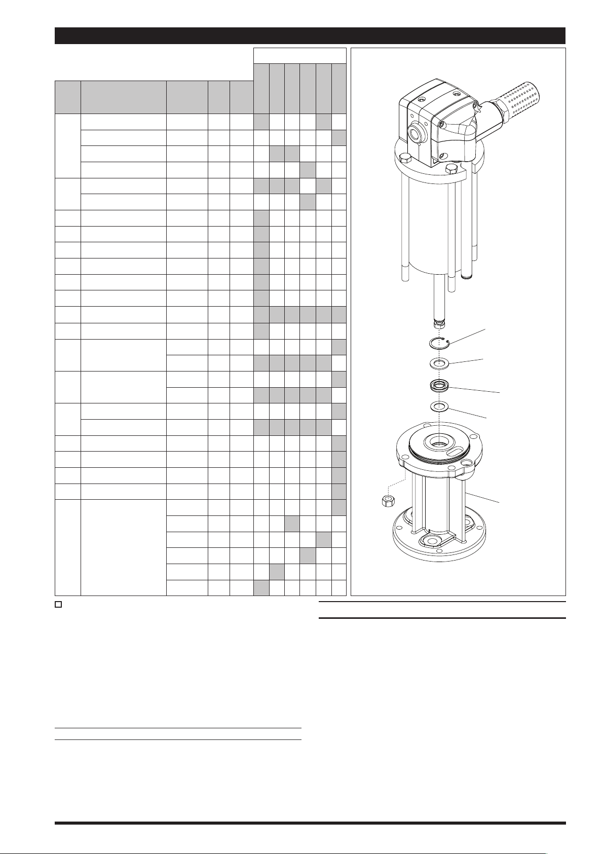
PARTS LIST / AF044X-XX & AF046X-XX
101
151
152
153
154
�
AIR MOTOR MODEL NO.
Item Description
Base & Bearing
Base & Bearing 65023 (1) [A]
101
Base & Bearing
Base
O-Ring
102
O-Ring
Bushing 93310 (1) [D]
103
Retainer 93311 (1) [SS]
104
Guide 93312 (1) [SS]
105
Plate 93958 (1) [A]
106
107 Lock Washer Y14-616-C (4) [C]
Screw
108
Nut
109
Plug
110
Cylinder
112
Tube
114
Bolt
121
Bolt
Washer 90103 (1) [A]
151
U-Cup
152
Washer 73986 (1) [Br]
153
Snap Ring
154
Piston Assembly
(includes items 115, 117, 118,
*203
119, & 120)
Indicates where parts are used.
Items included in Service Kit (637489).
(size)
(Stub)
(Stub)
(Stub)
(1/8” x 1” O.D.)
(1/8” x 1 5/8” O.D.)
(1/2” - 20)
(1/2-14 N.P.T. X 9/16”)
(1/2” - 20 x 10 1/4”)
(1/2” - 20 x 8 1/4”)
(1/4” X 1 1/4” O.D.)
(1.456” O.D.)
Part No. (Qty) [Mtl]
** 65020 (1) [A]
65775 (1) [A]
90074 (1) [A]
[B]
Y325-210
Y325-220 (1) [B]
Y6-66-C
Y11-8-C (4) [C]
93897-1 (1) [PP]
96936 (1) [Ef]
96935 (1) [Ef]
96874-1 (1) [C]
96874-2 (1) [C]
94046-1 (4) [C]
94046-2 (4) [C]
Y186-16 (1) [B]
Y147-131 (1) [C]
67489 (1) --
67490 (1) --
67491 (1) --
67492 (1) --
67493 (1) --
67494 (1) --
(1)
(4)
[C]
AF0441-XX
AF0442-XX
AF0443-XX
NOTE: Base styles and lower packings may vary from that
shown on the cover. Refer to model number in the chart
above.
For simplication of ordering and stocking, the Universal Service Kit contains service parts that can be used for every size
of air motor. When repairing the motor, use only the parts that
are needed for that specic motor. Extra service parts from the
kit will remain after repair of the air motor.
[A] = Aluminum [D] = Acetal
[B] = Buna Nitrile [PP] = Polypropylene
[Br] = Brass [SS] = Stainless Steel
[Bz] = Bronze [Ef] = Epoxy - Fiberglass Filament Reinforced
[C] = Carbon Steel
[CK] = Ceramic
MATERIAL CODE
AF0444-XX
AF0445-XX
AF0460-XX
DISASSEMBLY OF AIR MOTOR
NOTE: All threads are right hand.
Force the piston assembly up by pushing the (115) rod
1.
toward the top of the air motor.
Remove the (155) muffler/(201) muffler assembly for
2.
ease of disassembly.
Remove four (138) socket head screws from the (140)
3.
head manifold. Remove the (140) head manifold by
pulling up and outward to remove from tubes (114) and
(137).
Remove (141) major gasket from the (140) head mani-
4.
fold.
Remove tubes (114) and (137) by pulling upward.
5.
Remove the four (113) O-rings from both tubes (114) and
6.
(137).
Figure 3
(continued on page 4)
AF044X-XX & AF046X-XX (en) Page 3 of 8
Page 4

DISASSEMBLY OF AIR MOTOR (CONT’D)
Remove the (142) valve plate and the (143) D-valve from
7.
the (144) valve housing.
Remove the four (138) socket head screws to extract the
8.
(150) pilot cover.
Remove the (148) pilot gasket from the (150) pilot cover.
9.
Remove the (147) pilot valve plate and the (146) pilot
10.
insert from the (144) valve housing.
Remove the two (145) socket head screws from the (144)
11.
valve housing.
Remove the (144) valve housing by pulling straight up.
12.
Remove the (124) O-ring, the (135) vent bushing, and the
13.
(136) U-cup from the (144) valve housing.
Remove the (128) O-ring and the (126) sleeve from the
14.
motor assembly by sliding it straight up.
Pull the (134) spool as far from the motor assembly as
15.
possible to expose the under side of the spool itself.
Locate and remove the (129) snap ring from the (134)
16.
spool utilizing snap ring pliers.
Lift to remove the (134) spool and remove the (133)
17.
U-cup from it.
Slide the (131) pin to remove the (132) driver, (130)
18.
washer, and (129) snap ring from the (120) trip rod assembly.
Remove the four (109) nuts from (121) hex head bolts.
19.
Remove the four (121) bolts from the (122) head plate
20.
and the (101) base assembly.
Remove (122) head plate from the (112) air cylinder.
21.
Remove the (111) O-ring, the (125) cap, and (123) O-ring
22.
from the (122) head plate.
Pull upward on (112) air cylinder until (203) piston as-
23.
sembly separates from the (101) base assembly. If, in this
step, the (203) piston assembly is not pulled from the
(101) base assembly, then remove it after removing the
(112) air cylinder.
If the (112) air cylinder and (203) piston assembly are
24.
removed as one unit, then remove the (203) piston assembly from the (112) air cylinder.
Remove the (116) O-ring from the (117) piston.
25.
Remove the (111) O-ring from (101) base assembly.
26.
For model AF0460-XX, remove (154) snap ring, (153)
27.
washer, (152) U-cup, and (151) washer from the (101)
base assembly. For all other models remove the (102)
O-ring from the (101) base assembly.
REASSEMBLY OF AIR MOTOR
Apply grease to all O-rings, U-cups, and other rubber
1.
goods before installing.
For model AF0460-XX, install (151) washer, (152) U-cup,
2.
(153) washer, and (154) snap ring into the (101) base assembly. For all other models, install the (102) O-ring into
the (101) base assembly.
Install the (111) O-ring in the groove on the (101) base
3.
assembly.
Install the (116) O-ring in the groove on the (117) piston.
4.
Push (115) piston rod thru the (101) base assembly, be-
5.
ing careful not to damage the lips of the (152) U-cup or
the (102) O-ring.
Lubricate the inside diameter of the (112) air cylinder
6.
and slide it down over the (203) piston assembly and
onto the (101) air motor base assembly. (See Figure 2 on
page 2).
Align notch in (122) head plate with the port in (101) base
7.
assembly and press the (122) head plate down until it is
seated against the (112) air cylinder. The (120) trip rod assembly must lead thru the center of the (122) head plate.
Assemble the four (121) bolts thru the (122) head plate
8.
and the (101) base assembly.
Assemble the four (109) nuts to (121) hex head bolts and
9.
tighten per specied torque sequence and value.
Pull the (120) trip rod assembly as far out of the air mo-
10.
tor assembly as possible, slide the (123) O-ring over the
(120) trip rod assembly and down into the gland found
in the (122) head plate.
Slide the (125) cap over the (120) trip rod assembly and
11.
down into the bore found in the (122) head plate.
Slide the (129) snap ring rst and the (130) washer sec-
12.
ondly, onto the (120) trip rod assembly.
Slide the (132) driver onto the (120) trip rod assembly.
13.
Align the hole of the (132) driver with the hole in the
(120) trip rod assembly and insert the (131) pin.
Assemble the (133) U-cup to the (134) spool. Take note
14.
of the (133) U-cup lips should point down towards the
(122) head plate.
Slide the (134) spool onto the (120) trip rod assembly over
15.
the (132) driver and insert the (130) washer behind it. Utilizing snap ring pliers, assemble the (129) snap ring to the
internal groove found in the (134) spool. Be certain that
the (129) snap ring is fully engaged into the groove. Slide
the (134) spool downward into the bore of the (122) head
plate nesting on top of the (125) cap.
Lubricate the inside diameter of the (126) sleeve and
16.
slide it onto the (134) spool and locating it into the (125)
cap. Take note that large taper on (126) Sleeve is to locate into (125) Cap.
Install the (128) O-ring onto the top gland of the (126)
17.
sleeve.
Install the (136) U-cup, the (135) vent bushing into the
18.
center bottom bore of the (144) valve housing. Take
note that the (136) U-cup lips must be facing up towards
the top of the (144) valve housing. Install the (124)
O-ring into the bottom recess gland of the (144) valve
housing.
Install the (144) valve housing to the motor assembly
19.
by sliding the center bore onto the (134) spool and the
(126) sleeve. Take caution not to dislodge any of the
O-rings (124 & 128). Take note to align the large valve
pocket on the side of the (144) valve housing towards
the notch in the (122) head plate.
Install the two (145) socket head screws thru the (144)
20.
valve housing and thread into the (122) head plate. The
(144) valve housing may need to be rotated slightly to
align the tapped holes. Tighten the (145) socket head
screws per specied torque value.
Install the (146) pilot insert, with pocket facing outward,
21.
thru the (144) valve housing and into the (134) spool. The
(134) spool may need to be turned to orient its’ shallower
slot to face the smaller pocket of the (144) valve housing.
Install the (147) pilot valve plate, with identification
22.
dimple facing outward, into the (144) valve housing covering the (146) pilot insert.
Install the (148) pilot gasket into the (150) pilot cover
23.
and assemble to the (144) valve block using four (138)
socket head screws. Tighten to torque specications.
Install the (143) D-valve, with pocket facing outward,
24.
thru the (144) valve housing and into the (134) spool.
(continued on page 5)
Page 4 of 8 AF044X-XX & AF046X-XX (en)
Page 5
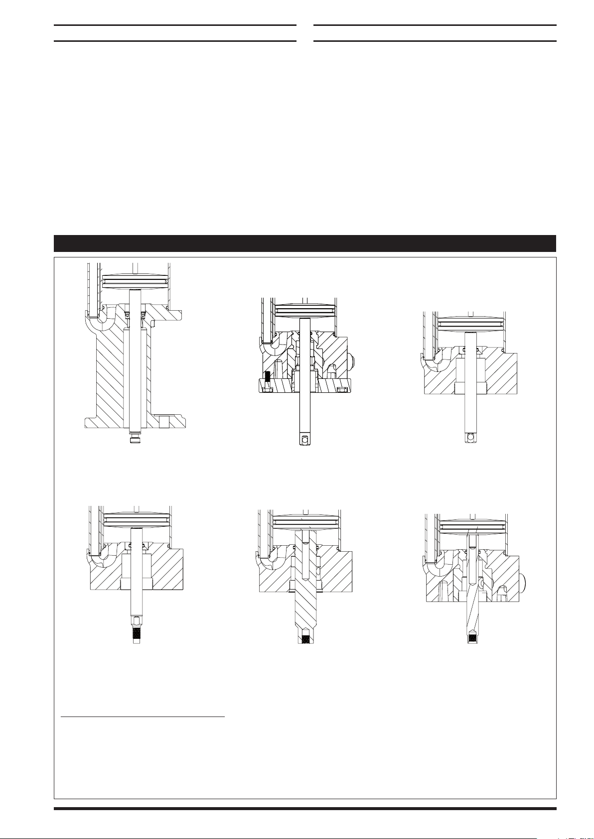
REASSEMBLY OF AIR MOTOR (CONT’D)
TYPE -0-
Divorced Base, Quick Coupled Rod
65023 BASE and
67489 PISTON ASSEMBLY
TYPE -1-
Divorced Base, Pin Coupled Rod
65020 BASE with 93958 INSERT and
67494 PISTON ASSEMBLY
TYPE -2-
Coupled Base, Pin Coupled Rod
65775 BASE and
67493 PISTON ASSEMBLY
TYPE -3-
Coupled Base, Male Threaded Rod
65775 BASE and
67490 PISTON ASSEMBLY
TYPE -4-
Coupled Base, Female Threaded Rod
90074 BASE and
67492 PISTON ASSEMBLY
TYPE -5-
Coupled High Pressure Base,
Female Threaded Rod
65020 BASE and
67491 PISTON ASSEMBLY
Air Motor Base and Rod Combination
0 – Divorced pump base with quick coupled rod connection
1 – Divorced pump base with pin coupled rod connection
2 – Coupled pump base with pin coupled rod connection
3 – Coupled pump base with male threaded rod connection
4 – Coupled pump base with female threaded rod connection
5 – Coupled high pressure pump base with female threaded rod connection
Install the (142) major valve plate, with identification
25.
dimple facing outward, into the (144) valve housing covering the (143) D-valve.
Install the four (113) O-rings onto both (114 & 137) tubes.
26.
Loosely install the (137) tube into the bore in the (122)
27.
head plate.
Loosely install the (114) tube into the bore in the (101)
28.
base assembly.
Install the (141) manifold gasket into the (140) mani-
29.
fold and telescope onto both (114 & 137) tubes until
the (113) O-rings are seated. Fasten the (140) manifold
to the (144) valve block using four (138) socket head
screws. Tighten to torque specications.
Install the (155) muer/(201) muer assembly.
30.
VARIETIES OF BASE (101) AND PISTON ROD END (115)
TROUBLE SHOOTING
Air leakage out of main exhaust.
Damaged (141) track gasket. Replace (141) track gasket.
Worn (116) piston seal. Replace (116) piston seal.
Continual air leakage out (149) pilot exhaust.
Worn (136) “U” cup. Damaged (148) track gasket. Replace
(136) “U” cup and (148) track gasket.
Air leakage out (149) pilot exhaust only during the down
stroke.
Worn (133) “U” cup. Rolled or damaged (128) “O” ring. Re-
place (133) “U” cup and (128) “O” ring.
Air leakage around (115) piston rod.
Worn or damaged (102) “O” ring or (152) “U” cup depend-
ing on motor model. Replace (102) “O” ring or (152) “U”
cup depending on motor model.
AF044X-XX & AF046X-XX (en) Page 5 of 8
Figure 4
Page 6
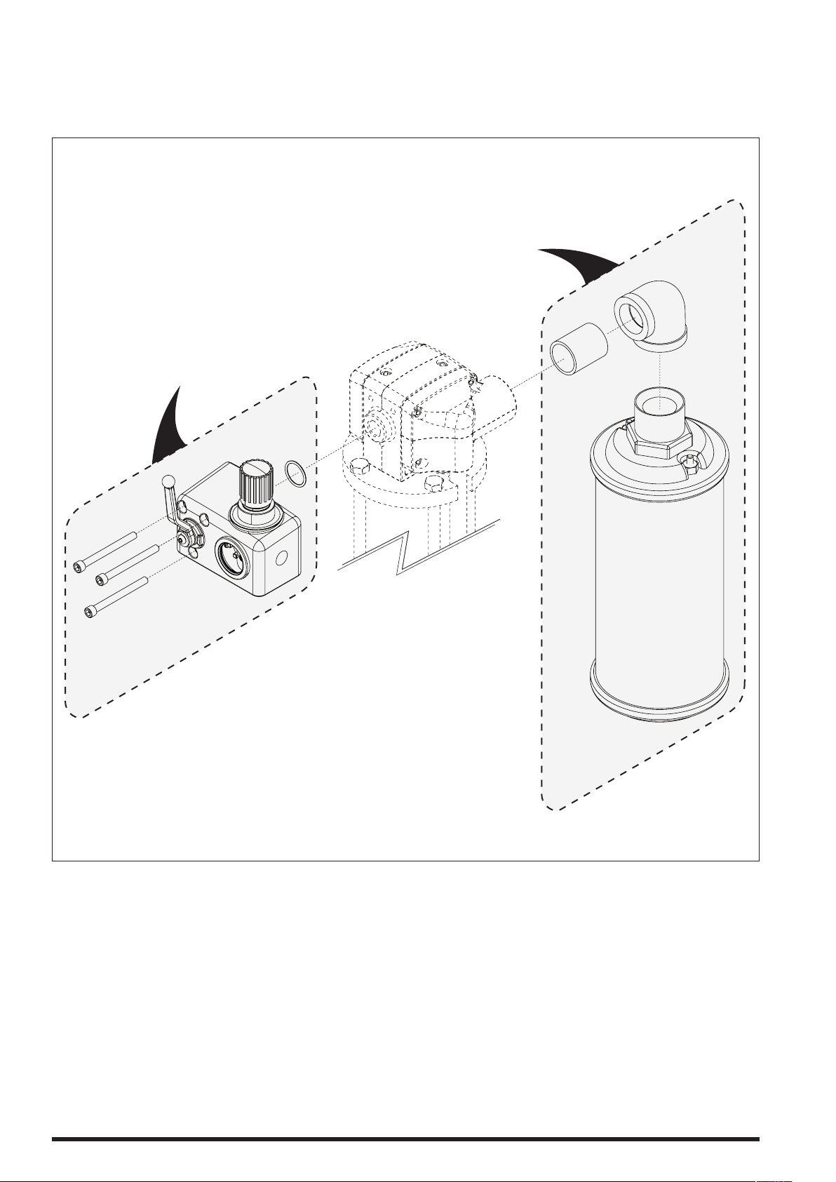
Available Options for AF04XX-XX Air Motors
201
Optional
67445-1
Muer Kit
202
Optional
67442
Self-Relieving
Ball Valve
Regulator / Shut-O
(AF04XX-01)
Figure 5
Page 6 of 8 AF044X-XX & AF046X-XX (en)
Page 7

NOTES
AF044X-XX & AF046X-XX (en) Page 7 of 8
Page 8

PN 97999-1466
Page 8 of 8 AF044X-XX & AF046X-XX (en)
 Loading...