

Page 1
OPERATOR’S MANUAL & SALES AND ENGINEERING DATA
“B”
“A”
“C”
INCLUDING: SPECIFICATIONS, SERVICE KITS, GENERAL INFORMATION, TROUBLESHOOTING.
INCLUDE MANUALS: AF066X-XX Air Motor (pn 97999-1467), 66243-XXX-B Lower Pump End (pn 97999-828)
& S-632 General Information Manual (pn 97999-624).
6” AIR MOTOR
23:1 RATIO
6” STROKE
AF0623SXXXXXX-XX-X
EXTRUSION PUMP SERIES
Carbon Steel
READ THIS MANUAL CAREFULLY BEFORE INSTALLING,
OPERATING OR SERVICING THIS EQUIPMENT.
It is the responsibility of the employer to place this information in the hands of the operator. Keep for future reference.
RELEASED: 9-30-10
(REV. 01)
SERVICE KITS
Use only genuine ARO® replacement parts to assure compat-
ible pressure rating and longest service life.
637489 for repair of air motor section.
637071-XX3-B for repair of lower pump end. Refer to the chart
on page 2 for description of -XX3 options.
SPECIFICATIONS
Model Series
Pump Type . . . . . . . . . . . . . . . . . . . . . . . . . . . . . . . Air Operated, Extrusion
Double Acting Pump
Ratio . . . . . . . . . . . . . . . . . . . . . . . . . . . . . . . . . . . . . 23:1
Air Motor . . . . . . . . . . . . . . . . . . . . . . . . . . . . . . . . AF0660-XX
Motor Repair Kit . . . . . . . . . . . . . . . . . . . . . . . 637489
Motor Diameter . . . . . . . . . . . . . . . . . . . . . . . 6” (15.2 cm)
Stroke (double acting) . . . . . . . . . . . . . . . . . 6” (15.2 cm)
Air Inlet (female) . . . . . . . . . . . . . . . . . . . . . . . 1/2 - 14 N.P.T.F. - 1
Air Exhaust (female). . . . . . . . . . . . . . . . . . . . 1-1/4 - 11-1/2 N.P.T.F. - 1
Lower Pump End Series . . . . . . . . . . . . . . . . . . 66243-XX3-B
Lower Pump Repair Kit . . . . . . . . . . . . . . . . 637071-XX3-B
Material Outlet (female) . . . . . . . . . . . . . . . 1 - 11-1/2 N.P.T.F. - 1
Weight . . . . . . . . . . . . . . . . . . . . . . . . . . . . . . . . . . . 67.3 lbs (30.5 kgs)
Air Inlet Pressure Range . . . . . . . . . . 0 - 150 p.s.i.g. (0 - 10.3 bar)
Fluid Pressure Range . . . . . . . . . . . . . . . 0 - 4215 p.s.i.g. (0 - 290.7 bar)
Maximum Rec'd Cycles / Minute . . . . . . . . . 60
Displacement In.³ Per Cycle. . . . . . . . . . . . . . . . 12.5
Volume / Cycle . . . . . . . . . . . . . . . . . . . . . . . . . . . 6.9 oz. (204.6 ml)
Cycles Per Gallon . . . . . . . . . . . . . . . . . . . . . . . . 18.5
Flow @ 60 Cycles / Minute . . . . . . . . . . . . . . . . 3.2 g.p.m. (12.3 l.p.m.)
Noise Level @ 60 p.s.i. - 40 c.p.m. . . . . . . . . 84.7 db(A)
The pump sound pressure level has been updated to an Equivalent Continuous
Sound Level (LAeq) to meet the intent of ANSI S1.13-1971, CAGI-PNEUROP S5.1
using four microphone locations.
(refer to option chart)
. . . . . . . . . . . AF0623SXXXXXX-XX-X
PUMP PERFORMANCE
PUMP DATA
MODEL AF0623SXXXXXX-XX-X
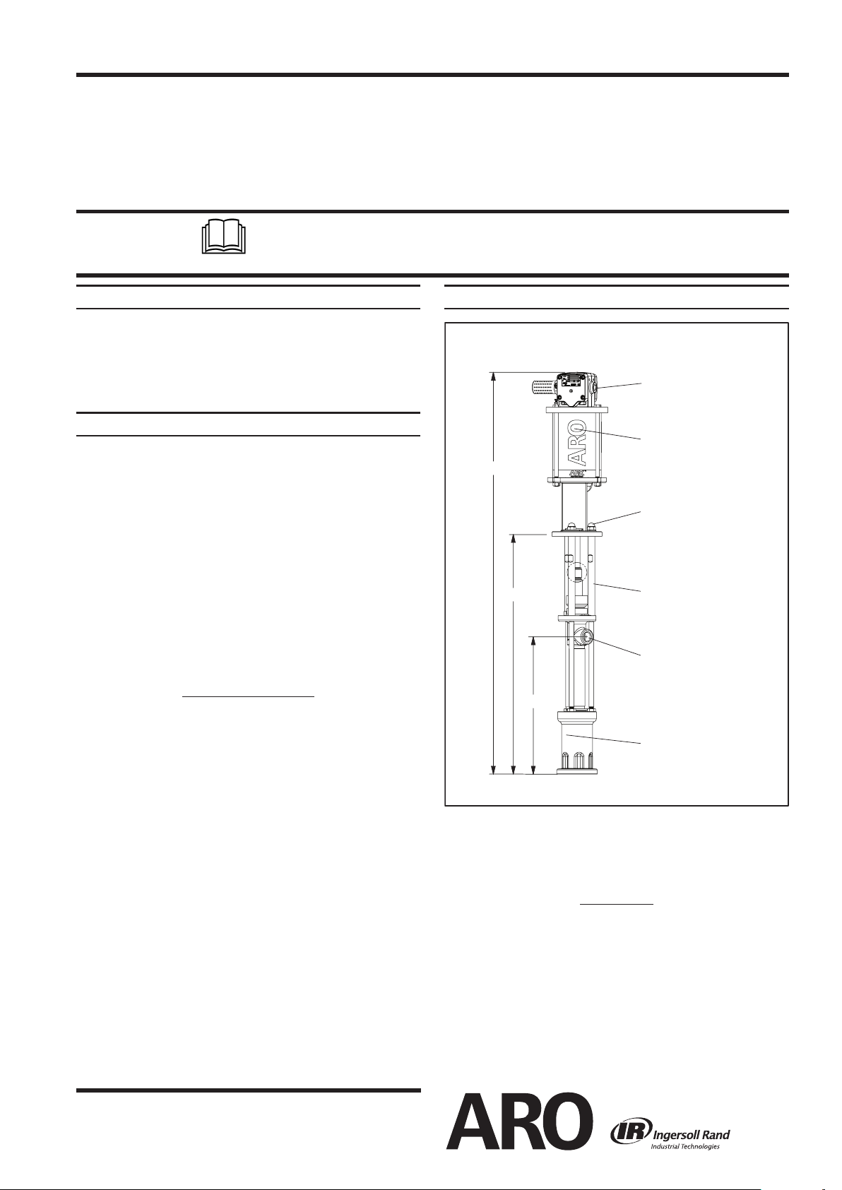
Air Inlet (female)
1/2 - 14 N.P.T.F. - 1
AF0660-XX Air Motor
(see manual AF066X-XX)
Y85-29-C Nut (3)
Spacer Section
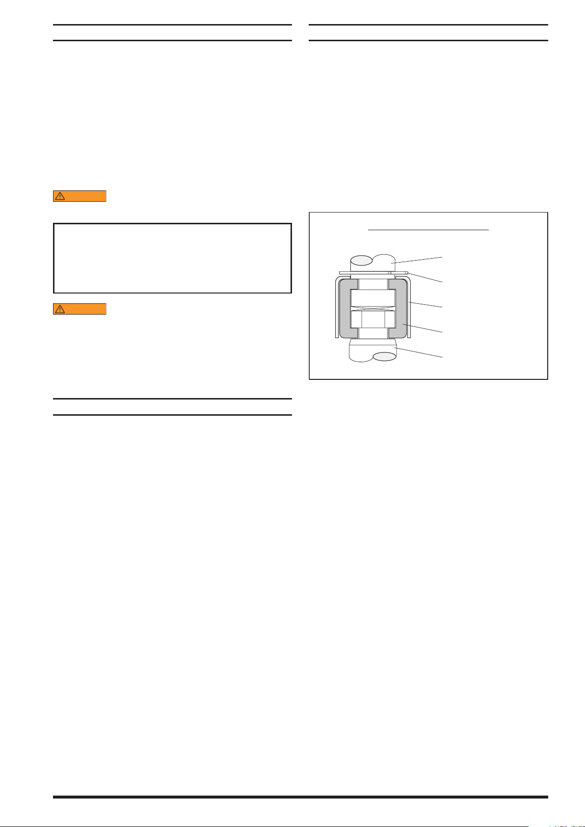
Connector (see gure 2)
92028 Spacer Rod (3)
Material Outlet (female)
1 - 11-1/2 N.P.T.F. - 1
66243-XX3-B Lower Pump
(see manual 66243-XXX-B)
NOTE: Dimensions are shown in inches and (mm) and are supplied for reference only.
(mm)
“A”
“B”
(1318.8)
51.924”
(for -1 model)
(1371.8)
54.009”
30.736"
30.736"
(mm)
“C”
(780.6)
(780.6)
(mm)
17.736"
17.736"
(450.4)
(450.4)
Figure 1
INGERSOLL RAND COMPANY LTD
209 NORTH MAIN STREET – BRYAN, OHIO 43506
(800) 495-0276 FAX (800) 892-6276
www.ingersollrandproducts.com
© 2010 CCN 15333958
IMPORTANT
This is one of four documents which support the pump. Replacement copies of these forms are available upon request.
AF06 23SXXXXXX-XX-X Model Oper a tor’s Manual (pn
97999-1506)
S-632 General Information - Industrial Piston Pumps (pn
97999-624)
66243-XXX-B Lower Pump End Operator’s Manual (pn 97999-828)
AF066X-XX Air Motor Operator’s Manual (pn 97999-1467)
Page 2
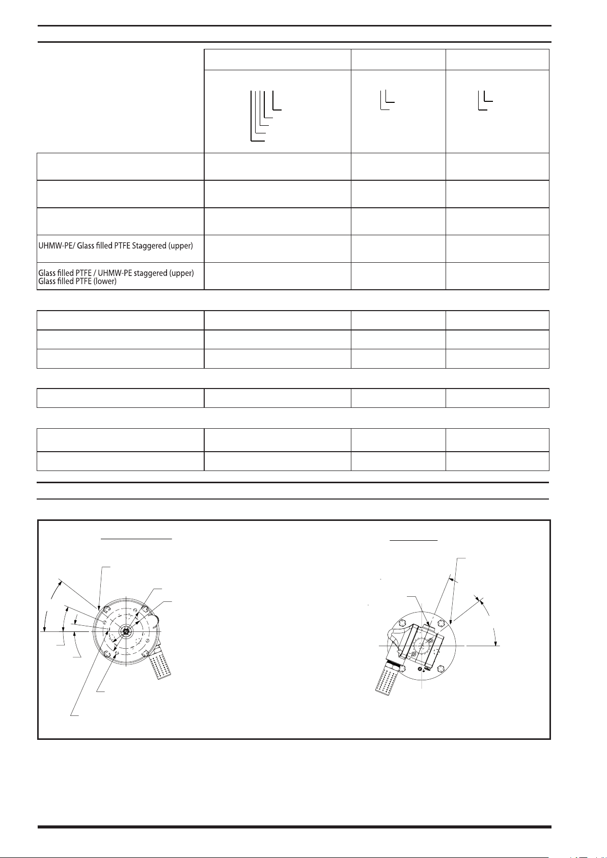
Packing Material:
AF0623S11
X
X
X
X
-
X
Plunger Type
Spring Type
Lower Packing Material
Upper Packing Material
Air Motor Option
67243
-
XX3-B
Packing Material
Spring Type
637071
-
X
X3-B
Packing Material
Spring Type
TOP VIEW
BOTTOM VIEW
5.625 (142.875 mm) dia.
4.125 (104.775 mm) dia.
38°
23°
8°
C
L
Material outlet
0.406 (10.3 mm)
dia. thru 4 equally spaced
0.406 (10.3 mm)
dia. thru 6 equally spaced
30°
38°
Air Inlet
1/2 - 14 N.P.T.F. -1
C
L
Material outlet
PUMP OPTION DESCRIPTION CHART
Pump Model Lower Pump End Lower End Repair Kit
Glass Filled PTFE (upper)
Glass Filled PTFE (lower)
UHMW-PE (upper)
UHMW-PE (lower)
UHMW-PE/ Leather Staggered (upper)
UHMW-PE/ Leather Staggered (lower)
UHMW-PE (lower)
KK 3 3
FF C C
HH G G
GF P P
RK R R
Spring Type
Multiple Wave Spring 4 4 4
Multiple Wave Spring with alternate solvent cup D 9 4
Multiple Wave Spring with two-piece spacer 8 B B
Plunger Type
Hardened Stainless Steel w/ hard chrome coating 7 3 3
Air Motor Option
No Option N/A N/A
Intergrated ball valve regulator 1 N/A N/A
DIMENSIONS
Page 2 of 4 AF0623SXXXXXX-XX-X (en)
Page 3
GENERAL DESCRIPTION
WARNING
WARNING
PUMP CONNECTION DETAIL
90163-8 Extension Rod
90102 Retaining Ring (2)
Lower Pump Piston Rod
90096 Connector (4)
90109 Sleeve (2)
Figure 2
PUMP CONNECTION - UPPER / LOWER
The chop-check pumps are primarily designed for the pumping of
heavy viscous material with or without brous content. The models
can be used with a gravity feed single post lift as a topper type
assembly or with a two post lift as a force feed type assembly. The
lower pump is designed for easy priming and the double acting
feature is standard in all ARO industrial pumps. Material is delivered
to the pump discharge outlet on both the up and down stroke.
The motor is connected to the lower pump end by a spacer section.
This allows for lubrication of the upper packing gland and prevents
motor contamination because of normal wear and eventual leakage through the material packing gland. Be sure the solvent cup is
adequately lled with lubricant to protect the upper packings and
insure longest service life.
HAZARDOUS PRESSURE. Do not exceed maximum operating pressure of 4215 p.s.i. (290.7 bar) at 150
p.s.i. (10.3 bar) inlet air pressure.
Pump Ratio X = Maximum Pump
Inlet Pressure to Pump Motor Fluid Pressure
Pump ratio is an expression of the relationship between the pump motor area
and the lower pump end area. EXAMPLE: When 150 p.s.i. (10.3 bar) inlet pressure
is supplied to the motor of a 4:1 ratio pump, it will develop a maximum of 600
p.s.i. (41.4 bar) uid pressure (at no ow) - as the uid control is opened, the ow
rate will increase as the motor cycle rate increases to keep up with the demand.
Refer to general information sheet for additional
safety precautions and important information.
NOTICE: Thermal expansion can occur when the uid in the material lines is exposed to elevated temperatures. Example: Material
lines located in a non-insulated roof area can warm due to sunlight.
Install a pressure relief valve in the pumping system.
Replacement warning label (pn 92325) is available upon request.
TROUBLE SHOOTING
Pump problems can occur in either the air motor section or the
lower pump end section. Use these basic guidelines to help determine which section is aected.
Pump will not cycle.
Be certain to first check for non-pump problems including
kinked, restrictive or plugged inlet / outlet hose or dispensing
device. Depressurize the pump system and clean out any obstructions in the inlet / outlet material lines.
Refer to the motor manual for trouble shooting if the pump
does not cycle and / or air leaks from the air motor.
Damaged motor. Service the motor.
NOTE: All threads are right hand.
Lay the pump assembly on a work bench.
1.
Remove the three (Y85-29-C) nuts from the three spacer rods
2.
(see gure 1).
Pull the air motor from the lower pump end until the motor
3.
piston rod is in the “down” position and the lower pump end
rod is in the “up” position.
Using e-ring pliers, slide the retaining ring up far enough to
4.
allow the sleeve to move upward and release the two connectors (see gure 2). Lay the air motor aside.
Repeat step 4 to remove the other connector, then remove the
5.
extension rod.
Unscrew the three (92028) spacer rods only if disassembly of
6.
the lower pump end is necessary.
REASSEMBLY
Align the pump motor and extension rod with the lower pump
1.
end. Position the air inlet of the motor 30° from the material
outlet.
Install the two (90096) connectors and retain with the (90109)
2.
sleeve. Slide the (90102) retaining ring back into position.
Assemble the three (92028) spacer rods to the lower pump
3.
end and torque evenly to 60 - 90 ft lbs (81.3 - 122.0 Nm).
Bring the motor and lower pump together and retain with
4.
three (Y85-29-C) nuts.
Pump cycles but does not deliver material.
Refer to the lower pump end manual for further trouble shoot-
ing.
AF0623SXXXXXX-XX-X (en) Page 3 of 4
Page 4
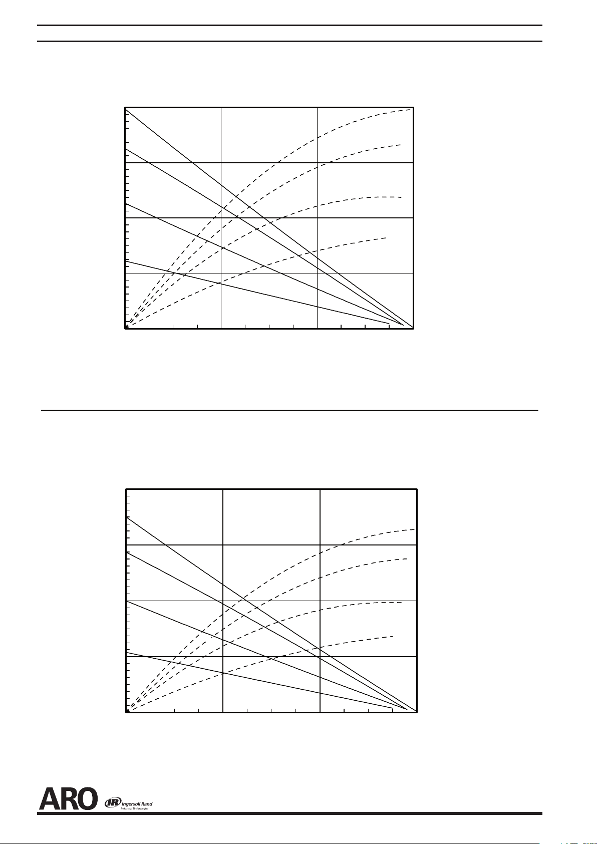
PERFORMANCE CURVES
0 4 8 12
0
800
1600
2400
3200
BACKPRESSURE (PSI)
0
50
100
150
200
250
300
AIR CONSUMPTION (SCFM)
0 83.3 166.6 250
0 83.3 166.6 250
40 PSI
70 PSI
100 PSI
120 PSI
U.S. GALLONS PER MINUTE WATER DELIVER
CYCLE PER MINUTE
BACKPRESSURE (Bar)
AIR CONSUMPTION (Liters/ Sec.)
CYCLE PER MINUTE
2.7 bar
4.8 bar
6.8 bar
8.3 bar
2.7 bar
4.8 bar
6.8 bar
8.3 bar
LITERS PER MINUTE WATER DELIVER
40 PSI
70 PSI
100 PSI
120 PSI
0.00
62.50
125.00
187.50
250.00
0.00
4.17
8.33
12.50
16.67
20.83
25.00
0
16
32 48
Page 4 of 4 AF0623SXXXXXX-XX-X (en)
PN 97999-1506
 Loading...