

Ingersoll-Rand 7/26E, 7/31E, 7/41, 7/51 Operation And Maintenance Manual
SERIAL No :
SERIAL No :
7/26E, 7/31E, 7/41, 7/51
OPERATION AND MAINTENANCE MANUAL
Original Instruction
This manual contains
important safety information
and must be made available to
personnel who operate and
maintain this machine.
4420007/51 −>
7/41
−>
3180007/31E −>
1070007/26E −>SERIAL No :
SERIAL No :
421500
C.C.N. : 22221949 en
REV : F
DATE : JANUARY 2010
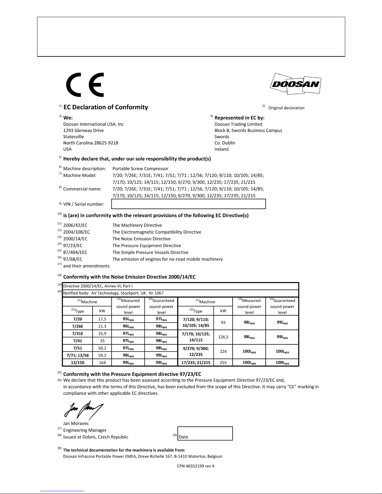
Machine models represented in this manual may be used in various locations world−wide. Machines sold and shipped
into European Union Territories require that the machine display the CE Mark and conform to various directives. In
such cases, the design specification of this machine has been certified as complying with EC directives. Any
modification to any part is absolutely prohibited and would result in the CE Certification and marking being rendered
invalid. A declaration of that conformity follows:
SAMPLE


CALIFORNIA
Proposition 65 Warning
Diesel engine exhaust and some of its constituents are known to
the State of California to cause cancer, birth defects, and other
reproductive harm.

CONTENTS & ABBREVIATIONS
1
7/26E, 7/31E, 7/41, 7/51
1 CONTENTS
2 FOREWORD
3 WARRANTY
10 DECALS
16 NOISE EMISSION
20 MAINTENANCE RECORD FOR NOISE
EMISSION CONTROL AND EXTENDED
WARRANTY
21 SAFETY
24 GENERAL INFORMATION
Dimensions
Data
30 OPERATING INSTRUCTIONS
Commissioning
Prior to starting
Starting
Stopping
Emergency stopping
Re−starting
Monitoring during operation
Decommissioning
34 MAINTENANCE
Routine maintenance
Lubrication
Speed & pressure regulation
Torque settings table
Compressor lubrication
46 MACHINE SYSTEMS
Electrical system
Piping & instrumentation system
56 FAULT FINDING
58 OPTIONS
Lubricator.
Safety.
General Information.
Operating Instructions.
Maintenance.
Fault Finding.
Generator.
Safety.
General Information.
Operating Instructions.
Maintenance.
Fault Finding.
66 ENGINE INSTRUCTION MANUAL
ABBREVIATIONS & SYMBOLS
#### Contact Ingersoll−Rand for serial number
−>#### Up to Serial No.
####−> From Serial No.
* Not illustrated
† Option
AR As required
HA High ambient machine
F.H.R.G. Fixed height running gear
V.H.R.G. Variable height running gear
bg Bulgarian
cs Czech
da Danish
de German
el Greek
en English
es Spanish
et Estonian
fi Finnish
fr French
hu Hungarian
it Italian
lt Lithuanian
lv Latvian, Lettish
mt Maltese
nl Dutch
no Norwegian
pl Polish
pt Portuguese
ro Romanian
ru Russian
sk Slovak
sl Slovenian
sv Swedish
zh Chinese
FOREWORD
2
7/26E, 7/31E, 7/41, 7/51
The contents of this manual are considered to be proprietary and
confidential to Ingersoll−Rand and should not be reproduced without
the prior written permission of Ingersoll−Rand.
Nothing contained in this document is intended to extend any
promise, warranty or representation, expressed or implied, regarding
the Ingersoll−Rand products described herein. Any such warranties or
other terms and conditions of sale of products shall be in accordance
with the standard terms and conditions of sale for such products, which
are available upon request.
This manual contains instructions and technical data to cover all
routine operation and scheduled maintenance tasks by operation and
maintenance staff. Major overhauls are outside the scope of this
manual and should be referred to an authorised Ingersoll−Rand service
department.
The design specification of this machine has been certified as
complying with EC directives. As a result:
(a) Any machine modifications are strictly prohibited, and will invalidate
EC certification.
(b) A unique specification for USA/Canada is adopted and tailored to
the territory.
All components, accessories, pipes and connectors added to the
compressed air system should be:
. of good quality, procured from a reputable manufacturer and,
wherever possible, be of a type approved by Ingersoll−Rand.
. clearly rated for a pressure at least equal to the machine maximum
allowable working pressure.
. compatible with the compressor lubricant/coolant.
. accompanied with instructions for safe installation, operation and
maintenance.
Details of approved equipment are available from Ingersoll−Rand
Service departments.
The use of repair parts / lubricants / fluids other than those included
within the Ingersoll−Rand approved parts list may create hazardous
conditions over which Ingersoll−Rand has no control. Therefore
Ingersoll−Rand cannot be held responsible for equipment in which
non−approved repair parts are installed.
Ingersoll−Rand reserves the right to make changes and
improvements to products without notice and without incurring any
obligation to make such changes or add such improvements to
products sold previously.
The intended uses of this machine are outlined below and examples
of unapproved usage are also given, however Ingersoll−Rand cannot
anticipate every application or work situation that may arise.
IF IN DOUBT CONSULT SUPERVISION.
This machine has been designed and supplied for use only in the
following specified conditions and applications:
. Compression of normal ambient air containing no known or
detectable additional gases, vapours. or particles
. Operation within the ambient temperature range specified in the
GENERAL INFORMATION section of this manual.
. Generation of electricity at 110v (1ph) with centre tap earth, 230v
(1ph), 230v (3ph) and 400v (3ph) / 230v (1ph) nominal at 50 Hertz.
(WDG)
The use of the machine in any of the situation types listed in
table 1:−
a) Is not approved by Ingersoll−Rand,
b) May impair the safety of users and other persons, and
c) May prejudice any claims made against Ingersoll−Rand.
TABLE 1
Use of the machine to produce compressed air for:
a) direct human consumption
b) indirect human consumption, without suitable filtration and purity
checks.
Use of the machine outside the ambient temperature range
specified in the GENERAL INFORMATION SECTION of this manual.
This machine is not intended and must not be used in potentially
explosive atmospheres, including situations where flammable gases
or vapours may be present.
Use of the machine fitted with non Ingersoll−Rand approved
components / lubricants / fluids.
Use of the machine with safety or control components missing or
disabled.
Use of the machine for storage or transportation of materials inside
or on the enclosure except when contained within the toolbox.
GENERATOR
Use of the generator to supply load(s) greater than those specified.
Use of unsafe or unserviceable electrical equipment connected to
the generator.
Use of electrical equipment:
(a) Having incorrect voltage and/or frequency ratings.
(b) Containing computer equipment and/or similar electronics.
The company accepts no responsibility for errors in translation of
this manual from the original English version.
© COPYRIGHT 2010
DOOSAN COMPANY

WARRANTY
3
7/26E, 7/31E, 7/41, 7/51
Ingersoll−Rand, through its distributor, warrants that each item of
equipment manufactured by it and delivered hereunder to the initial
user will be free of defects in material and workmanship for a period of
three (3) months from initial operation or six (6) months from the date
of shipment to the initial user, whichever occurs first.
With respect to the following types of equipment, the warranty period
enumerated below will apply in lieu of the foregoing warranty period.
A. Aftercoolers − The earlier of nine (9) months from date of
shipment to or six (6) months from start up by initial user.
B. Portable Compressors, Portable Generator Sets −
9 Kva through to 550 Kva, Portable Light Towers and Air
Dryers − The earlier of twelve (12) months from shipment to or
the accumulation of 2,000 hours of service by the initial user.
2.5 Kva Through to 8 Kva − The earlier of twelve (12) months
from shipment to or the accumulation of 2,000 hours of operation
by the initial user.
Ingersoll−Rand will provide a new part or repaired part, at it’s sole
discretion, in place of any part which is found to be defective in
material or workmanship during the period described above.
Labor cost to replace the part is the responsibility of the initial
user.
C. Portable Compressor Air Ends − The earlier of twenty−four
(24) months from shipment to or the accumulation of 4,000 hours
of service by the initial user. For Air Ends, the warranty against
defects will include replacement of the complete Air End,
provided the original Air End is returned assembled and all
original seals are intact.
C1. Portable Compressor Airend Limited Extended Warranty −
The earlier of sixty (60) months from shipment to or the
accumulation of 10,000 hours of operation by the initial user. This
extended warranty is limited to defects in design or defective
material or workmanship in rotors, housings, bearings and gears
and provided all the following conditions are met:
The original air end is returned assembled and all original seals
are intact.
Continued use of genuine Ingersoll−Rand parts, fluids, oils and
filters.
Maintenance is performed at prescribed intervals by authorized
and properly trained service engineers.
D. Generator Alternator − 9 Kva through to 550 Kva. The earlier
of twenty−four (24) months from shipment to or the accumulation
of 4,000 hours of operation by the initial user.
2.5 Kva Through to 8 Kva − The earlier of twelve (12) months
from shipment to or the accumulation of 2,000 hours of operation
by the initial user.
E. Portable Light Tower Alternator − The earlier of twelve (12)
months from shipment to or the accumulation of 2,000 hours of
operation by the initial user. Light Source model only, the earlier
of twenty−four (24) months from shipment to or the accumulation
of 4,000 hours of operation by the initial user.
F. Ingersoll−Rand Engines − The earlier of twenty−four (24)
months from shipment to or the accumulation of 4,000 hours of
operation by the initial user.
G. Ingersoll−Rand Platinum Drive Train Limited Extended
Warranty − Platinum drive train refers to the Ingersoll−Rand
Engine and Airend combination. The earlier of sixty (60) months
from shipment to, or the accumulation of 10,000 hours of
operation by the initial user. The starter, alternator, fuel injection
system and all electrical components are excluded from this
extended warranty. The airend seal and drive coupling are
included in the warranty but airend drive belts are excluded. This
limited extended warranty is automatically available when
meeting the following conditions are met:
1. The original airend is returned assembled and unopened.
2. Continued use of genuine Ingersoll−Rand parts, fluids, oil and
filters.
3. Maintenance is performed at prescribed intervals by
authorized and properly trained service engineers.
Ingersoll−Rand shall be provided with such information as it
requires to confirm that these conditions have been complied
with.
H1. Construction Tools, (Portable Power range only) − Twelve
(12) months from shipment to initial user. Ingersoll−Rand will
provide a new part or repaired part, at it’s sole discretion, in place
of any part which is found to be defective in material or
workmanship during the period described above. Labor cost to
replace the part is the responsibility of the initial user.
H2. Construction Tools Limited Extended Warranty, (Portable
Power range only) − Thirty−six (36) months from shipment to
initial user. This extended warranty is automatically available
only when the tool is registered with Ingersoll−Rand by
completing and submitting the Warranty Registration form.
Ingersoll−Rand will provide a new part or repaired part, at it’s sole
discretion, in place of any part which is found to be defective in
material or workmanship during the period described above.
Labor cost to replace the part is the responsibility of the initial
user.
I. Spare Parts − Six (6) months from date of shipment to the initial
user.
Ingersoll−Rand will provide a new part or repaired part, at its sole
discretion, in place of any part that is found to be defective in material
and workmanship during the period described above. Such parts will
be repaired or replaced without charge to the initial user during normal
working hours at the place of business of an Ingersoll−Rand distributor
authorized to sell the type of equipment involved or other establishment
authorized by Ingersoll−Rand. User must present proof of purchase at
the time of exercising warranty.
The above warranties do not apply to failures occurring as a result of
abuse; misuse, negligent repairs, corrosion, erosion and normal wear
and tear, alterations or modifications made to the product without
express written consent of Ingersoll−Rand; or failure to follow the
recommended operating practices and maintenance procedures as
provided in the product’s operating and maintenance publications.
Accessories or equipment furnished by Ingersoll−Rand, but
manufactured by others, including, but not limited to, engines, tires,
batteries, engine electrical equipment, hydraulic transmissions,
carriers, shall carry only the manufacturers warranty, which
Ingersoll−Rand can lawfully assign to the initial user.
THE ABOVE WARRANTIES ARE IN LIEU OF ALL OTHER
WARRANTIES EXPRESSED OR IMPLIED, (EXCEPT THAT OF
TITLE), AND THERE ARE NO WARRANTIES OF
MERCHANTABILITY OR OF FITNESS FOR A PARTICULAR
PURPOSE.

WARRANTY
4
7/26E, 7/31E, 7/41, 7/51
GENERAL WARRANTY INFORMATION − ESA
COMMENTS
PORTABLE COMPRESSOR PACKAGE
12 MONTHS / 2,000
HOURS
COVERS CONTROLS, SWITCHES, SHEET METAL,
RADIATOR, OIL COOLER, RECEIVER, PIPEWORK,
ELECTRICAL CIRCUIT ETC.
AIREND
24 MONTHS / 4,000
HOURS
60 MONTHS / 10,000 HOURS. EXTENDED LIMITED
WARRANTY AVAILABLE ON MAJOR COMPONENTS.
REFER TO OPERATOR’S MANUAL.
ENGINE SEE BELOW
2.5kVA − 8kVA
GENERATORS
PACKAGE
12 MONTHS / 2,000
HOURS
CONTACT IR NETWORK FOR WARRANTY (PARTS
ONLY NO LABOUR).
ALTERNATOR
12 MONTHS / 2,000
HOURS
CONTACT IR NETWORK FOR WARRANTY (PARTS
ONLY NO LABOUR).
ENGINE SEE BELOW
9kVA − 550kVA
GENERATORS
PACKAGE
12 MONTHS / 2,000
HOURS
COVERS CONTROLS, SWITCHES, SHEET METAL,
ELECTRICAL CIRCUIT ETC.
ALTERNATOR
24 MONTHS / 4,000
HOURS
CONTACT IR NETWORK FOR WARRANTY.
ENGINE SEE BELOW
LIGHT TOWER PACKAGE
12 MONTHS / 2,000
HOURS
COVERS CONTROLS, SWITCHES, SHEET METAL,
ELECTRICAL CIRCUIT ETC.
ALTERNATOR
12 MONTHS / 2,000
HOURS
EXTENDED WARRANTY OF 24 MONTHS / 4,000 HRS.
FOR LIGHTSOURCE INTRODUCED 8/16/99.
ENGINE SEE BELOW
ENGINES
MONTHS HOURS COMMENTS
CATERPILLAR 12
UNLIMITED
EXTENDED WARRANTY PROVIDED VIA ENGINE
SUPPLIER’S OWN APPROVED NETWORK AT TIME OF
PURCHASE.
CUMMINS 24 2,000 EXTENDED WARRANTY PROVIDED VIA ENGINE
SUPPLIER’S OWN APPROVED NETWORK AT TIME OF
PURCHASE.
PERKINS 12
UNLIMITED
IF UNDER 500 HOURS IN FIRST YEAR THEN BELOW
APPLIES.
24 1,000 ALL COMPONENTS COVERED EXCLUDING
INJECTORS.
JOHN DEERE
(IN COMPRESSORS)
24 2,000 5 YRS/5,000 HRS USING OEM FLUIDS AND FILTERS
WITH $250 DEDUCTABLE
(IN GENERATORS)
24 2,000 24 MONTHS / 4,000 HRS. AVAILABLE FROM IR WITH
USE OF GENUINE IR PARTS AND OILS AT
PRESCRIBED SERVICE INTERVALS. CONTACT IR
NETWORK.
DEUTZ 0 − 12
UNLIMITED ALL COMPONENTS COVERED.
13 − 24
UNLIMITED
MAJOR COMPONENTS COVERED. FURTHER
EXTENDED WARRANTY ON MAJOR COMPONENTS
PROVIDED VIA ENGINE SUPPLIER’S OWN APPROVED
NETWORK AT TIME OF PURCHASE.
INGERSOLL−RAND 24 4,000 EXTENDED WARRANTY OF 60 MONTHS / 10,000 HRS.
WHEN USING GENUINE INGERSOLL−RAND FLUIDS
AND PARTS ON MAJOR COMPONENTS.
WARRANTY
5
7/26E, 7/31E, 7/41, 7/51
KUBOTA
(North America only)
24 2,000 EXTENDED WARRANTY OF 36 MONTHS / 3,000 HRS.
ON MAJOR COMPONENTS, PARTS ONLY, AVAILABLE
FROM KUBOTA.
(Western Europe and Oceania)
24 2,000
NO EXTENDED WARRANTY AVAILABLE.
(Central and South America, Asia,
Middle East and Africa)
12 1,000
NO EXTENDED WARRANTY AVAILABLE.
MITSUBISHI 24 2,000 2YRS / 4,000 HRS USING IR FLUIDS AND FILTERS
VOLVO 24 2,000 2YRS / 4,000 HRS USING IR FLUIDS AND FILTERS
PARTS
MONTHS HOURS COMMENTS
INGERSOLL−RAND 6
UNLIMITED PARTS ONLY AVAILABLE FROM IR NETWORK.
AIREND EXCHANGE
MONTHS HOURS COMMENTS
AIREND
12 2,000 24 MONTHS / 4,000 HRS. AVAILABLE FROM IR
NETWORK.
CONSTRUCTION TOOLS
MONTHS HOURS COMMENTS
CONSTRUCTION TOOLS
12 N/A OPTIONAL 36 MONTHS EXTENDED WARRANTY
AVAILABLE FROM IR. ALL WARRANTY COVERS PARTS
ONLY REPLACEMENT.
NOTE: Actual warranty times may change.
Consult the Manufacturer’s warranty policy as shipped with each
new product.
WARRANTY
6
7/26E, 7/31E, 7/41, 7/51
Extended Limited Airend Warranty
Ingersoll−Rand Portable Compressor Division is pleased to announce the availability of extended limited airend warranty. Announcement of the
extended warranty coincides with the introduction of Pro−Te c
Compressor Fluid. Pro−Te c Compressor Fluid is an amber coloured fluid specially
formulated for Portable Compressors and is being provided as the factory filled fluid for all machines except 1 XHP650/900/1070
All machines have the standard airend warranty, − The earlier of 24 months from shipment to, or the accumulation of 4000 hours of service by the
initial user.
The warranty against defects will include replacement of the complete Airend, provided the original Airend is returned assembled and unopened.
The optional limited warranty is the earlier of 60 months from shipment to, or the accumulation of 10,000 hours of service. The optional warranty
is limited to defects in major components (rotors, housings, gears and bearings), and is automatically available when the following conditions are met:
1. The original airend is returned assembled and unopened.
2. Submissions of proof that Ingersoll−Rand fluid, filters and separators have been used. Refer to the Operation and Parts manual for the correct fluids,
filters and separator elements required.
3. Submissions of proof that maintenance intervals have been followed.
WARRANTY TIME *BARE AIREND **AIREND COMPONENTS
STANDARD 2YRS / 4,000HRS 100% PARTS & LABOUR 100% PARTS & LABOUR
OPTIONAL 5YRS / 10,000HRS 100% PARTS & LABOUR 0%
*BARE AIREND − pertains to major airend parts (rotors, housings, gears and bearings).
**AIREND COMPONENTS − pertains to auxiliary attachments to the bare airend (seals, pumps, valves, tubes, hoses, fittings and filter housing).
Pro−Te c and XHP505 Compressor Fluids are available from your local Ingersoll−Rand branch or distributor.
For units operating within the USA & Canada, call the Statesville Product Support Department on 1−800−633−5206
1
XHP650/900/1070/1170 will continue to use XHP505 and will have the extended warranty when above conditions are met.

WARRANTY
7
7/26E, 7/31E, 7/41, 7/51
WARRANTY REGISTRATION
FOR UNITS SOURCED FROM DUBLIN, IRELAND
Complete Machine Registration
To initiate the machine warranty, fill out the ”Warranty Registration” form 85040285 supplied as part of the machine documentation, keep a copy for
your records and mail the original to:
Doosan Warranty Team
Doosan Trading Limited
Block B, Swords Business Campus
Swords
County Dublin
Ireland
Fax: (+353) 1 870 7404
Email: doosanwarranty@dii.doosan.com
Note: Completion of this form validates the warranty.
Engine Registration:
I−R powered machines do not require separate engine registration.
Deutz require a separate engine registration form to be completed and mailed direct to their Cologne office. The form is supplied as part of the machine
documentation for Deutz powered machines.
Caterpillar, Cummins and Perkins do not require a separate registration form but they stipulate that any new engine should be registered with their local
dealer to initiate warranty.
You MUST provide proof of the “in−service” date when requesting engine warranty repairs.

WARRANTY
8
7/26E, 7/31E, 7/41, 7/51
WARRANTY REGISTRATION
FOR UNITS SOURCED FROM STATESVILLE, USA
Com
plete Machine Registration
Machines shipped to locations within the United States do not require a warranty registration unless the machine status changes (i.e. change of
ownership).
Machines shipped outside the United States require notification be made to initiate the machine warranty.
Fill out the Warranty Registration Form in this section, keep a copy for your records and
mail form to:
Doosan International USA, Inc
1293 Glenway Drive
Statesville
North Carolina 28625−9218
Attn: Warranty Department
Note: Completion of this form validates the warranty.
Engine Registration:
I−R powered machines do not require separate engine registration.
John Deere requires a separate engine registration be completed and mailed direct to John Deere.
Separate engine registration material is included with this literature package for John Deere powered machines.
All other engine manufacturers do not require a separate engine registration.
You MUST present proof of in−service date at time of requesting engine warranty service.

SAMPLE
WARRANTY
9
7/26E, 7/31E, 7/41, 7/51
PORTABLE POWER
EXTENDED WARRANTY REGISTRATION FORM
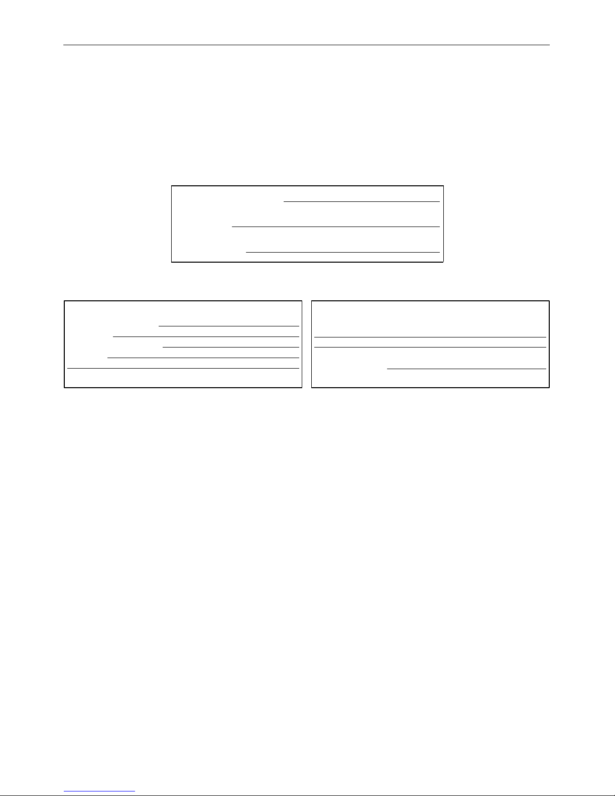
Customer Details Service Provider Details
Company Name : Service Provider / Distributor :
Contact Name : Branch Office :
Signature :
Company Address : Machine Details
Product Type :
Model :
Serial Number :
Engine Serial Number :
Engine Model Number :
Post / Zip Code : Airend Serial Number :
Country : Alternator Serial Number :
Phone Number : Date of start up :
Fax Number :
e−mail :
DECALS10
7/26E, 7/31E, 7/41, 7/51
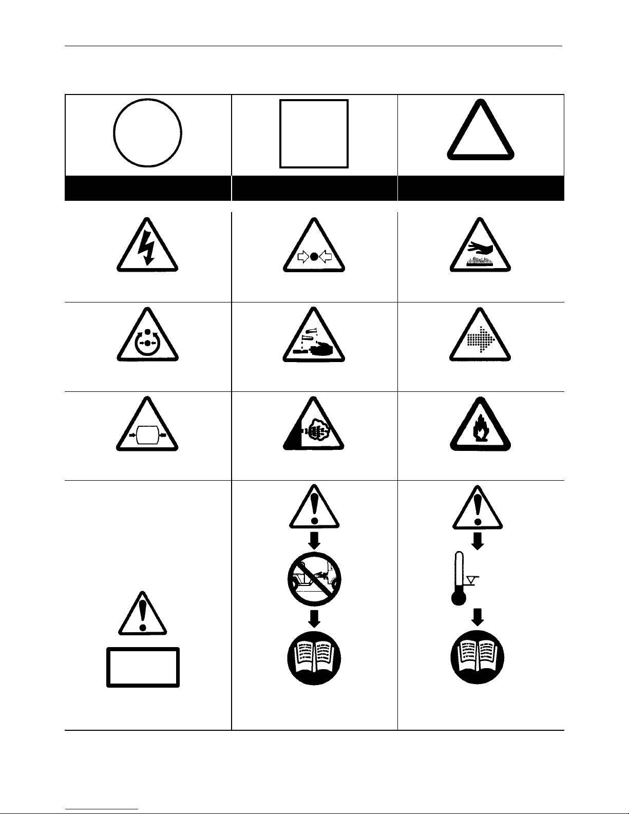
GRAPHIC FORM AND MEANING OF ISO SYMBOLS
Prohibition / Mandatory Information / Instructions Warning
WARNING: Electrical shock risk. WARNING − Pressurised component or
system.
WARNING − Hot surface.
WARNING − Pressure control. WARNING − Corrosion risk. WARNING − Air/gas flow or Air discharge.
WARNING − Pressurised vessel. WARNING − Hot and harmful exhaust gas. WARNING − Flammable liquid.
X,XBAR
0C
WARNING − Maintain correct tyre pressure.
(Refer to the GENERAL INFORMATION
section of this manual).
WARNING − Before connecting the tow bar
or commencing to tow consult the
operation and maintenance manual.
WARNING − For operating temperature
below 0C, consult the operation and
maintenance manual.
11
DECALS
7/26E, 7/31E, 7/41, 7/51
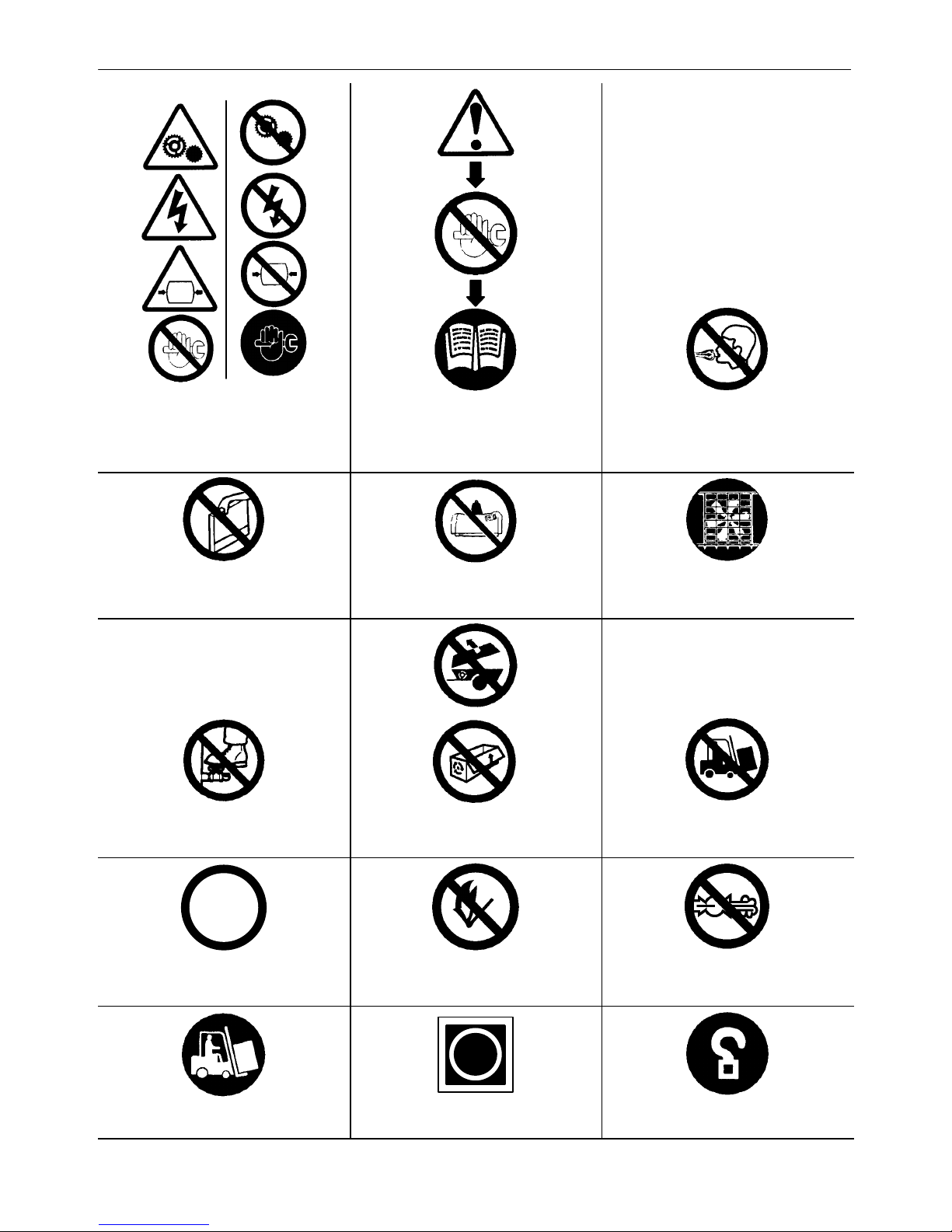
WARNING − Do not undertake any
maintenance on this machine until the
electrical supply is disconnected and the air
pressure is totally relieved.
WARNING − Consult the operation and
maintenance manual before commencing
any maintenance.
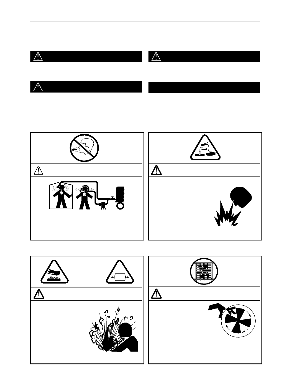
Do not breathe the compressed air from this
machine.
Do not remove the Operating and Maintenance
manual and manual holder from this machine.
Do not stack.
Do not operate the machine without the guard
being fitted.
Do not stand on any service valve or other
parts of the pressure system.
Do not operate with the doors or enclosure
open.
Do not use fork lift truck from this side.
XX
km/h
Do not exceed the trailer speed limit. No naked lights.
Do not open the service valve before the
airhose is attached.
Use fork lift truck from this side only. Emergency stop. Tie down point
DECALS12
7/26E, 7/31E, 7/41, 7/51
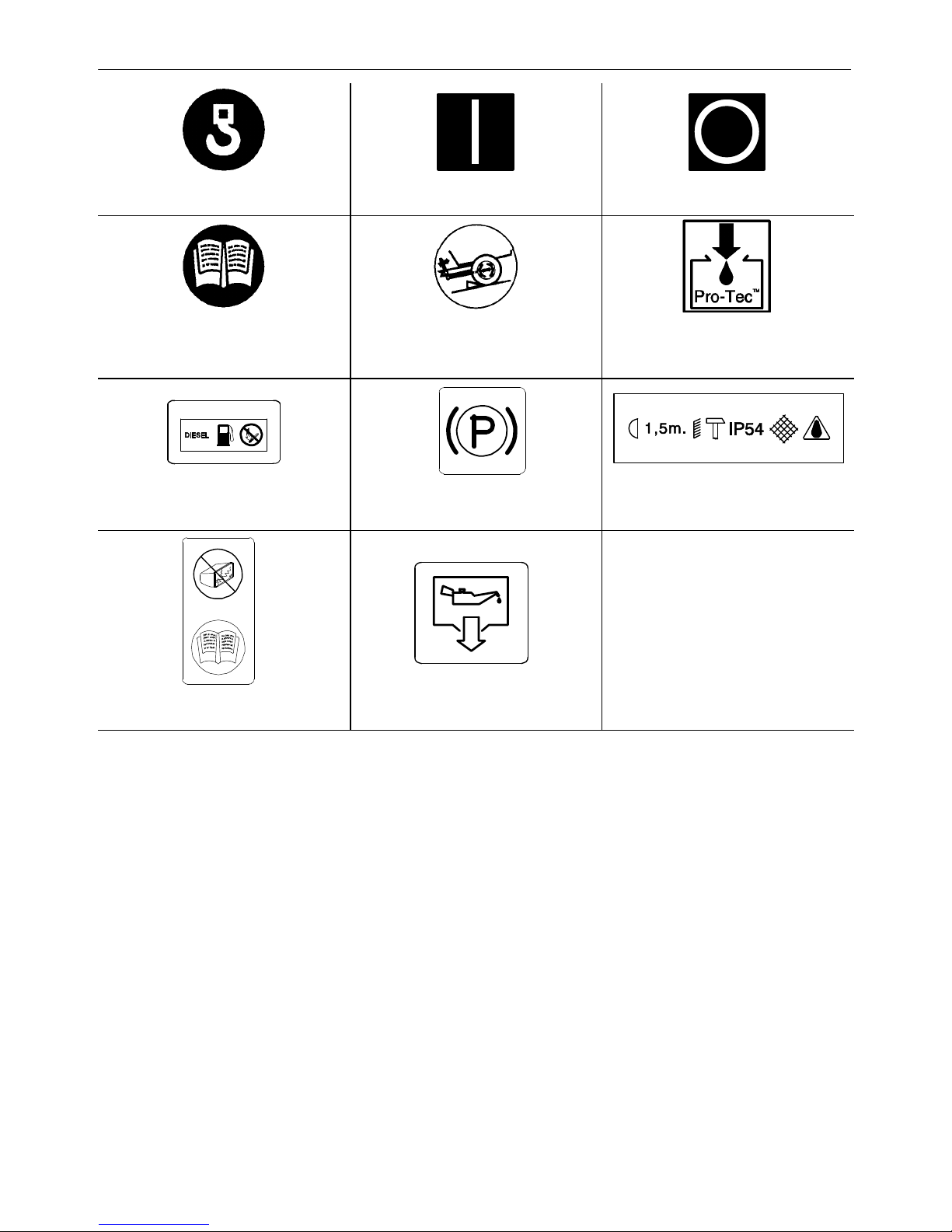
Lifting point. On (power). Off (power).
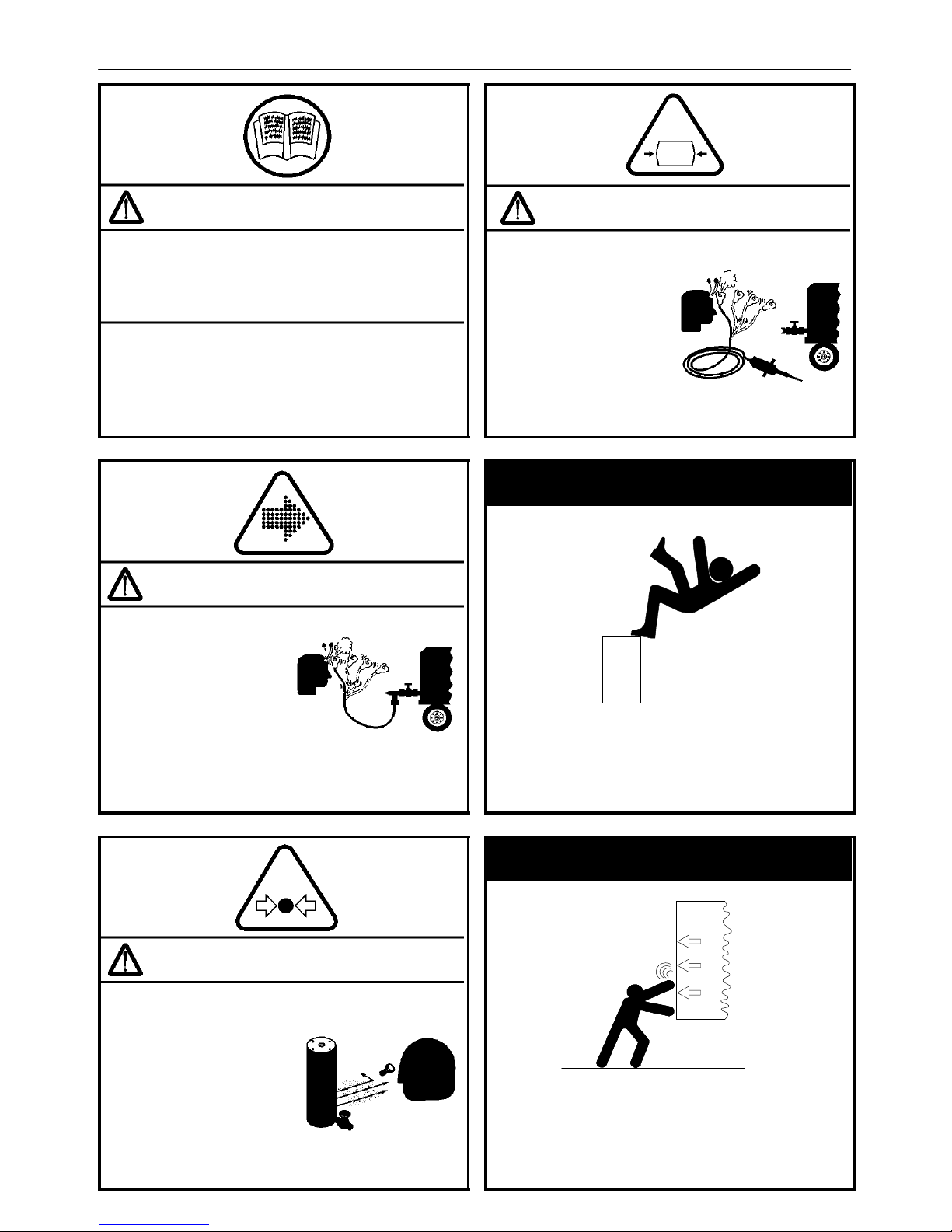
Read the Operation and Maintenance manual
before operation or maintenance of this
machine is undertaken.
When parking use prop stand, handbrake and
wheel chocks.
Compressor oil filling
Diesel fuel
No open flame.
Parking brake.
Rough Service Designation.
Wet Location Operation.
Replace any cracked protective shield.
Oil drain.
13
DECALS
7/26E, 7/31E, 7/41, 7/51
Look for these signs on machines shipped to markets in North America, which point out potential hazards
to the safety of you and others. Read and understand thoroughly. Heed warnings and follow instructions.
If you do not understand, inform your supervisor.
DANGER
Red background
Indicates the presence of a hazard which WILL cause
serious injury, death or property damage, if ignored.
WARNING
Orange background
Indicates the presence of a hazard which CAN cause
serious injury, death or property damage, if ignored.
CAUTION
Yellow background
Indicates the presence of a hazard which WILL or can
cause injury or property damage, if ignored.
NOTICE
Blue background
Indicates important set−up, operating or maintenance
information.
DANGER
Air discharged from this machine can contain
carbon monoxide or other contaminants which
will cause serious injury or death.
Do not breathe this air.
WARNING
Hot pressurized fluid.
Can cause serious burns.
Do not open radiator while
hot.
WARNING
Trapped air pressure. Can
cause serious injury or
death.
Close service valve and
operate tool to vent trapped air
before performing any service.
WARNING
Rotating Fan Blade.
CAN cause serious injury.
Do NOT operate with guard
removed.
DECALS14
7/26E, 7/31E, 7/41, 7/51
Improper operation of this equipment.
CAN cause serious injury or death.
Read Operator’s Manual supplied with this machine
before operation or servicing.
WARNING
Modification or alteration of this machine.
CAN cause serious injury or death.
Do NOT alter or modify this machine without the
express written consent of the manufacturer.
WARNING
Disconnected Air Hoses
Whip. CAN cause
serious injury or death.
When using air tools attach
safety device
(OSHA Valve) at source of
air supply for each tool.
WARNING
High pressure air. Can
cause serious injury or
death.
Relieve pressure before
removing filler plugs/
caps, fittings or covers.
WARNING
Trapped air pressure.
Can cause serious injury
or death.
Close service valve and
operate tool to vent trapped
air before performing any
service.
WARNING
Falling off machine. CAN cause serious
injury or death.
Access Lifting Bail from inside machine.
WARNING
Door under pressure CAN cause serious
injury.
Use both hands to open door when machine
is running.

15
DECALS
7/26E, 7/31E, 7/41, 7/51
WARNING
Collapsing propstand.
Can cause serious injury.
Clamp propstand securely
Excessive towing speed.
Can cause serious injury or
death.
Do NOT exceed 65 mph (105
km/hr)
For Highway Towable Units.
WARNING
Excessive Towing Speed. CAN cause
serious injury or death.
Do NOT Tow on Highway.
Do NOT exceed 20 mph (32 km/h)
For Non−Highway Towable Machines
Safety Decals are available free of charge. Safety decals
are identified by the decal heading:
DANGER, WARNING or CAUTION.
Decal part numbers are on the bottom of each decal and
are also listed in the compressor’s parts manual. Submit
orders for Safety Decals to the Doosan Portable Power
EMEA Aftermarket Department. The no charge order
should contain only Safety Decals. Help promote product
safety! Assure that decals are present on the machines.
Replace decals that are not readable.
FREE SAFETY DECALS!

NOISE EMISSION
16
7/26E, 7/31E, 7/41, 7/51
This section pertains only to machines distributed within the
United States.
WARNING
TAMPERING WITH NOISE CONTROL SYSTEM PROHIBITED
Federal law prohibits the following acts or the causing thereof:
(1) The removal or rendering inoperative by any persons, other than for purposes of maintenance, repair, or replacement, of any device or element of
design incorporated into any new compressor for the purpose of noise control prior to its sale or delivery to the ultimate purchaser or while it is in use;
or (2) the use of the compressor after such device or element of design has been removed or rendered inoperative by any person.
Among those acts included in the prohibition against tampering are these:
1. Removal or rendering inoperative any of the following:
a. the engine exhaust system or parts thereof
b. the air intake system or parts thereof
c. enclosure or parts thereof
2. Removal of any of the following:
a. fan shroud
b. vibration mounts
c. sound absorption material
3. Operation of the compressor with any of the enclosure doors open.
Compressor Noise Emission Control Information
A. The removal or rendering inoperative, other than for the purpose of maintenance, repair, or replacement of any noise control device or element of
design incorporated into this compressor in compliance with the noise control act;
B. The use of this compressor after such device or element of design has been removed or rendered inoperative.
Note: the above information applies only to units that are built in compliance with the U.S. Environmental Protection Agency.
Ingersoll−Rand Company reserves the right to make changes or add improvements without notice and without incurring any obligation to make such
changes or add such improvements to products sold previously.
The Purchaser is urged to include the above provisions in any agreement for any resale of this compressor.
17
NOISE EMISSION
7/26E, 7/31E, 7/41, 7/51
NOISE EMISSION CONTROL
MAINTENANCE LOG
COMPRESSOR MODEL
SERIAL NO.
USER UNIT NO.
UNIT IDENTIFICATION
ENGINE MAKE & MODEL:
SERIAL NO.:
PURCHASER OR OWNER:
ADDRESS:
DEALER OR DISTRIBUTOR
FROM WHOM PURCHASED:
DATE PURCHASED:
The Noise Control Act of 1972 (86 Stat. 1234) prohibits tampering with the noise control system of any compressor manufactured and sold under
the above regulations, specifically the following acts or the causing thereof:
(1) The removal or rendering inoperative by any persons, other than for purposes of maintenance, repair, or replacement, of any device or element of
design incorporated into any new compressor for the purpose of noise control prior to its sale or delivery to the ultimate purchaser or while it is in use;
or (2) the use of the compressor after such a device or element of design has been removed or rendered inoperative by any person.
NOISE EMISSION WARRANTY
The manufacturer warrants to the ultimate purchaser and each subsequent purchaser that this air compressor was designed, built and equipped
to conform at the time of sale to the first retail purchaser, with all applicable U.S. EPA Noise Control Regulations.
This warranty is not limited to any particular part, component, or system of the air compressor. Defects in the design, assembly, or in any part,
component, or system of the compressor which, at the time of sale to the first retail purchaser, caused noise emissions to exceed Federal Standards
are covered by this warranty for the life of the air compressor. (40FR204.58−1).

NOISE EMISSION
18
7/26E, 7/31E, 7/41, 7/51
INTRODUCTION
The unit for which this Maintenance Log is provided conforms to U.S. E.P.A. Regulations for Noise Emissions, applicable to Portable Air
Compressors.
The purpose of this book is to provide (1) the Maintenance Performance Schedule below for all required noise emission controls and (2) space
so that the purchaser or owner can record what maintenance was done, by whom, where and when. Detailed instructions on the maintenance items
below are given on the following page.
MAINTENANCE SCHEDULE
ITEM AREA PERIOD
A.
COMPRESSED AIR LEAKS AS DETECTED
B.
SAFETY AND CONTROL SYSTEMS AS DETECTED
C.
ACOUSTIC MATERIALS DAILY
D.
FASTENERS 100 HOURS
E.
ENCLOSURE PANELS 100 HOURS
F.
AIR INTAKE & ENGINE EXHAUST 100 HOURS
G.
COOLING SYSTEMS 250 HOURS
H.
ISOLATION MOUNTS 250 HOURS
I.
ENGINE OPERATION SEE OPERATOR’S MANUAL
J.
FUELS & LUBRICANTS SEE OPERATOR’S MANUAL

19
NOISE EMISSION
7/26E, 7/31E, 7/41, 7/51
A. COMPRESSED AIR LEAKS
Correct all compressed air leaks during the first shutdown period
after discovery. If severe enough to cause serious noise problems and
efficiency loss, shut down immediately and correct the leak(s).
B. SAFETY AND CONTROL SYSTEMS
Repair or replace all safety and control systems or circuits as
malfunction occurs. No compressor should be operated with either
system bypassed, disabled, or nonfunctional.
C. ACOUSTIC MATERIALS
In daily inspections, observe these materials. Maintain all
acoustic material as nearly as possible in its original condition. Repair
or replace all sections that have: 1) sustained damage, 2) have partially
separated from panels to which they were attached, 3) are missing, or
have otherwise deteriorated due to severe operating or storage
conditions.
D. FASTENERS
All fasteners such as hinges, nuts, bolts, clamps, screws, rivets
and latches should be inspected for looseness after each 100 hours of
operation. They should be retightened, repaired, or − if missing −
replaced immediately to prevent subsequent damage and noise
emission increase.
E. ENCLOSURE PANELS
Enclosure panels should also be inspected at 100 hour
operational intervals. All panels that are warped, punctured, torn, or
otherwise deformed, such that their noise containment function is
reduced, should be repaired or replaced before the next operation
interval. Doors, access panels, and hatch closures especially, should
be checked and adjusted at this time to insure continuous sealing
between gasket or acoustic material and the mating frame.
F. AIR INTAKE AND ENGINE EXHAUST
Engine and compressor air intake and engine exhaust systems
should be inspected after each 100 hours of operation for loose,
damaged, or deteriorated components. Repairs or replacements
should be made before the next period of use.
G. COOLING SYSTEMS
All components of the cooling systems for engine water and
compressor oil should be inspected every 250 hours of use. Any
discrepancies found should be corrected before placing the unit back
in operation. Unrestricted airflow over the radiator and oil cooler must
be maintained at all times during operation.
H. ISOLATION MOUNTS
Engine/airend isolation mounts should be inspected after each
250 hours of operation. Those mounts with cracks or splits in the
molded rubber, or with bent or broken bolts due to operation or storage
in severe environments, all should be replaced with equivalent parts.
I. ENGINE OPERATION
Inspect and maintain engine condition and operation as
recommended in the manuals supplied by the engine manufacturer.
J. FUELS AND LUBRICANTS
Use only the types and grades of fuels and lubricants
recommended in the Ingersoll−Rand Company and Engine
Manufacturer’s Operator and Maintenance Manuals.

MAINTENANCE RECORD FOR NOISE EMISSION CONTROL AND EXTENDED WARRANTY
20
7/26E, 7/31E, 7/41, 7/51
MAINTENANCE RECORD FOR NOISE EMISSION CONTROL AND EXTENDED WARRANTY
ITEM NO. DESCRIPTION OF WORK OR
COMMENTS
HOURMETER
READING
MAINT/INSPECT
DATE
LOCATION
CITY/STATE
WORK DONE BY
(NAME)

SAFETY
21
7/26E, 7/31E, 7/41, 7/51
WARNINGS
Warnings call attention to instructions which must be followed
precisely to avoid injury or death.
CAUTIONS
Cautions call attention to instructions which must be followed
precisely to avoid damaging the product, process or its surroundings.
NOTES
Notes are used for supplementary information.
General Information
Never operate unit without first observing all safety warnings and
carefully reading the operation and maintenance manual shipped from
the factory with this machine.
Ensure that the operator reads and understands the decals and
consults the manuals before maintenance or operation.
Ensure that the Operation and Maintenance manual, and the
manual holder, are not removed permanently from the machine.
Ensure that maintenance personnel are adequately trained,
competent and have read the Maintenance Manuals.
Make sure that all protective covers are in place and that the
canopy/doors are closed during operation.
The specification of this machine is such that the machine is not
suitable for use in flammable gas risk areas. If such an application is
required then all local regulations, codes of practice and site rules must
be observed. To ensure that the machine can operate in a safe and
reliable manner, additional equipment such as gas detection, exhaust
spark arrestors, and intake (shut−off) valves may be required,
dependant on local regulations or the degree of risk involved.
A weekly visual check must be made on all fasteners/fixing screws
securing mechanical parts. In particular, safety−related parts such as
coupling hitch, drawbar components, road−wheels, and lifting bail
should be checked for total security.
All components which are loose, damaged or unserviceable, must
be rectified without delay.
Air discharged from this machine may contain carbon monoxide or
other contaminants which will cause serious injury or death. Do not
breathe this air.
This machine produces loud noise with the doors open or service
valve vented. Extended exposure to loud noise can cause hearing loss.
Always wear hearing protection when doors are open or service valve
is vented.
Never inspect or service unit without first disconnecting battery
cable(s) to prevent accidental starting.
Do not use petroleum products (solvents or fuels) under high
pressure as this can penetrate the skin and result in serious illness.
wear eye protection while cleaning unit with compressed air to prevent
debris from injuring eye(s).
Rotating fan blade can cause serious injury. Do not operate without
guard in place.
Use care to avoid contacting hot surfaces (engine exhaust manifold
and piping, air receiver and air discharge piping, etc.).
Ether is an extremely volatile, highly inflammable gas. When it is
specified as a starting aid, use sparingly. DO NOT USE ETHER IF THE
MACHINE HAS GLOW PLUG STARTING AID OR ENGINE DAMAGE
WILL RESULT.
Never operate unit with guards, covers or screens removed. Keep
hands, hair, clothing, tools, blow gun tips, etc. well away from moving
parts.
Compressed air
Compressed air can be dangerous if incorrectly handled. Before
doing any work on the unit, ensure that all pressure is vented from the
system and that the machine cannot be started accidentally.
Ensure that the machine is operating at the rated pressure and that
the rated pressure is known to all relevant personnel.
All air pressure equipment installed in or connected to the machine
must have safe working pressure ratings of at least the machine rated
pressure.
If more than one compressor is connected to one common
downstream plant, effective check valves and isolation valves must be
fitted and controlled by work procedures, so that one machine cannot
accidentally be pressurised / over pressurised by another.
Compressed air must not be used for a direct feed to any form of
breathing apparatus or mask.
High Pressure Air can cause serious injury or death. Relieve
pressure before removing filler plugs/caps, fittings or covers.
Air pressure can remain trapped in air supply line which can result
in serious injury or death. Always carefully vent air supply line at tool
or vent valve before performing any service.
The discharged air contains a very small percentage of compressor
lubricating oil and care should be taken to ensure that downstream
equipment is compatible.
If the discharged air is to be ultimately released into a confined
space, adequate ventilation must be provided.
When using compressed air always use appropriate personal
protective equipment.
All pressure containing parts, especially flexible hoses and their
couplings, must be regularly inspected, be free from defects and be
replaced according to the Manual instructions.
Avoid bodily contact with compressed air.
The safety valve located in the separator tank must be checked
periodically for correct operation.
Whenever the machine is stopped, air will flow back into the
compressor system from devices or systems downstream of the
machine unless the service valve is closed. Install a check valve at the
machine service valve to prevent reverse flow in the event of an
unexpected shutdown when the service valve is open.

SAFETY
22
7/26E, 7/31E, 7/41, 7/51
Disconnected air hoses whip and can cause serious injury or death.
Always attach a safety flow restrictor to each hose at the source of
supply or branch line in accordance with OSHA Regulation 29CFR
Section 1926.302(b).
Never allow the unit to sit stopped with pressure in the
receiver−separator system.
Materials
The following substances may be produced during the operation of
this machine:
. brake lining dust
. engine exhaust fumes
AVOID INHALATION
Ensure that adequate ventilation of the cooling system and exhaust
gases is maintained at all times.
The following substances are used in the manufacture of this
machine and may be hazardous to health if used incorrectly:
. compressor lubricant
. engine lubricant
. preservative grease
. rust preventative
. diesel fuel
. battery electrolyte
AVOID INGESTION, SKIN CONTACT AND INHALATION OF
FUMES.
Should compressor lubricant come into contact with the eyes, then
irrigate with water for at least 5 minutes.
Should compressor lubricant come into contact with the skin, then
wash off immediately.
Consult a physician if large amounts of compressor lubricant are
ingested.
Consult a physician if compressor lubricant is inhaled.
Never give fluids or induce vomiting if the patient is unconscious or
having convulsions.
Safety data sheets for compressor and engine lubricants should be
obtained from the lubricant supplier.
Never operate the engine of this machine inside a building without
adequate ventilation. Avoid breathing exhaust fumes when working on
or near the machine.
This machine may include such materials as oil, diesel fuel,
antifreeze, brake fluid, oil/air filters and batteries which may require
proper disposal when performing maintenance and service tasks.
Contact local authorities for proper disposal of these materials.
Battery
A battery contains sulphuric acid and can give off gases which are
corrosive and potentially explosive. Avoid contact with skin, eyes and
clothing. In case of contact, flush area immediately with water.
DO NOT ATTEMPT TO SLAVE START A FROZEN BATTERY
SINCE THIS MAY CAUSE IT TO EXPLODE.
Exercise extreme caution when using booster battery. To jump
battery, connect ends of one booster cable to the positive (+) terminal
of each battery. Connect one end of other cable to the negative (−)
terminal of the booster battery and other end to a ground connection
away from dead battery (to avoid a spark occurring near any explosive
gases that may be present). After starting unit, always disconnect
cables in reverse order.
Radiator
Hot engine coolant and steam can cause injury. Ensure that the
radiator filler cap is removed with due care and attention.
Do not remove the pressure cap from a HOT radiator. Allow radiator
to cool down before removing pressure cap.
Generator sets
The generator set is designed for safety in use. However, the
responsibility for safe operation rests with those who install, use and
maintain it. The following safety precautions are offered as a guide,
which, if conscientiously followed, will minimise the possibility of
accidents throughout the useful life of this equipment.
Emergency Stop Controls
Important Note:− In addition to the key operated emergency stop
control on the main control panel, a second control is provided at the
socket control panel in the event of electrical hazards associated with
generator operation. Use this second control to immediately isolate all
electrical power to all sockets, then use the key control to stop the
engine.
Operation of the generator must be in accordance with recognised
electrical codes and local health and safety codes.
The generator set should be operated by those who have been
trained in its use and delegated to do so, and who have read and
understand the operator’s manual. Failure to follow the instructions,
procedures and safety precautions in the manual may increase the
possibility of accidents and injuries.
Do not start the generator set unless it is safe to do so. Do not
attempt to operate the generator set with a known unsafe condition. Fit
a danger notice to the generator set and render it inoperative by
disconnecting the battery and disconnecting all ungrounded
conductors so others who may not know of the unsafe condition will not
attempt to operate it until the condition is corrected.
An earth point is provided beneath the socket outlets.
The generator set should only be used with the earth point
connected directly to the general earth/ground mass. An earth spike kit
is available as an optional extra for this purpose (refer to the parts
catalogue).
WARNING: DO NOT OPERATE THE MACHINE UNLESS IT HAS
BEEN SUITABLY EARTHED.
Generator sets must be connected to the load only by trained and
qualified electricians who have been delegated to do so, and when
required by applicable regulations, their work should be inspected, and
accepted by the inspection agency having authority, prior to attempting
to operate the generator set.
Do not make contact with electrically energised parts of the
generator set and/or interconnecting cables or conductors with any
part of the body or with any non−insulated conductive object.

SAFETY
23
7/26E, 7/31E, 7/41, 7/51
Make sure the generator set is effectively grounded in accordance
with all applicable Regulations prior to attempting to make or break load
connections and prior to attempting operation.
Do not attempt to make or break electrical connections to generator
sets standing in water or on wet ground.
Prior to attempting to make or break electrical connections at the
generator set, stop the engine, disconnect the battery and disconnect
and lock out the ungrounded conductors at the load end.
Keep all parts of the body and any hand−held tools or other
conductive objects, away from exposed live parts of the generator set
engine electrical system. Maintain dry footing, stand on insulating
surfaces and do not contact any other portion of the generator set when
making adjustments or repairs to exposed live parts of the generator
set engine electrical system.
Replace the generator set terminal compartment cover as soon as
connections have been made or broken. Do not operate the generator
set without the terminal cover secured firmly in place.
Close and lock all access doors when the generator set is left
unattended.
Do not use extinguishers intended for Class A or Class B fires on
electrical fires. Use only extinguishers suitable for class BC or class
ABC fires.
Keep the towing vehicle or equipment carrier, generator set,
connecting cables, tools and all personnel at least 3 metres from all
power lines and buried power cables, other than those connected to the
generator set.
Attempt repairs only in clean, dry, well lighted and ventilated areas.
Connect the generator set only to loads and/or electrical systems
that are compatible with its electrical characteristics and that are within
it’s rated capacity.
Transport
When loading or transporting machines ensure that the specified
lifting and tie down points are used.
When loading or transporting machines ensure that the towing
vehicle, its size, weight, towing hitch and electrical supply are all
suitable to provide safe and stable towing at speeds either, up to the
legal maximum for the country in which it is being towed or, as specified
for the machine model if lower than the legal maximum.
Ensure that the maximum trailer weight does not exceed the
maximum gross weight of the machine (by limiting the equipment load),
limited by the capacity of the running gear.
Note:
Gross mass (on data plate) is for the basic machine and fuel only,
excluding any fitted options, tools, equipment and foreign materials.
Before towing the machine, ensure that:−
. the tyres and towing hitch are in a serviceable condition.
. the canopy is secure.
. all ancillary equipment is stored in a safe and secure manner.
. the brakes and lights are functioning correctly and meet necessary
road traffic requirements.
. break-away cables/safety chains are connected to the towing
vehicle.
The machine must be towed in a level attitude in order to maintain
correct handling, braking and lighting functions. This can be achieved
by correct selection and adjustment of the vehicle towing hitch and, on
variable height running gear, adjustment of the drawbar.
To ensure full braking efficiency, the front (towing eye) section must
always be set level.
When adjusting variable height running gear:−
Ensure front (towing eye) section is set level
When raising towing eye, set rear joint first, then front joint.
When lowering towing eye, set front joint first, then rear joint.
After setting, fully tighten each joint by hand and then tighten further to
the next pin. Refit the pin.
When parking always use the handbrake and, if necessary, suitable
wheel chocks.
Make sure wheels, tyres and tow bar connectors are in safe
operating condition and tow bar is properly connected before towing.
Safety chains / connections and their adjustment
The legal requirements for the joint operation of the breakaway
cable and safety chains are as yet unidentified by 71/320/EEC or UK
regulations. Consequently we offer the following advice / instructions.
Where brakes only are fitted:
a) Ensure that the breakaway cable is securely coupled to the
handbrake lever and also to a substantial point on the towing vehicle.
b) Ensure that the effective cable length is as short as possible, whilst
still allowing enough slackness for the trailer to articulate without the
handbrake being applied.
Where brakes and safety chains are fitted:
a) Loop the chains onto the towing vehicle using the towing vehicle
hitch as an anchorage point, or any other point of similar strength.
b) Ensure that the effective chain length is as short as possible whilst
still allowing normal articulation of the trailer and effective operation of
the breakaway cable.
Where safety chains only are fitted:
a) Loop the chains onto the towing vehicle using the towing vehicle
hitch as an anchorage point, or any other point of similar strength.
b) When adjusting the safety chains there should be sufficient free
length in the chains to allow normal articulation, whilst also being short
enough to prevent the towbar from touching the ground in the event of
an accidental separation of the towing vehicle from the trailer.
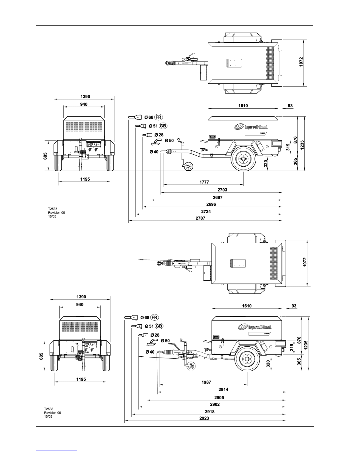
GENERAL INFORMATION
24
7/26E, 7/31E, 7/41, 7/51
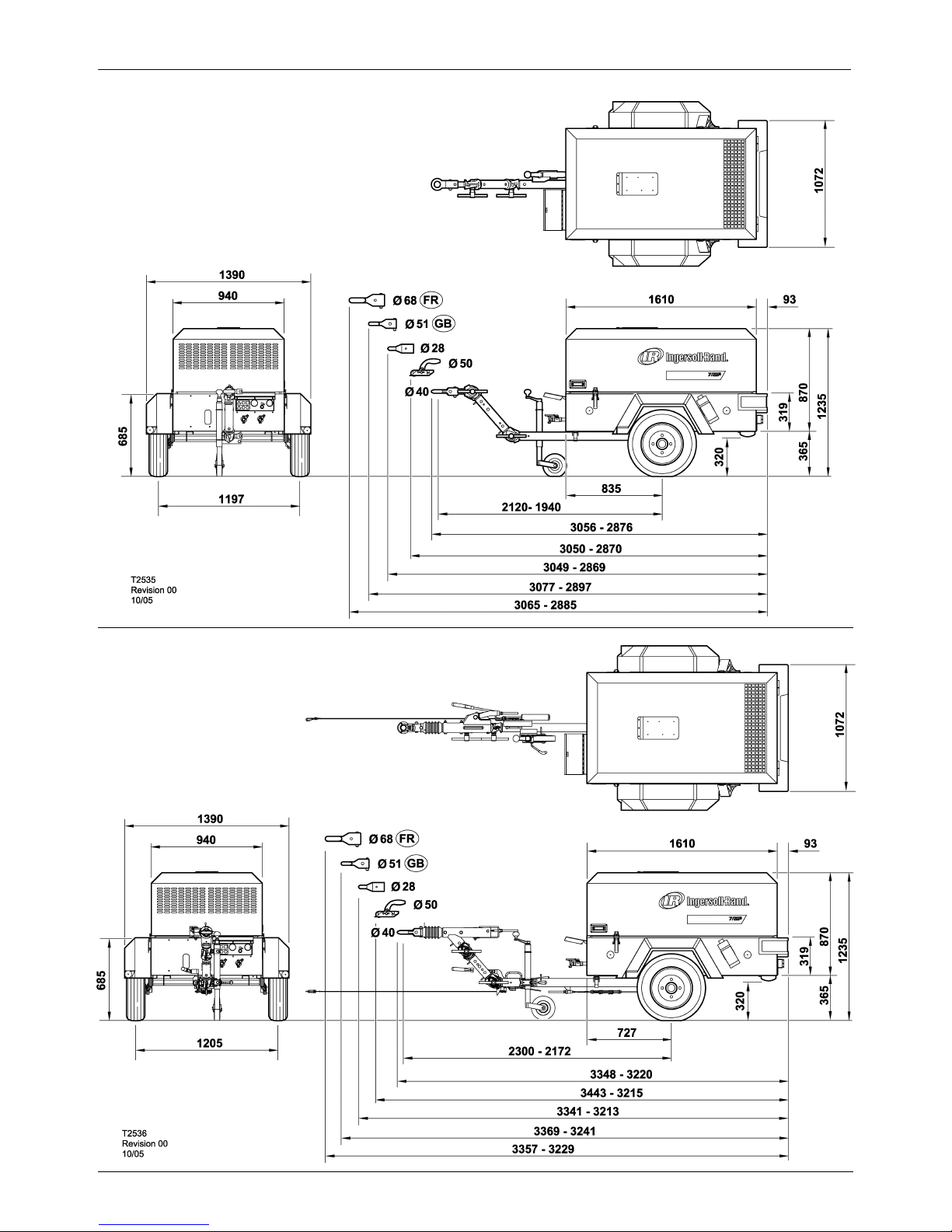
7/26E, 7/31E VARIABLE HEIGHT RUNNING GEAR
Unbraked version (Knott)
7/26E, 7/31E VARIABLE HEIGHT RUNNING
GEAR
Braked version (Knott)
GENERAL INFORMATION
25
7/26E, 7/31E, 7/41, 7/51
7/26E 7/31E FIXED HEIGHT RUNNING
GEAR
Unbraked version (Knott)
7/26E, 7/31E FIXED HEIGHT RUNNING GEAR
Braked version (Knott)
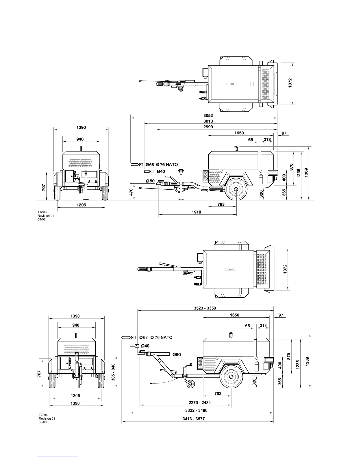
GENERAL INFORMATION
26
7/26E, 7/31E, 7/41, 7/51
7/41 FIXED HEIGHT RUNNING GEAR
Braked version (Knott)
7/41 VARIABLE HEIGHT RUNNING GEAR
Braked version (Knott)
 Loading...