

Page 1
OPERATOR’S MANUAL
INCLUDING: SPECIFICATIONS, SERVICE KITS, GENERAL INFORMATION, PARTS, TROUBLESHOOTING RELEASED: 11-10-06
4.125 SQ.” MOTOR
67314-B
67314-B
REVISED: 5-17-10
(REV. 03)
65 - 2000 P.S.I. RANGE
HYDRAULIC POWER MOTOR
READ THIS MANUAL CAREFULLY BEFORE INSTALLING,
OPERATING OR SERVICING THIS EQUIPMENT.
It is the responsibility of the employer to place this information in the hands of the operator. Keep for future reference.
SERVICE KITS
Use only genuine ARO® replacement parts to assure compat-
ible pressure rating and longest service life.
637450 pump repair kit, includes the necessary soft parts for
normal service of the entire pump.
SPECIFICATIONS
Models . . . . . . . . . . . . . . . . . . . . . . . . . . . . . . 67314-B
Type . . . . . . . . . . . . . . . . . . . . Hydraulic Operated Power Motor
Motor Size . . . . . . . . . . . . . . . . . . . . . . . . . . 4.125 sq.” (26.6 sq. cm)
Stroke . . . . . . . . . . . . . . . . . . . . . . . . . . . . . . . 6” (152 mm)
Hydraulic Inlet (female) . . . . . . . . . . . . . 1/2 - 14 N.P.T.F. - 2
Hydraulic Outlet (female) . . . . . . . . . . . 3/4 - 14 N.P.S.M.
Pump Construction . . . . . . . . . . . . . . . . . Carbon Steel
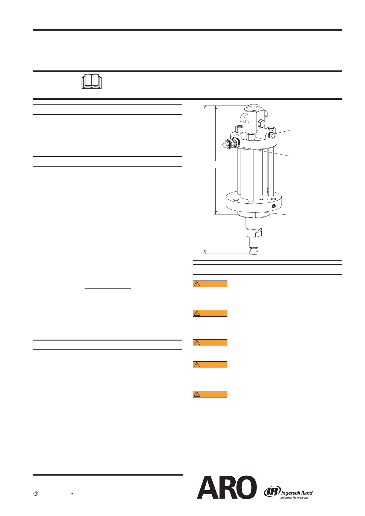
Dimension “A” . . . . . . . . . . . . . . . . . . . . . . 20-13/32” (518.2 mm)
Dimension “B” . . . . . . . . . . . . . . . . . . . . . . 15-11/16” (397.8 mm)
“C” Weep Hole . . . . . . . . . . . . . . . . . . . . . . 1/8 - 27 N.P.T.F. - 1
Motor Diameter . . . . . . . . . . . . . . . . . . . . . 8” (203.2 mm)
Maximum Temperature Limits . . . . . . 130° F (54° C)
Mounting Bracket available . . . . . . . .
Weight . . . . . . . . . . . . . . . . . . . . . . . . . . . . . . 37.75 lbs (17.1 kgs)
95933
B
A
OPERATING AND SAFETY PRECAUTIONS
Hydraulic Inlet
Hydraulic Outlet
C
Figure 1
PERFORMANCE
Inlet Pressure Range . . . . . . . . 65 - 2000 p.s.i. (4.5 - 137.9 bar)
Required H-power @ 50 c.p.m. . . . . . . 3.2 @ 1200 (82.8 bar)
Hydraulic ow required @ 50 c.p.m. 11 g.p.m. (41.6 l.p.m.)
Maximum Thrust generated . . . . . . . . 8250 lbs
Maximum recommended cycles / minute . . . . . . . . . 50
Noise Level . . . . . . . . . . . . . . . . . . . . . . . . . N/A
GENERAL DESCRIPTION
The 4.125 square inch hydraulic motor is a general purpose
power unit and is used on many ARO industrial 2-ball, 4-ball
and chop-check pumps. It utilizes tie rod type construction
for serviceability and connects to the various lower pump
ends by tie rods.
Due to frictional losses in the system, a greater horsepower
is required to run the motor. Power supplies generating less
than shown as required in the Performance Specifications
above will work with the motor but at a reduced pressure or
cycle rate.
WARNING
UAL INCLUDED FOR ADDITIONAL OPERATING AND
SAFETY PRECAUTIONS AND OTHER IMPORTANT INFORMATION.
WARNING
equipment failure resulting in severe injury or property damage. Do not exceed the maximum material
pressure of any component in the system.
WARNING
vent over-pressurization of the system and possible
component rupture.
WARNING
cause re. The unit is rated for operation up to 130° F
(54° C). Be sure return lines are sized larger than supply lines and similarly pressure rated.
WARNING
unit components without relieving hydraulic system
pressure rst. The high pressures involved could
cause serious injury.
NOTE: If this pump was purchased separately (not part
of a system), consult your sales representative for compatible dispensing accessories which will best match the
application. All accessories must be able to withstand the
maximum pressure developed by the pump.
A replacement warning label is available upon request,
pn \ 94576.
READ THE GENERAL INFORMATION MAN-
EXCESSIVE MATERIAL PRESSURE. Can cause
A pressure relief valve must be used to pre-
Excessive hydraulic oil temperature can
Never service or disassemble the unit or
INGERSOLL RAND COMPANY LTD
209 NORTH MAIN STREET – BRYAN, OHIO 43506
(800) 276-4658 FAX (800) 266-7016
www.ingersollrandproducts.com
© 2010 CCN 15267008
Page 2
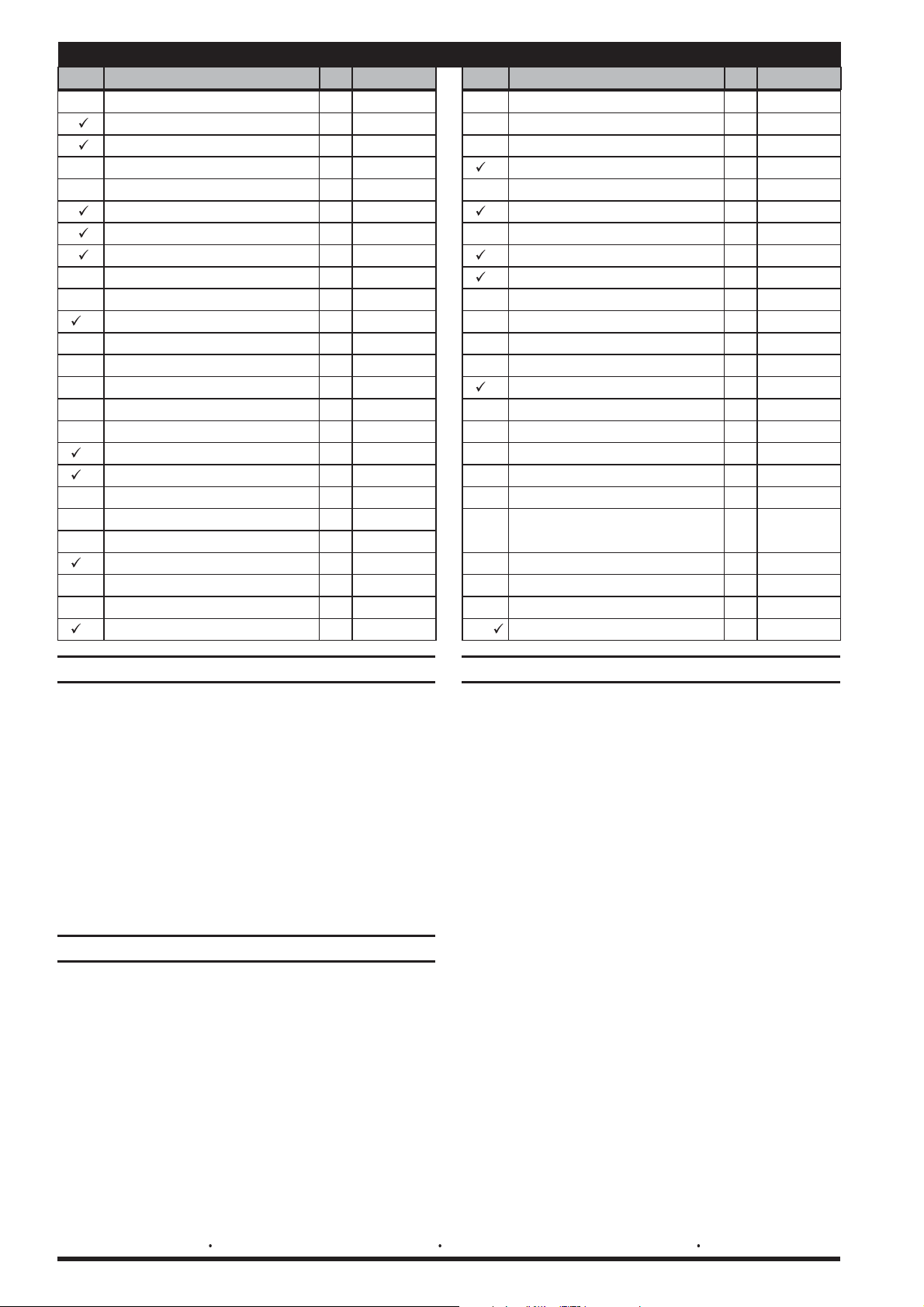
PARTS LIST / 67314-B
Item Description
2 “O” Ring
(1/4" - 28)
3 Nut
4a Spool (1) 94551
4b Sleeve (1) 94552
(0.3750” diameter)
5 Ball
7 “O” Ring
9 Cylinder Head (1) 95866
10 “O” Ring
11 Sleeve Washer (1) 94553
12 Retaining Ring (1) Y147-18
13 “O” Ring
21 “O” Ring
24 “O” Ring
(size)
(3/32” x 1-3/16” o.d.)
(3/32” x 11/16” o.d.)
(3/32” x 3-7/16” o.d.)
(3/32” x 1-3/4” o.d.)
(1/16” x 2-1/4” o.d.)
(3/32” x 1-7/8” o.d.)
(Qty) Part No. Item Description
(1) Y330-120
(3) 94794
(2) Y16-112
(2) Y330-112
(2) Y330-152
(3) Y330-129
(1) Y325-34
(1) Y330-131
(size)
94549)1(gulP poT1
11669)2(gnirpS6
01669)2(gulP pirT8
96859)1(wercS notsiP41
07859)1(notsiP51
17859)1(gniR raeW61
27859)1(laeS71
62669)1(doR pirT81
72669)2(rehsaW pirT91
85549)1(gnirpS pirT02
37859)1(doR notsiP22
76859)1(rednilyC32
25 Piston Rod Adapter (1) 95875
27 Plug
28 Polypack Rod Seal (1) 95903
32 “O” Ring
34 Hydraulic Tube (1) 94563
35 Washer
36 Hex Cap Screw
37 Nut
38 Spring Follower (2) 96609
39 Pipe Plug
40 Pipe Plug
41 Screw
43 Cap Screw
44 Swivel Union
45 Retaining Ring (1) Y145-4
(1/4 - 18 N.P.T.F.)
(1/16” x 5/8” o.d.)
(49/64” i.d. x 1-1/4” o.d. x 1/16”)
(3/4” - 16 x 11”)
(3/4” - 16)
(1/2 - 14 N.P.T.)
(3/4 - 14 N.P.T.)
(1/4” - 14 x 1/2”)
(3/8” - 24 x 1-1/2”)
14 N.P.S.M. female)
Temperature Label
Included in Service Kit 637450
(3/4 - 14 N.P.T.F. - 1 male x 3/4 -
(not shown)
(Qty) Part No.
86859)1(esaB rotoM62
(1) Y227-3-L
40959)1(gnihsuB92
50959)1(repiW03
47859)1(reniateR laeS13
(2) Y330-14
41-811Y)2(gniR pu-kcaB33
(3) F15-9-C
(3) 95876
(3) 96272
(1) Y17-13-C
(1) Y17-14-C
(1) Y334-104-C
40039)1(guL dnuorG24
(6) Y157-64
(1) 75367
(1) 94574
INSTALLATION
Use only flexible tubing for inlet and outlet porting to hydraulic source to prevent wear of components.
Be sure return lines are sized larger than supply lines and
similarly pressure rated.
Inspect the system hoses frequently for wear or damage and,
if necessary, replace them immediately. Never plug hose
leaks with your nger, tape or any similar devices.
Do not use PTFE tape on the inlet and outlet port
y
fittings. Loctite® 571 pipe thread sealant or equivalent is the recommended sealant.
Tighten the inlet and outlet fittings to 50 - 70 ft lbs
y
(67.8 - 94.9 Nm).
SERVICE
NOTE: The 67314-B hydraulic motor will contain about one
pint of hydraulic uid. Drain this uid before attempting any
disassembly.
NOTE: Do not disassemble this motor except in a clean area.
Any dust or dirt contamination of this assembly will shorten
the service life of this motor and other system components.
NOTE: All power supply pumps should have a ten micron
lter on the return line and a 100 mesh lter on the inlet. Failure to maintain lters will shorten service life of this motor
and other system components.
TROUBLE SHOOTING
If the pump will not cycle or will not deliver material.
Be certain to check for non-pump problems, including
y
kinked, restrictive or plugged inlet / outlet hose or dispensing device. Depressurize the pump system and clean
out any obstructions in the inlet / outlet material lines.
Check all seals, including track gaskets.
y
Check direction of “U” cup lips.
y
Motor is running beyond recommended temperature operating conditions.
Hydraulic oil cooling system is not working.
y
Piston seals are worn, replace seals.
y
Leakage from weep hole in retainer.
Detection of rod seal wear, when the amount this ex-
y
ceeds is 5 cc / day, replace wiper and rod seal.
Preventive maintenance issue, consult the factory for rec-
y
ommendations.
Motor stalls at fully retracted or extended position.
Insufficient pressure to motor (65 p.s.i. / 4.5 bar mini-
y
mum).
Springs need to be replaced.
y
Valve is damaged, service hydraulic motor.
y
ARO® is a registered trademark Ingersoll-Rand Company Loctite® is a registered trademark of Henkel Loctite Corporation
Page 2 of 4 67314-B (en)
Page 3

PARTS LIST / 67314-B
1
3a
)
7
8 5
) 37
35
44
40
13
12
2
4a
38
6
39
9
4b
11
10
23
)
19
24
25
45
20
3b (
21
22
32
33
34
4241
14
16
15
17
18
(
10
Figure 2
28
29
31
30
43
36
33
32
26
27
) TORQUE REQUIREMENTS (
NOTE: DO NOT OVERTIGHTEN FASTENERS.
(3a, 3b) 90 - 110 in. lbs (10.2 - 12.4 Nm).
(14) 100 - 120 ft lbs (135.6 - 162.7 Nm).
(25) 100 - 120 ft lbs (135.6 - 162.7 Nm).
(37) 44 - 56 ft lbs (59.7 - 75.9 Nm).
LUBRICATION / SEALANTS
Apply Loctite 571 pipe thread sealant or equivalent.
Apply Loctite 572 sealant to threads.
Apply Loctite 271 to the middle 7 - 9 threads.
See reassembly instruction step #5.
67314-B (en) Page 3 of 4
Page 4

DISASSEMBLY
REASSEMBLY
All threads are right hand. Refer to gure 2, page 3. These
procedures are for the installation of repair kit parts.
Disconnect power supply and relieve all system pressure
prior to servicing. Carefully remove the parts, inspect parts
for damage, nicks or excessive wear and determine if any
parts will need replacement.
1.
Remove (1) top plug and remove (2) “O” ring.
2.
Remove (8) trip plug and remove (5) ball, (38) spring follower, (6) spring and (7) “O” ring.
3.
Move piston rod to the fully retracted position and pull
(4a) spool out of (4b) sleeve through the top.
.
4
Using the ats on (18) trip rod to hold, remove and discard (3a) nut. DO NOT RE-USE. The trip rod wrench ats
are only accessible through the port holes that retain the
(8) trip plug. This will require a narrow width open-end
wrench.
NOTE: Be very careful when removing the spool from
the valve. The nish of this part is critical for proper
motor performance. Any nicks, scratches or dirt may
damage the set.
5. Remove (43) cap screws.
6. Slide (31) seal retainer, (29) bushing and (30) wiper off
(22) piston rod and (25) piston rod adapter.
7. Remove (37) tie rod nus and (35) washers.
8. Clamp (9) cylinder head and remove (26) motor base by
tapping with a soft hammer, then remove (10) “O” ring
and (28) polypack rod seal.
9. Remove (34) hydraulic tube from (9) cylinder head and
remove (32) “O” rings and (33) back-up rings.
10. Remove (22) piston rod assembly and (23) cylinder from
(9) cylinder head and remove (10) “O” ring.
11. Separate (22, 17, 21, 16, 15, 14) piston rod assembly from
(23) cylinder.
12. Remove (17) seal and (16) wear ring from (15) piston.
13. If further disassembly is required, such as removal of (22)
piston rod, (4) valve spool assembly, or (45, 20, 19, 18)
shifter assembly, see next section. (Order “O” rings separately.)
Removal of (4) sleeve and spool assembly.
14. Remove (12) retaining ring and (11) sleeve washer from
(9) cylinder head. Push the (4b) sleeve carefully down
through the (9) cylinder head using a soft faced tool.
NOTE: The finish of the upper face of the sleeve is
critical for intended operation. Any nicks or scratches
may damage the entire (4) set.
Removal of (22) piston rod.
15. Place the (22, 21, 17, 16, 15, 14) piston rod assembly in
a vertical position with the (25) piston rod adapter in a
heavy vise.
NOTE: Never clamp on the (22) piston rod.
16. Grip the ats on the (14) piston screw and unthread.
17. Remove (21) “O” ring from (22) piston rod.
18. Remove the (18, 19, 20, 45) trip rod assembly.
19. Using the ats on the (18) rod, remove and discard the
two (3b) nuts. DO NOT RE-USE.
Thoroughly clean and lubricate all seals. Replace all soft
parts with new ones included in the repair kit.
1.
Install (28) rod seal and (10) “O” ring into (26) motor base.
2.
Install (30) wiper into (31) seal retainer and slip in (29)
bushing.
3.
Slide (25, 22) piston rod assembly into (26) motor base
and retainer assembly from step #2 above.
4.
Insert (21) “O” ring onto (22) piston rod and place (15)
piston on it.
5.
Assemble (45) retaining ring, (19) trip washer, (20) trip
spring and (19) trip washer to (18) trip rod, securing with
one (3b) nut. NOTE: Orient the two (3b) nuts such that
the anges are facing each other. NOTE: (3b) nut to be
hand tight. While holding (18) trip rod on ats, assemble
(3b) nut to (18) trip rod and tighten to 90 - 110 in. lbs
(10.2 - 12.4 Nm).
6.
Place (18, 19, 20, 45, 3b) shifter assembly into (22) piston
rod and thread (14) piston screw into (22) piston rod.
7.
Torque (14) piston screw to 100 - 120 ft lbs (135.6 - 162.7
Nm) with (25) piston rod adapter in a heavy vise.
8.
Put (17) seal and (16) wear ring on (15) piston.
9.
Push (22) piston rod to fully extended position and place
(23) cylinder over the piston assembly.
10.
Seat the (23) cylinder onto the motor base. NOTE: Petroleum jelly is recommended for ease of assembly on all “O”
rings and inside the cylinder.
11.
Replace the three (13) “O” rings on (4b) valve sleeve.
12.
Push (4b) valve sleeve / spool set straight into (9) cylinder head.
13.
Place (11) sleeve washer behind (4b) valve sleeve and
retain this with (12) retaining ring.
14.
Put two (33) back-up rings and two (32) “O” rings onto
(34) hydraulic tube with back-up rings on the hydraulic
tube rst.
15.
Push tube assembly (34, 33, 32) into (26) motor base.
16.
Place (10) “O” ring on (9) cylinder head, lower (9) cylinder
head onto the (23) cylinder and (34) hydraulic tube with
the (18) trip rod through the center of the valve.
17.
Feed (36) bolts through (26) motor base and apply (35)
washers and (37) nuts to the bolts. Tighten fasteners alternately and apply 44 - 56 ft lbs (59.7 - 75.9 Nm). NOTE:
Must alternately rundown fasteners to prevent cutting
the (10) “O” rings.
18.
Assemble (31) seal retainer, retaining with six (43) cap
screws.
19.
Move piston to the retracted position.
20.
Pull (18) trip rod through the head and place the (4a)
spool on the trip rod. Using the (3a) nut and the trip rod
flats, tighten the (3a) nut to 90 - 110 in. lbs (10.2 - 12.4
Nm).
21.
Carefully push the spool / trip rod into the sleeve, creating the (4) valve.
22.
Place (2) “O” ring on (1) top plug and tighten in (9) cylinder head.
23.
Place (7) “O” ring on (8) trip plug. Place (5) ball in (9) cylinder head and (6) spring and (38) spring follower in (8)
trip plug.
24.
Thread the (8) trip plug into the (9) cylinder head.
PN 97999-1220
Page 4 of 4 67314-B (en)
 Loading...