

Page 1
OPERATOR’S MANUAL
INCLUDING: OPERATION, INSTALLATION & MAINTENANCE
SOLENOID ACTUATED PUMP KITS
FOR DIAPHRAGM PUMPS
67165-X
67166-X
67277-X
RELEASED: 3-6-98
REVISED: 3-7-06
(REV. G)
SOLENOID ACTUATED PUMP KITS
67165-( ) for 3/8" and 1/2" diaphragm pumps, as follows:
66605X-X, PD03P-X-X, PD05P-X-X, PD05P-X-X-B, PD05R-X-X-B
and PM05P-X-X-A02.
67166-( ) for 1", 1-1/2" and 2" non-metallic diaphragm pumps as follows:
6661AX-X-C, 6661BX-X-C, 6661TX-X-C, 6661UX-X-C, 6662AX-X-C
and 6662BX-X-C.
67166-( ) for 1" and 1-1/2" metallic diaphragm pumps as follows:
66610X-X-C, 66611X-X-C, 66612X-X-C, 66613X-X-C, 66615X-X-C,
66616X-X-C, 66617X-X-C and 66618X-X-C.
67277-( ) for 2" and 3" metallic diaphragm pumps as follows:
PD20A-X-X, PF20A-X-X, PM20A-X-X-A02, PD30A-X-X-B and
PM30A-X-X-B02.
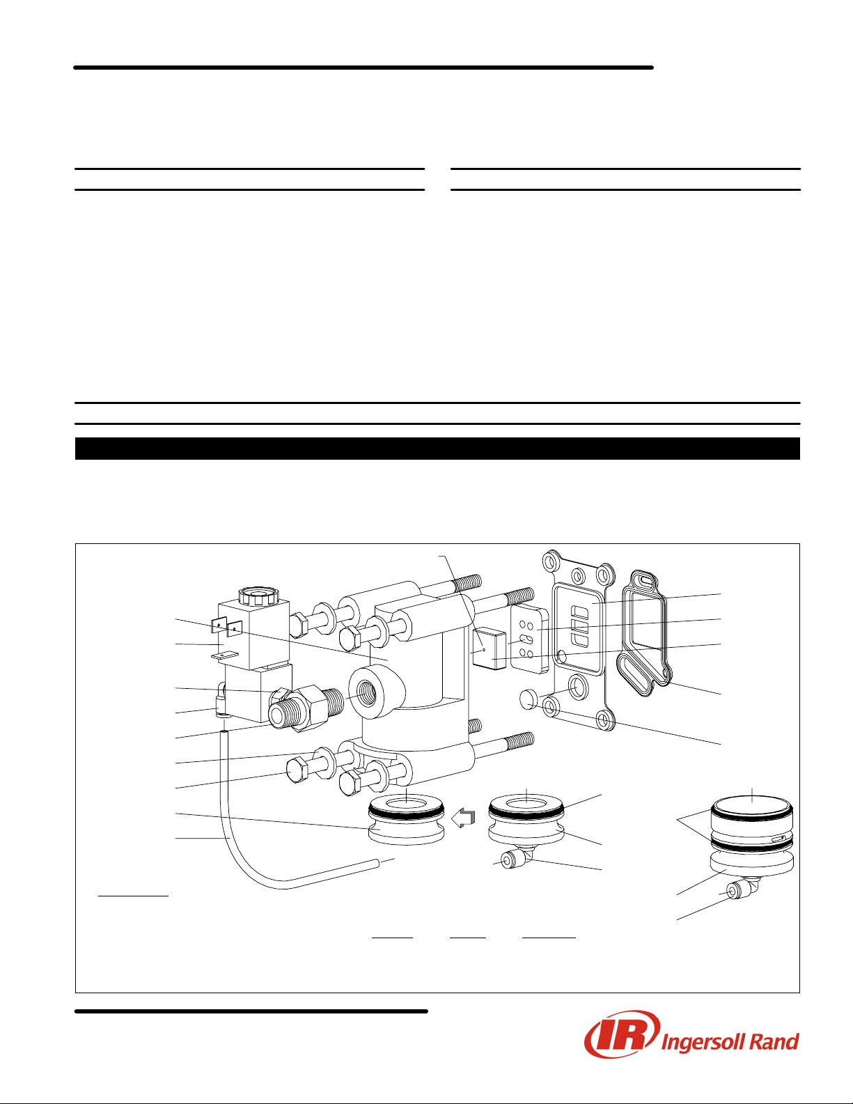
67165-( ) SOLENOID KIT INSTALLATION
3/8” AND 1/2” DIAPHRAGM PUMPS
Refer to figure 1.
1. Remove (134) bolts from the major valve and remove (135) valve
block.
2. Remove (136) plug and replace with 93909 or 96462 plug.
3. Place 94640 plug in pilot hole.
Identification dot this side.
GENERAL DESCRIPTION
ARO solenoid actuated diaphragm pump kits allow the cycle rate of the
pump to be controlled electronically. When the solenoid is energized, the
pump strokes and dispenses the fluid in one chamber. When the solenoid is de-energized, the pump strokes in the opposite direction, dispensing the fluid in the other chamber.
By providing continuous ON - OFF signals to the solenoid, the fluid
transfer rate may be increased or decreased remotely.
Some parts of the pump must be replaced with those included in these
kits to enable solenoid actuation.
4. Attach (135) valve block to (101) motor body, using (133) washers
and (134) bolts. NOTE: Torque to 15 - 20 in. lbs (1.7 - 2.3 Nm).
5. Thread CAT33P-( )-( ) valve assembly into air supply port.
6. Connect CAT33P-( )-( ) valve with 93909 plug, using 94981-XXX-X
tube.
135
~ Valve
(see table)
~ 676
~ 59756-4
~ 90351
133
. 134
136
~ 94981-XXX-X
(5" long) g
NOT SHOWN
CHW Connector
k Assemble with 2 identification dots toward (132) gasket.
. Torque to 15 - 20 in. lbs (1.7 - 2.3 Nm).
~ Supplied with 67165-( ) Kit.
Z See page 4 for coil options.
g 94981-XXX-X Bulk Tubing (100’ long).
MODEL VALVE VOLTAGE
67165-1 CAT33P-024-D 24 VDC
67165-2 CAT33P-120-A 120 VAC
67165-3 CAT33P-000-N No Coil Z
132
141 k
140
96214-2 ~
94640 ~
Y325-125 ~
~ Y325-29
93909 ~
59756-4 ~
~ 96462
~ 59756-4
Figure 1
INGERSOLL RAND COMPANY LTD
P.O. BOX 151 D ONE ARO CENTER D BRYAN, OHIO 43506-0151
& (800) 276-4658 D FAX (800) 266-7016
E2006 CCN 99711780
Page 2
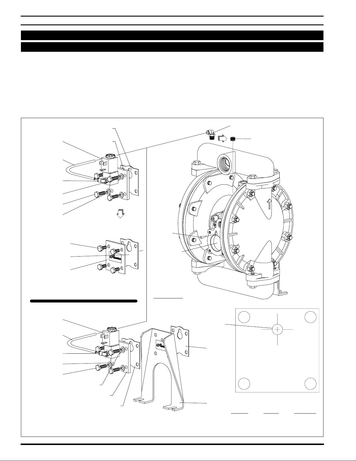
67166-( ) SOLENOID KIT INSTALLATION
1”, 1-1/2” AND 2” NON-METALLIC DIAPHRAGM PUMPS
1” AND 1-1/2” METALLIC DIAPHRAGM PUMPS
Refer to figure 2.
1. Remove (105) bolts from air inlet end of (101) motor body and remove (107) leg / plate and (108) gasket.
2. Place 94641 taper plug in pilot hole of (101) motor body.
3. Replace (128) pipe plug on (101) motor body with 59756-4 fitting.
For 1" Metallic models only:
4. Drill a 1/4" (0.250) hole in (107) leg, using the template below.
5. Attach (108) gasket, modified (107) leg, 92878 gasket and CAT33P-(
)-( ) valve to (101) motor body, using Y6-44-C bolts and Y14-416-T
washers. NOTE: Torque to 40 - 50 in. lbs (4.5 - 5.6 Nm).
6. Connect CAT33P-( )-( ) valve with 59756-4 fitting, using
94981-XXX-X tube.
For all others:
4. Attach (108) gasket and CAT33P-( )-( ) valve to (101) motor body,
using Y6-44-C bolts and Y14-416-T washers. NOTE: Torque to 40 50 in. lbs (4.5 - 5.6 Nm).
5. Connect CAT33P-( )-( ) valve with 59756-4 fitting, using
94981-XXX-X tube.
108
~ Valve
(see table below)
~ 94981-XXX-X
(6-1/16" long) g
~ 59756-4
~ 676
~ . Y6-44-C (4)
~ Y14-416-T (4)
~ 93911
105
108
107
1", 1-1/2" and 2" Non-Metallic and 1-1/2"
Metallic models (above heavy line)
1" Metallic models (below heavy line)
~ 94641
NOT SHOWN
CHW Connector
59756-4 ~
(Located on bottom of 1-1/2"
128
and 2" motor bodies.)
TOP
~ Valve
(see table below)
~ 94981-XXX-X
(6-1/16" long) g
~ 59756-4
~ Y14-416-T (4)
~ . Y6-44-C (4)
~ 676
. Torque to 40 - 50 in. lbs (4.5 - 5.6 Nm).
~ Supplied with 67166-( ) Kit.
Z See page 4 for coil options.
g 94981-XXX-X Bulk Tubing (100’ long).
~ 93911
~ 92878
Figure 2
1/4" Dia.
108
TEMPLATE
107
MODEL VALVE VOLTAGE
67166-1 CAT33P-024-D 24 VDC
67166-2 CAT33P-120-A 120 VAC
67166-3 CAT33P-000-N No Coil Z
67165-XPage 2 of 4
Page 3

67277-( ) SOLENOID KIT INSTALLATION
2” & 3” METALLIC DIAPHRAGM PUMPS
Refer to figure 3.
1. Remove (134) screws and (133) washers, and remove (135) valve
block and components from (101) center body.
. Torque to 40 - 50 in. lbs (4.5 - 5.6 Nm).
Z See page 4 for coil options.
~ Included in 67277-( ) Kit.
101
~ 29670 Ball
133
2. Attach 67277-( ) solenoid kit assembly to (101) center body, using
(134) screws and (133) washers. NOTE: Torque screws to 40 - 50 in.
lbs (4.5 - 5.6 Nm).
67277-( )
67277-( ) PARTS LIST
114104 O" Ring (1.5 mm x 14.5 mm o.d.)
Y325-126 O" Ring (2) (3/32" x 1-9/16" o.d.)
92011 Piston
Y186-51 U" Cup (3/16" x 1-3/8" o.d.)
94032-1 Valve Block
. 134
135
43
Figure 3
119380 Coil Nut
116218-( ) Coil (see table)
114102 Valve System
114103 O" Ring (1.5 mm x 5.5 mm o.d.)
Y147-16-C Retaining Ring (1.804" o.d.)
94728 Solenoid Plug
92005 Spool
92876 Spacer (4)
Y325-214 O" Ring (5) (1/8" x 1-1/4" o.d.)
NOT SHOWN
CHW Connector
Y16-203 Ball (2) (3/32" dia, press flush w/94032-1)
96728647 Cap Screw (2) (M3 - .5 x 18)
MODEL VOLTAGE COIL
67277-1 24 VDC 116218-39
67277-2 120 VAC 116218-33
67277-3 No Coil Z
Y325-126 O" Ring (6) (3/32" x 1-9/16" o.d.)
92877 Washer (5)
94027 Spacer
94034 Inlet Plug
Figure 4
Page 3 of 467165-X
Page 4

DISPLACEMENT PER CYCLE
Specific Gravity = 1.000
Models Gallons Ounces in.# cc Liters Grams Kg
3/8" Non-Metallic − PD03P-X-X 0.022 2.815 5.082 83 0.083 83 0.083
1/2" Non-Metallic Duck Bill − 66605X-0XX 0.032 4.095 7.392 121 0.121 121 0.121
1/2" − PD05P-X-X-B, PD05R-X-X-B 0.039 4.991 9.009 148 0.148 148 0.148
1/2" − 66605X-X, PD05P-X-X, PM05P-X-X-A02 0.040 5.119 9.240 151 0.151 151 0.151
1" Non-Metallic − 6661AX-X-C, 6661BX-X-C 0.170 21.756 39.270 643 0.643 643 0.643
1" Metallic − 66610X-X-C, 66611X-X-C, 66612X-X-C,
66613X-X-C
1-1/2" Non-Metallic − 6661TX-X-C, 6661UX-X-C 0.670 85.743 154.770 2536 2.536 2534 2.534
1-1/2" Metallic − 66615X-X-C, 66616X-X-C, 66617X-
X-C, 66618X-X-C
2" Non-Metallic − 6662AX-X-C, 6662BX-X-C 0.720 92.141 166.320 2725 2.725 2723 2.723
2" Metallic − PD20A-X-X, PF20A-X-X, PM20A-X-X-A02 1.400 179.164 323.400 5299 5.299 5296 5.296
3" Metallic − PD30A-X-X-B, PM30A-X-X-B02 2.800 358.327 646.800 10,598 10.598 10,591 10.591
2 strokes per complete cycle - 1" metallic will displace 0.080 gallons per stroke.
0.160 20.476 36.960 606 0.606 605 0.605
0.640 81.903 147.840 2422 2.422 2421 2.421
COIL OPTIONS
Coil Number 50 / 60 Hz DC
116218-31 12
116218-33 120
116218-35 240
116218-37 5
116218-38 24 12
116218-39 48 24
PN 97999-760
67165-XPage 4 of 4
 Loading...