

Ingersoll-Rand 651533-X Operator's Manual
OPERAT
MANUAL
DEL OPERARIO
OR’S MANUAL
MANUEL DE L’UTILISATEUR
INCLUDING: OPERA
INCLUYE: FUNCIONAMIENT
COMPREND: FONCTIONNEMENT
INCLUDE FORM 772Ć2 (97999Ć540)
INCLUYE FORMULARIO 772Ć2
COMPREND FORM 772Ć2
PISTOLA PUL
TION, INST
ALLA
O, INST
TION & MAINTENANCE
ALACIÓN & MANTENIMIENT
, INST
ALLA
AIRLESS P
VERIZADORA SIN AIRE P
PIST
OLET À PEINDRE SANS AIR (SANS BUSE DE PUL
TION & ENTRETIEN
651533 & 651533-1
AINT SPRA
ARA PINTURA (SIN BOQUILLA PULVERIZADORA)
RELEASED
REVISED / REVISADO / REVISE:
(REV
O
/ LIBERADO / DECHARGE:
. C)
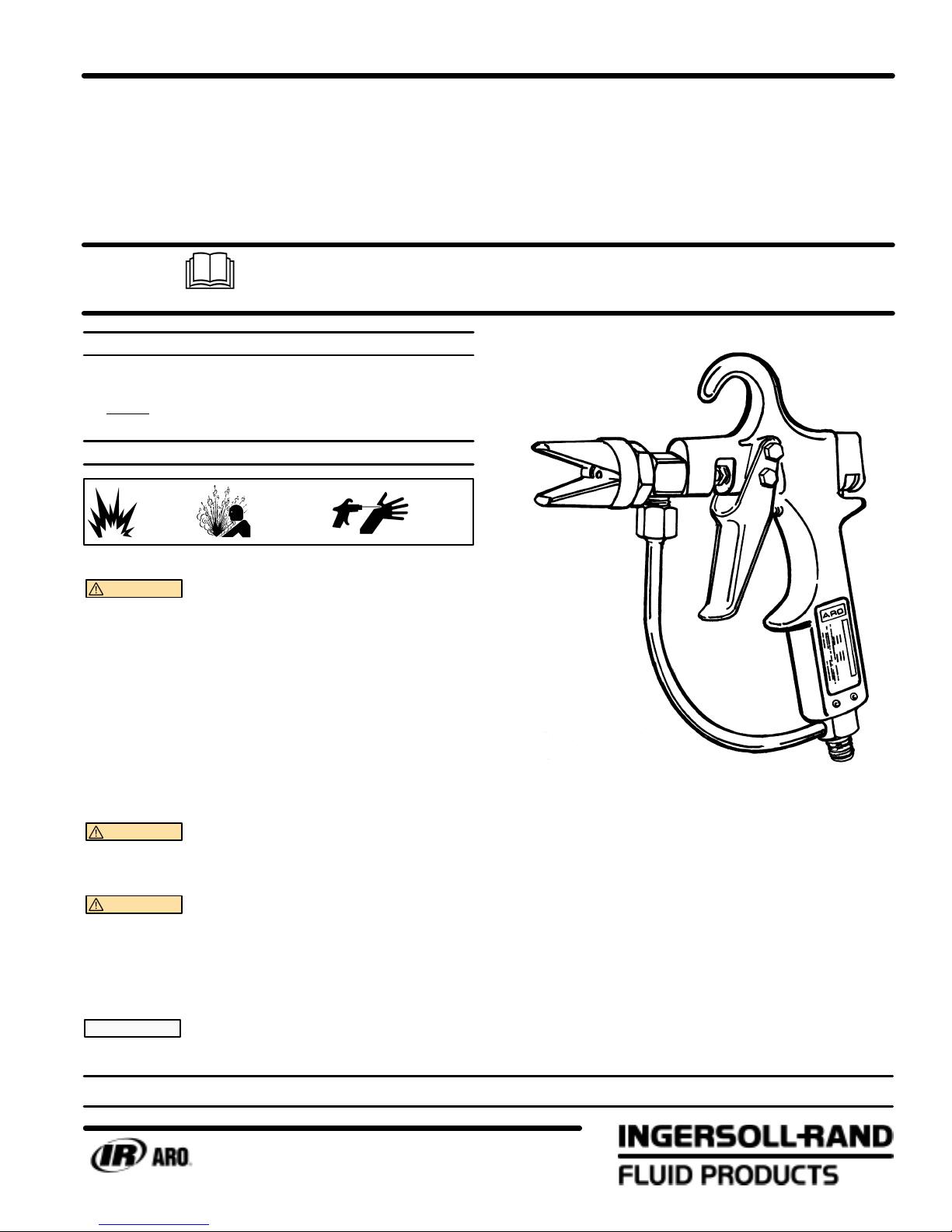
Y GUN (WITHOUT SPRAY TIP)
VÉRISATION)
651533-X
9-16-80
7-14-00
READ THIS MANUAL CAREFULL
OPERA
It
is the responsibility of the employer to place this information in the hands of the operator
SER
VICE KITS
TING OR SER
• Use only genuine AROR replacement parts to assure compatible
pressure rating and longest service life.
• 637103 for repair of spray gun.
OPERATING
STATIC
SPARK
WARNING
in severe injuryor death. Ground pump and pumping system.
AND SAFETY PRECAUTIONS
HAZARDOUS
PRESSURE
STATIC SPARK. Can cause explosion resulting
INJECTION
HAZARD
• The pumping system and object being sprayed must be
grounded whenit ispumping, flushing, recirculatingor sprayĆ
ing flammable materials such as paints, solvents, lacquers,
etc. or used in a location where surrounding atmosphere is
conducive to spontaneous combustion. Ground the dispensĆ
ing valveor device,containers, hoses andany objectto which
material is being pumped.
• Use hoses incorporating a static wire.
• Use proper ventilation.
• Keep inflammables away from heat, open flames and sparks.
• Keep containers closed when not in use.
WARNING
injury orproperty damage. Do not service or clean while presĆ
surized.
WARNING
flesh can cause severe injury or death. If an injection occurs
immediately contact a doctor.
HAZARDOUS PRESSURE. Can result in serious
INJECTION HAZARD. Any material injected into
• Do not grab front end of dispensing device.
• Do not aim dispensing device at anyone or any part of the
body.
NOTICE Liquid pressureat the outletofgun may bemany
times the air inlet gauge pressure of air operated pumps.
Y BEFORE INST
VICING THIS EQUIPMENT
. Keep for future reference.
Safety precautions should be taken while operating or servicing
high pressure equipment.
ALLING,
.
• CHECK hoses for weak or worn condition before each use,
and tighten all fluid connections securely.
• DO NOT alter equipment in any manner whatsoever.
• DO NOT exceed the maximum working pressure of any comĆ
ponent in the system (including but not limited tospray guns,
hose, hose connections, heaters and pumps).
• DISCONNECT pump power source and RELIEVE allpressure
from system when not in use.
• When gun is not in use, always set safety lock in closed posiĆ
tion.
INGERSOLLĆRAND COMPANY shall not be liable for any conseĆ
quential damages as a result of misuse, misapplication, abuse,
etc. of this equipment.
MAXIMUM WORKING PRESSURE 5000 P.S.I. (345 BAR)
INGERSOLL-RAND COMPANY
P.O. BOX 151 D ONE ARO CENTER D BRYAN, OHIO 43506Ć0151
&
(419) 636-4242 D F
AX (419) 633-1674
E2000 D PRINTED IN U.S.A.

MAINTENANCE
DISASSEMBLY
With proper care, this unitwill give long reliable service.To maintainthis
performance it shouldbe flushed out with solvent immediately following
each spray period.
CAUTION Always disconnect pump power source and reĆ
lease all pressure before disassembly or removal of any part.
FOR CLEANING: Use solvent with highest possible flash point,
that is compatible to material being used.
1. ShutĆoff air pressure to pump and relieve liquid pressure in system
through manual relief valve at outlet filter on those models
equipped, or trigger gun making sure pressure is relieved. Never
attempt to force paint backward from gun through hose to pump
and paint container.
2. Place gun safety lock in closed position and remove spray tip from
gun. Place tip in small container of solvent for soaking and final
cleaning. Use soft bristle brush to remove any paint collection on
tip. If tip orifice isclogged, remove obstruction byusing air blow gun
applied to outlet of orifice at front of tip and blowing back through
rear of tip, if obstruction will not blow out, use cleaning wire, toothĆ
pick or brush bristle to dislodge. NEVER ATTEMPT TO CLEAN
TIP WHILE IT IS ATTACHED TO SPRAY GUN.
3. Remove gunfrom hose and cleanexterior with suitable solventand
brush. Allow gun to soak in solvent for a short time if necessary to
soften accumulation. After cleaning, wipe exterior of gun with dry
cloth. (NOTE: Interior of gun has not yet been cleaned).
4. Remove pump from paint container and place pump inlet into conĆ
tainer of suitable clean solvent.
5. Direct open end of hose into paint container and start pump by apĆ
plying only sufficient air pressure to cycle pump slowly and to force
paint frompump and hose into groundedpaint container.When solĆ
vent begins to flow from hose, switch hose to grounded solvent conĆ
tainer, increase air pressure to pump allowing solvent to circulate
through pump, hose and back to container for approximately one
minute or until examination indicates hose and system are clean.
6. Whenever 60530 inline swivel filter is being used, remove from
hose and gun, disassemble and clean.
7. ShutĆoff air pressure to pump and assemble gun to end of hose.
8. Direct end gun (without tip) into top of grounded (bonding recomĆ
mended) solvent container and release safety lock on gun so trigĆ
ger can be retracted.
9. Start pump with gun trigger retracted, increase air pressure until
sufficient pressureisobtained to cause pump tocycleapproximateĆ
ly 25 cycles per minute. Purge gun approximately oneminute while
intermittently operating trigger. Adjust packing gland if necessary to
prevent leakage.
10. ShutĆoff air pressure to pump and pull gun trigger to relieve presĆ
sure in system while gun is still directed into grounded solvent conĆ
tainer.
11. Place safety lock on gun inclosedpositionandreassemblecleaned
spray tip to gun, wipe all exterior surfaces clean.
12. Disconnect pump from power source.
SERVICE
1. Disconnect air line from pump and relieve material line pressure by
pulling (22) trigger.
2. Disconnect material line from gun.
3. Unscrew the (1) capand guard assemblyand remove the (2)washĆ
er and spray tip.
4. Loosen the (13) collet nut.
5. Loosen the (19) set screw. Disconnect and remove the (21) inlet
tube brazing assembly by loosening the tube nut and rotating the
tube assembly 90_ to either side of the (20) handle.
6. Unscrew the (9) spray gun body and adapter assembly from the
(20) handle.
7. Remove the (3) screw, (8) washer and (12) retaining screw from (9)
spray gun body and adapter assembly.
8. Remove the (7) ball and stem assembly and the (10) packing and
(11) flat packing fromthe (9) spraygun body and adapter assembly.
For normalcleaning orservice, parts(14), (15),(16), (17), (18), (22),
(23), (24), (25), (26), (27) and (28) need not be removed.
REASSEMBLY
1. Insert the (7) ball and stem assembly into the (9) spray gun body
and adapter assembly.
2. Carefully slip the two (10) packings and two (11) flat packings inthe
order shown in the diagram over the wire of the (7) ball and stem
assembly.
3. Slide the (12) retaining screw onto the (7) ball and stem assembly
and push the packings into the (9) spray gun body and adapter asĆ
sembly. Tighten (12) retaining screw hand tight.
4. Install the (8) washer on the (3) screw and screw the assembly into
(9) spraygun body and adapter assembly hand tight. Then back off
screw 3/4 turn.
5. Push the (7)ball and stem assembly forwarduntilitseatson the ball
seat of the (3) screw and tighten (12) retaining screw.
6. Screw the (9) spray gun body and adapter assembly into the (20)
handle. Be sure the wire of the (7) ball and stem assembly enters
the hole in the (13) collet nut. Back off the (9) spray gun body and
adapter assembly until material inlet faces down. Tighten (19) set
screw.
7. Being sure the ball is still seated in the ball seat, retighten the (13)
collet nut.
8. Tighten the (3) screw.
9. Replace the (21) inlet tube brazing assembly into the (20) handle
and (9) spray gun body and adapter assembly.
10. Check safety operation byrotating the (25) knob tothesafeposition
and pull the (22) trigger. If movement of the (7) ball and stem asĆ
sembly is noted, adjust the gun as follows. With the safety off and
the ball seated on the ball seat, hold the trigger and loosen the (13)
collet nut. Pull the trigger back slightly and retighten the (13) collet
nut. Recheck safety operation and readjust if necessary.
11. Insert the spray tip and (2) washer in the (1) capand guard assemĆ
bly and screw cap on (9) spray gun body and adapter assembly.
If material leakage occurs around the (12) retaining screw, the (10)
packing and the (11) flat packing have perhaps become worn. Tighten
the (12) retaining screw and if this doesn't stop the leakage replace the
packing.
If material leakage occurs at the spray tip of the gun, check for dirt or
foreign matter which may prevent the (7) ball and stem assembly from
seating properly.
PAGE2OF8
651533ĆX
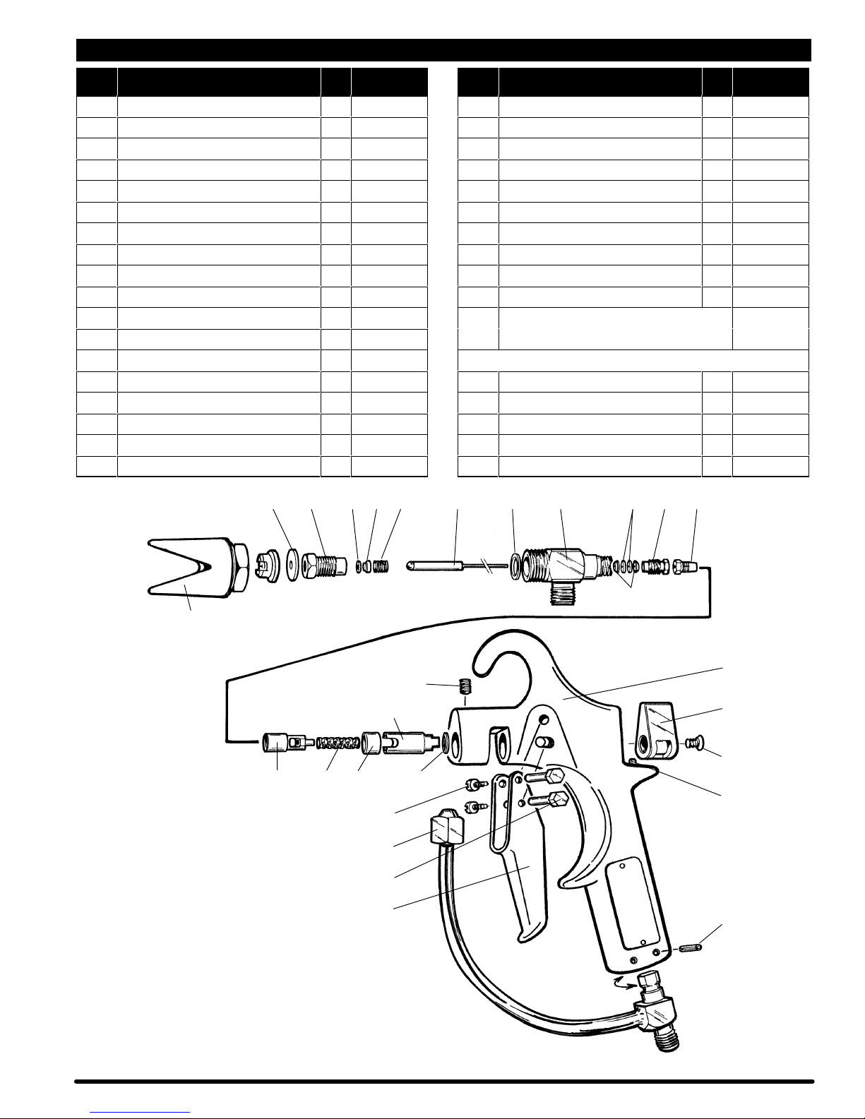
PARTS LIST / 651533-X AIRLESS GUN
ITEM DESCRIPTION (Size in inches)
QTY
PART NO. ITEM DESCRIPTION (Size in inches)
1 Cap & Guard Assembly (1) 66504
n 2 Washer (1) 91181
3 Screw (1) 92426
4 Gasket (1) 92425
5 Ball Seat (1) 92424
6 Screw (1) 92427
n 7 Ball & Stem Assembly (1) 66597Ć1
n 8 Washer (1) 91180
9 Spray Gun Body & Adapter Asm (1) 66178
n 10 Packing (2) 91471
n 11 Flat Packing (2) 91472
n 12 Retaining Screw (1) 91473
n 13 Collet Nut (1) 91474
14 Collet Adapter (1) 91475
15 Spring (1) 92746
16 Sleeve (1) 91481
17 Safety Pin (1) 92432
18 Washer (1) 92434
QTY
PART NO.
19 Set Screw (1/4" Ć 20 x 3/8" long) (1) Y29Ć44
20 Handle (1) 92430
21 Inlet Tube Brazing Assembly (1) 66596
22 Trigger (1) 92429
23 Screw (2) 90962
24 Screw Retainer (2) 92433
25 Knob (1) 92431
26 Screw (#10 Ć 24 x 1/2" long) (1) Y61Ć107ĆC
27 Roll Pin (1/8" o.d. x 3/8" long) (1) Y178Ć35
28 Roll Pin (1/8" o.d. x 3/4" long) (2) Y178Ć41
n Parts in Service Kit / Componentes en el juego
de servicio / Pièces de la trousse d'entretien
Items not shown / Artículos que no se muestran / Composants non illustrés
637103
Allen Wrench (1/8") (1) Y106Ć3
Wrench (1) 99231
Packing (Extra / Supplément) (2) 91471
Flat Packing (Extra / Supplément) (2) 91472
Spray Tip (not included / no incluidos / non compris)
TCXXXX
23~ 456z 7891011 12 13 ~
1 (651533 only)
(solamente 651533)
(651533 seulement)
14 15 16
= Apply Loctite 271 to threads.
Aplique Loctite 271 a las roscas.
Appliquer du Loctite 271 sur les filets.
~ Apply Loctite Nickel AntiĆSieze to threads.
Aplique Loctite Níquel antiadhesión a las roscas.
Appliquer du Loctite Nickel AntiĆseize sur les filets.
= 23
21
24
22
17 s
20
19
25
26 =
18
27
28
z Apply 80 Ć 90 wt gear oil to threads.
Aplique a las roscas aceite de engranajes 80 Ć 90 wt.
Appliquer de l'huile d'engrenages 80 Ć 90 SAE aux filetages.
s Coat with Shell Darina EP 2 grease.
Cubra con grasa Shell Darina EP 2.
Enduire de graisse Shell Darina EP 2.
651533ĆX PAGE3OF8
 Loading...