

Ingersoll-Rand 2135TiMAX-AP, 2135QTiMAX, 2135QTiMAX-AP, 2135QTi-2MAX, 2135QTi-2MAX-AP Product Information
...
Air Impact Wrench
2135TiMAX Series
Product Information
45534062
Edition 4
July 2011
EN
Product Information
ES
Especicaciones del producto
FR
Spécications du produit
IT
Speciche prodotto
DE
Technische Produktdaten
NL
Productspecicaties
DA
Produktspecikationer
SV
Produktspecikationer
NO
Produktspesikasjoner
FI
Tuote-erittely
PT
Especicações do Produto
EL
Προδιαγραφές προϊόντος
Save These Instructions
SL
Specikacije izdelka
SK
Špecikácie produktu
CS
Specikace výrobku
ET
Toote spetsikatsioon
HU
A termék jellemzői
LT
Gaminio techniniai duomenys
LV
Ierices specikacijas
PL
Informacje Macje o Produkcie
BG
Информация за Продукта
RO
Informaţii Privind Produsul
RU
Технические характеристики изделия
ZH
产品信息
JA
製品仕様
KO
제품 상세
4
7
5
3
2
1
9
6
11
48h
48h
PMAX
9
8h
24h
8
10
1
3
2
5
6
7
9
10
11
(Dwg. 47132782)
IR # - NPT IR # - BS inch (mm) NPT IR # IR # IR # cm3IR # cm
C38341-810 C383D1-810 3/8 (10) 1/4 MSCF33 10P 105-1lb 4 105-1lb 4
2 45534062_ed4
3

EN
Product Safety Information
Intended Use:
These Air Impact Wrenches are designed to remove and install threaded fasteners.
For additional information refer to Air Impact Wrench Product Safety Information Manual
Form 04580916.
Manuals can be downloaded from www.ingersollrandproducts.com.
Power Management System
For models that include a power management system, the system allows operator reduction
of maximum output power in the forward direction. The power management system does not
aect the output power in the reverse direction.
To adjust the power, rotate the Power Regulator to the desired level indicator.
The power level indicators are for reference and DO NOT indicate a specic power. The power
output can be further reduced in forward or reverse by using the variable throttle.
Product Specications
Models Style
2135TiMAX
2135TiMAX-AP
2135Ti-2MAX
2135Ti-2MAX-AP
2135QTiMAX
2135QTiMAX-AP
2135QTi-2MAX
2135QTi-2MAX-AP
2135QPTiMAX
2135QPTiMAX-AP
2135PTiMAX
2135PTiMAX-AP
Pistol Square 1/2” 1,250
Pistol
Pistol Square 1/2” 1,250
Pistol
Pistol
Pistol
Drive
Type Size
Square
extended
Square
extended
Square
(Pin Retainer)
Square
(Pin Retainer)
Impacts
per
min.
1/2” x 2” 1,250
1/2” x 2” 1,250
1/2” 1,250
1/2” 1,250
Recommended
Torque Range
Forward
ft-lbs (Nm)
50-550 [600 Max.]
(68-746 [813 Max.])
50-550 [600 Max.]
(68-746 [813 Max.])
50-550 [600 Max.]
(68-746 [813 Max.])
50-550 [600 Max.]
(68-746 [813 Max.])
50-550 [600 Max.]
(68-746 [813 Max.])
50-550 [600 Max.]
(68-746 [813 Max.])
Reverse
ft-lbs (Nm)
650 [780 Max.]
(880 [1057 Max.])
650 [780 Max.]
(880 [1057 Max.])
650 [780 Max.]
(880 [1057 Max.])
650 [780 Max.]
(880 [1057 Max.])
650 [780 Max.]
(880 [1057 Max.])
650 [780 Max.]
(880 [1057 Max.])
45534062_ed4 EN-1

EN
Impacting Sound Level
dB(A)
Models
2135TiMAX
2135TiMAX-AP
2135Ti-2MAX
2135Ti-2MAX-AP
2135QTiMAX
2135QTiMAX-AP
2135QTi-2MAX
2135QTi-2MAX-AP
2135QPTiMAX
2135QPTiMAX-AP
2135PTiMAX
2135PTiMAX-AP
† KpA = 3dB measurement uncertainty
‡ KwA = 3dB measurement uncertainty
* K = Vibration measurement uncertainty
(ISO15744)
† Pressure
‡ Power (Lw) † Pressure (Lp) ‡ Power (Lw) Level *K
(Lp)
99.8 110.8 109.2 120.2 13.3 4.6
99.8 110.8 109.2 120.2 9.7 1.8
94.2 105.2 86.0 97.0 13.3 4.6
94.2 105.2 86.0 97.0 9.7 1.8
94.2 105.2 86.0 97.0 13.3 4.6
99.8 110.8 109.2 120.2 13.3 4.6
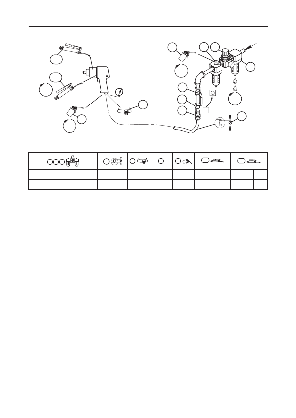
Installation and Lubrication
Size air supply line to ensure tool’s maximum operating pressure (PMAX) at tool inlet. Drain
condensate from valve(s) at low point(s) of piping, air lter and compressor tank daily. Install a
properly sized Safety Air Fuse upstream of hose and use an anti-whip device across any hose
coupling without internal shut-o, to prevent hose whipping if a hose fails or coupling disconnects. See drawing 47132782 and table on page 2. Maintenance frequency is shown in a circular
arrow and dened as h=hours, d=days, and m=months of actual use. Items identied as:
1. Air lter 7. Coupling
2. Regulator 8. Safety Air Fuse
3. Lubricator 9. Oil
4. Emergency shut-o valve 10. Grease - during assembly
5. Hose diameter 11. Grease - through tting
6. Thread size
Free Speed Sound Level dB(A)
(ISO15744)
Vibration (m/s²)
(ISO28927)
Parts and Maintenance
When the life of the tool has expired, it is recommended that the tool be disassembled,
degreased and parts be separated by material so that they can be recycled.
Original instructions are in English. Other languages are a translation of the original instructions.
Tool repair and maintenance should only be carried out by an authorized Service Center.
Refer all communications to the nearest Ingersoll Rand Oce or Distributor.
EN-2 45534062_ed4

Información de Seguridad Sobre el Producto
Uso Indicado:
Los aprietatuercas neumáticos de percusión están diseñados para extraer e instalar
adores roscados.
Para más información, consulte el Manual de información de seguridad de producto
04580916 Aprietatuercas neumático de percusión.
Los manuales pueden descargarse en www.ingersollrandproducts.com.
Gestión de la Potencia de Impacto
Para los modelos que incluyen un sistema de gestión de potencia, el sistema permite al
operador reducir la potencia de salida máxima de atornillado. El sistema de gestión de
potencia no afecta a la potencia de salida en aojado.
Para ajustar la potencia, gire el regulador de potencia al indicador de nivel deseado.
Los indicadores de nivel de potencia sirven de referencia y NO indican una potencia
exacta. La potencia disponible se puede reducir aún más en la dirección de atornillado o
aojado con el mando variable.
Especicaciones del Producto
Modelos Estilo
2135TiMAX
2135TiMAX-AP
2135Ti-2MAX
2135Ti-2MAX-AP
2135QTiMAX
2135QTiMAX-AP
2135QTi-2MAX
2135QTi-2MAX-AP
2135QPTiMAX
2135QPTiMAX-AP
2135PTiMAX
2135PTiMAX-AP
Accionamiento
Tipo Tamaño
Pistola Cuadrado 1/2” 1,250
Cuadrado
Pistola
Pistola Cuadrado 1/2” 1,250
Pistola
Pistola
(pasador de
retención)
Pistola
(pasador de
retención)
ampliado
Cuadrado
ampliado
Cuadrado
Cuadrado
1/2” x 2” 1,250
1/2” x 2” 1,250
1/2” 1,250
1/2” 1,250
Intervalo de par Recomendado
Impact
os por
Minuto
Avance
ft-lb (Nm)
50-550 [600 Max.]
(68-746 [813 Max.])
50-550 [600 Max.]
(68-746 [813 Max.])
50-550 [600 Max.]
(68-746 [813 Max.])
50-550 [600 Max.]
(68-746 [813 Max.])
50-550 [600 Max.]
(68-746 [813 Max.])
50-550 [600 Max.]
(68-746 [813 Max.])
Retroceso
ft-lb (Nm)
650 [780 Max.]
(880 [1057 Max.])
650 [780 Max.]
(880 [1057 Max.])
650 [780 Max.]
(880 [1057 Max.])
650 [780 Max.]
(880 [1057 Max.])
650 [780 Max.]
(880 [1057 Max.])
650 [780 Max.]
(880 [1057 Max.])
ES
45534062_ed4 ES-1

ES
Impacto
Nivel Sonoro dB(A)
Modelos
2135TiMAX
2135TiMAX-AP
2135Ti-2MAX
2135Ti-2MAX-AP
2135QTiMAX
2135QTiMAX-AP
2135QTi-2MAX
2135QTi-2MAX-AP
2135QPTiMAX
2135QPTiMAX-AP
2135PTiMAX
2135PTiMAX-AP
† KpA = 3dB de error * K = de error (Vibración)
‡ KwA = 3dB de error
(ISO15744)
† Presión
‡ Potencia (Lw) † Presión (Lp) ‡ Potencia (Lw) Nivel *K
(Lp)
99.8 110.8 109.2 120.2 13.3 4.6
99.8 110.8 109.2 120.2 9.7 1.8
94.2 105.2 86.0 97.0 13.3 4.6
94.2 105.2 86.0 97.0 9.7 1.8
94.2 105.2 86.0 97.0 13.3 4.6
99.8 110.8 109.2 120.2 13.3 4.6
Instalación y Lubricación
Diseñe la línea de suministro de aire para asegurar la máxima presión de funcionamiento (PMAX)
en la entrada de la herramienta. Vacíe el condensado de las válvulas en los puntos inferiores de
la tubería, ltro de aire y depósito del compresor de forma diaria. Instale una contracorriente de
manguera de fusil de aire de seguridad de tamaño adecuado y utilice un dispositivo antilatigazos
en cualquier acoplamiento de manguera sin apagador interno para evitar que las mangueras den
latigazos en caso de que una manguera falle o de que el acoplamiento se desconecte. Consulte la
dibujo 47132782 y la tabla en la página 2. La frecuencia de mantenimiento se muestra dentro de
una echa circular y se dene como h = horas, d = días y m = meses de uso real. Los elementos se
identican como:
1. Filtro de aire 7. Acoplamiento
2. Regulador 8. Fusil de aire de seguridad
3. Lubricador 9. Aceite
4. Válvula de corte de emergencia 10. Grasa - durante el montaje
5. Diámetro de la manguera 11. Grasa - por el engrasador
6. Tamaño de la rosca
Piezas y Mantenimiento
Una vez vencida la vida útil de herramienta, se recomienda desarmar la herramienta, desengrasarla y
separar las piezas de acuerdo con el material del que están fabricadas para reciclarlas.
Las instrucciones originales están en inglés. Las demás versiones son una traducción de las
instrucciones originales.
Las labores de reparación y mantenimiento de las herramientas sólo puede ser realizadas por un
Centro de Servicio Autorizado.
Toda comunicación se deberá dirigir a la ocina o al distribuidor Ingersoll Rand más próximo.
ES-2 45534062_ed4
Velocidad Libre
Nivel Sonoro dB(A)
(ISO15744)
Vibración (m/s²)
(ISO28927)

FR
Informations de Sécurité du Produit
Utilisation Prévue:
Ces clés pneumatiques à chocs sont conçues pour le vissage/dévissage de dispositifs de
xation letés.
Pour des informations complémentaires, utilisez le formulaire 04580916 pour obtenir le
manuel d’information de sécurité du produit Clé pneumatique à chocs.
Les manuels peuvent être téléchargés à l’adresse www.ingersollrandproducts.com.
Régulation de la Puissance de Percussion
Les modèles équipés d’un système de régulation de la puissance permettent de réduire la
puissance de sortie maximale vers l’avant. Le régulateur de puissance n’agit pas sur la puissance
de sortie vers l’arrière.
Pour régler la puissance, tournez le Régulateur de puissance jusqu’à l’indicateur du niveau
recherché.
Les niveaux de puissance ne sont qu’indicatifs, ils NE donnent PAS de mesure précise. La
puissance de sortie peut être encore réduite, dans un sens ou dans l’autre, grâce à la
gâchette progressive.
Spécications du Produit
Modèles Burin
2135TiMAX
2135TiMAX-AP
2135Ti-2MAX
2135Ti-2MAX-AP
2135QTiMAX
2135QTiMAX-AP
2135QTi-2MAX
2135QTi-2MAX-AP
2135QPTiMAX
2135QPTiMAX-AP
2135PTiMAX
2135PTiMAX-AP
Conduit
Type Taille
Pistolet Engrenage 1/2” 1,250
Extension
Pistolet
d’engrenage
Pistolet Engrenage 1/2” 1,250
Extension
Pistolet
d’engrenage
Engrenage
Pistolet
(xegoupille)
Engrenage
Pistolet
(xegoupille)
1/2”
x 2”
1/2”
x 2”
1/2” 1,250
1/2” 1,250
Gamme de Couples Recommandée
Impacts
par
Minutes
1,250
1,250
En avant
ft-lb (Nm)
50-550 [600 Max.]
(68-746 [813 Max.])
50-550 [600 Max.]
(68-746 [813 Max.])
50-550 [600 Max.]
(68-746 [813 Max.])
50-550 [600 Max.]
(68-746 [813 Max.])
50-550 [600 Max.]
(68-746 [813 Max.])
50-550 [600 Max.]
(68-746 [813 Max.])
Inversion
ft-lb (Nm)
650 [780 Max.]
(880 [1057 Max.])
650 [780 Max.]
(880 [1057 Max.])
650 [780 Max.]
(880 [1057 Max.])
650 [780 Max.]
(880 [1057 Max.])
650 [780 Max.]
(880 [1057 Max.])
650 [780 Max.]
(880 [1057 Max.])
45534062_ed4 FR-1

FR
Impact
Niveau Acoustique dB(A)
Modèles
2135TiMAX
2135TiMAX-AP
2135Ti-2MAX
2135Ti-2MAX-AP
2135QTiMAX
2135QTiMAX-AP
2135QTi-2MAX
2135QTi-2MAX-AP
2135QPTiMAX
2135QPTiMAX-AP
2135PTiMAX
2135PTiMAX-AP
† KpA = incertitude de mesure de 3dB * K = incertitude de mesure (Vibration)
‡ KwA = incertitude de mesure de 3dB
(ISO15744)
† Pression
‡ Puissance (Lw) † Pression (Lp) ‡ Puissance (Lw) Niveau *K
(Lp)
99.8 110.8 109.2 120.2 13.3 4.6
99.8 110.8 109.2 120.2 9.7 1.8
94.2 105.2 86.0 97.0 13.3 4.6
94.2 105.2 86.0 97.0 9.7 1.8
94.2 105.2 86.0 97.0 13.3 4.6
99.8 110.8 109.2 120.2 13.3 4.6
Installation et Lubrication
Dimensionnez l’alimentation en air de façon à obtenir une pression maximale (PMAX) au niveau
de l’entrée d’air de l’outil. Drainez quotidiennement le condensat des vannes situées aux points
bas de la tuyauterie, du ltre à air et du réservoir du compresseur. Installez un raccordement à
air de sûreté dont la taille est adaptée au tuyau et placez-le en amont de celui-ci, puis utilisez
un dispositif anti-débattement sur tous les raccords pour tuyaux sans fermeture interne, an
d’empêcher les tuyaux de fouetter si l’un d’entre eux se décroche ou si le raccord se détache.
Reportez-vous à l’illustration 47132782 et au tableau de la page 2. La fréquence des opérations
d’entretien est indiquée dans la èche circulaire et est dénie en h=heures, d=jours, et m=mois
de fonctionnement. Eléments identiés en tant que:
1. Filtre à air 7. Raccord
2. Régulateur 8. R accordement à air de sûreté
3. Lubricateur 9. Huile
4. Vanne d’arrêt d’urgence 10. Graisse - pour l’assemblage
5. Diamètre du tuyau 11. Graisse - pour le raccordement
6. Taille du letage
Pièces Détachées et Maintenance
A la n de sa durée de vie, il est recommandé de démonter l’outil, de dégraisser les pièces et de
les séparer en fonction des matériaux de manière à ce que ces derniers puissent être recyclés.
Les instructions d’origine sont en anglais. Les autres langues sont une traduction des
instructions d’origine.
La réparation et la maintenance des outils ne devraient être réalisées que par un centre de
services autorisé.
Adressez toutes vos communications au Bureau Ingersoll Rand ou distributeur le plus proche.
FR-2 45534062_ed4
Vitesse Libre Niveau
Acoustique dB(A)
(ISO15744)
Vibration (m/s²)
(ISO28927)

IT
Informazioni Sulla Sicurezza del Prodotto
Destinazione d’uso:
Gli avvitatori pneumatici a impulsi sono adatti per operazioni di estrazione e installazione
di dispositivi di ssaggio lettati.
Per ulteriori informazioni, consultare il modulo 04580916 del Manuale informazioni sulla
sicurezza prodotto relativo agli avvitatori pneumatici a impulsi.
I manuali possono essere scaricati da internet al sito www.ingersollrandproducts.com.
Sistema di Regolazione Della Potenza
Per i modelli dotati di sistema di regolazione della potenza, l’operatore può ridurre la potenza
massima erogata nel senso di rotazione orario. Il sistema di regolazione della potenza non
funziona però nel senso di rotazione opposto.
Per regolare la potenza, ruotare l’apposito registro no a selezionare il livello di potenza
desiderator.
Gli indicatori del livello di potenza sono da considerare esclusivamente come riferimenti e
NON indicano nessuna potenza specica. La potenza erogata può essere ulteriormente
ridotta in entrambi i sensi di rotazione agendo sulla farfalla ad apertura variabile.
Speciche Prodotto
Modelli Stile
2135TiMAX
2135TiMAX-AP
2135Ti-2MAX
2135Ti-2MAX-AP
2135QTiMAX
2135QTiMAX-AP
2135QTi-2MAX
2135QTi-2MAX-AP
2135QPTiMAX
2135QPTiMAX-AP
2135PTiMAX
2135PTiMAX-AP
Impug-
natura
Impug-
natura
Impug-
natura
Impug-
natura
Impug-
natura
Impug-
natura
Azionamento
Tipo
Squadra 1/2” 1,250
Squadra
estesa
Squadra 1/2” 1,250
Squadra
estesa
Squadra
(ritenuta
spina)
Squadra
(ritenuta
spina)
Dimen-
sioni
1/2”
x 2”
1/2”
x 2”
1/2” 1,250
1/2” 1,250
Im-
Intervallo Coppie Consigliato
pulsi
al
Minu-
1,250
1,250
ft-lb (Nm)
to
50-550 [600 Max.]
(68-746 [813 Max.])
50-550 [600 Max.]
(68-746 [813 Max.])
50-550 [600 Max.]
(68-746 [813 Max.])
50-550 [600 Max.]
(68-746 [813 Max.])
50-550 [600 Max.]
(68-746 [813 Max.])
50-550 [600 Max.]
(68-746 [813 Max.])
Avanti
Indietro
ft-lb (Nm)
650 [780 Max.]
(880 [1057 Max.])
650 [780 Max.]
(880 [1057 Max.])
650 [780 Max.]
(880 [1057 Max.])
650 [780 Max.]
(880 [1057 Max.])
650 [780 Max.]
(880 [1057 Max.])
650 [780 Max.]
(880 [1057 Max.])
45534062_ed4 IT-1

IT
Impatto
Livello Acustico dB(A)
Modelli
2135TiMAX
2135TiMAX-AP
2135Ti-2MAX
2135Ti-2MAX-AP
2135QTiMAX
2135QTiMAX-AP
2135QTi-2MAX
2135QTi-2MAX-AP
2135QPTiMAX
2135QPTiMAX-AP
2135PTiMAX
2135PTiMAX-AP
† KpA = incertezza misurazione 3dB * K = incer tezza misurazione (Vibrazioni)
‡ KwA = incertezza misurazione 3dB
(ISO15744)
† Pressione
‡ Potenza (Lw) † Pressione (Lp) ‡ Potenza (Lw) Livello *K
(Lp)
99.8 110.8 109.2 120.2 13.3 4.6
99.8 110.8 109.2 120.2 9.7 1.8
94.2 105.2 86.0 97.0 13.3 4.6
94.2 105.2 86.0 97.0 9.7 1.8
94.2 105.2 86.0 97.0 13.3 4.6
99.8 110.8 109.2 120.2 13.3 4.6
Installazione e Lubricazione
La linea di alimentazione dell’aria deve essere dimensionata in maniera tale da assicurare
all’utensile la massima pressione di esercizio (PMAX) in ingresso. Scaricare quotidianamente la
condensa dalla valvola o dalle valvole sulla parte bassa della tubatura, dal ltro dell’aria e dal
serbatoio del compressore. Installare un fusibile di sicurezza di dimensioni adatte a monte del
tubo essibile e utilizzare un dispositivo antivibrazioni su tutti i manicotti senza arresto interno
per evitare i colpi di frusta dei essibili, se questi si guastano o se si staccano gli accoppiamenti.
Vedere il disegno 47132782 e la tabella a pagina 2. La frequenza di manutenzione viene illustrata da una freccia circolare e denita con h=ore, d=giorni (days) e m=mesi di uso eettivo.
Componenti:
1. Filtro aria 7. Accoppiamento
2. Regolatore 8. Fusibile di sicurezza
3. Lubricatore 9. Olio
4. Valvola di arresto di emergenza 10. Ingrassaggio - durante il montaggio
5. Diametro tubo essibile 11. Ingrassaggio - attraverso il raccordo
6. Dimensione della lettatura
Ricambi e Manutenzione
Quando l’attrezzo diventato inutilizzabile, si raccomanda di smontarlo, sgrassarlo e separare i
componenti secondo i materiali in modo da poterli riciclare.
Le istruzioni originali sono in lingua inglese. Le altre lingue sono una traduzione delle istruzioni
originali.
Riparazioni e manutenzione degli utensili devono essere eseguite esclusivamente da un Centro
di Assistenza Autorizzato.
Indirizzare tutte le comunicazioni al più vicino concessionario od ucio Ingersoll Rand.
Velocità a Vuoto
Livello Acustico dB(A)
(ISO15744)
Vibrazioni (m/s²)
(ISO28927)
IT-2 45534062_ed4

Hinweise zur Produktsicherheit
Vorgesehene Verwendung:
Druckluft-Schlagschrauber sind für das Einschrauben und Lösen von Befestigungselementen mit Gewinden vorgesehen.
Weitere Informationen entnehmen Sie dem Produktsicherheits-Handbuch für den
Druckluft-Schlagbohrer 04580916.
Handbücher können von www.ingersollrandproducts.com heruntergeladen werden.
Steuerung der Schlagkraft
Bei Modellen, die über ein System zur Krafteinstellung verfügen, kann der Benutzer die
maximale Ausgangskraft in der Vorwärtsrichtung reduzieren. Das System hat keinen
Einuss auf die Ausgangskraft in der Rückwärtsrichtung.
Um die Kraft einzustellen, ist der Krafteinstellregler auf die gewünschte Anzeigestärke zu
drehen.
Die Kraftanzeigen dienen nur zur Referenz und zeigen KEIN spezisches Drehmoment an.
Die Kraftabgabe kann weiter in der Vorwärts- oder Rückwärtsrichtung reduziert werden, in
dem der Drücker variabel betätigt wird.
Technische Produktdaten
Modelle
2135TiMAX
2135TiMAX-AP
2135Ti-2MAX
2135Ti-2MAX-AP
2135QTiMAX
2135QTiMAX-AP
2135QTi-2MAX
2135QTi-2MAX-AP
2135QPTiMAX
2135QPTiMAX-AP
2135PTiMAX
2135PTiMAX-AP
Mach-
art
Pistole
Pistole
Pistole
Pistole
Pistole
Pistole
Antrieb
Typ Größe
Quadratischer
Ausgangsant-
rieb
Vergrößerter
quadratischer
Ausgangsant-
rieb
Quadratischer
Ausgangsant-
rieb
Vergrößerter
quadratischer
Ausgangsant-
rieb
Quadratischer
Ausgang-
santrieb
(Haltestift)
Quadratischer
Ausgang-
santr-
ieb (Haltestift)
1/2” 1,250
1/2”
x 2”
1/2” 1,250
1/2”
x 2”
1/2” 1,250
1/2” 1,250
Empfohlener Drehmomentbereich
Schläge
pro
50-550 [600 Max.]
(68-746 [813 Max.])
50-550 [600 Max.]
1,250
(68-746 [813 Max.])
50-550 [600 Max.]
(68-746 [813 Max.])
50-550 [600 Max.]
1,250
(68-746 [813 Max.])
50-550 [600 Max.]
(68-746 [813 Max.])
50-550 [600 Max.]
(68-746 [813 Max.])
Vorwärts
ft-lb (Nm)
Minute
Rückwärts
ft-lb (Nm)
650 [780 Max.]
(880 [1057 Max.])
650 [780 Max.]
(880 [1057 Max.])
650 [780 Max.]
(880 [1057 Max.])
650 [780 Max.]
(880 [1057 Max.])
650 [780 Max.]
(880 [1057 Max.])
650 [780 Max.]
(880 [1057 Max.])
DE
45534062_ed4 DE-1

DE
Schlagen
Schallpegel dB(A)
Modelle
2135TiMAX
2135TiMAX-AP
2135Ti-2MAX
2135Ti-2MAX-AP
2135QTiMAX
2135QTiMAX-AP
2135QTi-2MAX
2135QTi-2MAX-AP
2135QPTiMAX
2135QPTiMAX-AP
2135PTiMAX
2135PTiMAX-AP
† KpA =3dB Messunsicherheit * K = Messunsicherheit (Schwingungs)
‡ KwA = 3dB Messunsicherheit
(ISO15744)
† Druck
‡ Stromzufuhr
(Lp)
99.8 110.8 109.2 120.2 13.3 4.6
99.8 110.8 109.2 120.2 9.7 1.8
94.2 105.2 86.0 97.0 13.3 4.6
94.2 105.2 86.0 97.0 9.7 1.8
94.2 105.2 86.0 97.0 13.3 4.6
99.8 110.8 109.2 120.2 13.3 4.6
(Lw)
Montage und Schmierung
Druckluftzufuhrleitung an der Druckluftzufuhr des Werkzeugs gemäß des maximalen
Betriebsdrucks (PMAX) bemessen. Kondensat an den Ventilen an Tiefpunkten von Leitungen,
Luftlter und Kompressortank täglich ablassen. Eine Sicherheits- Druckluftsicherung gegen die
Strömungsrichtung im Schlauch und eine Anti- Schlagvorrichtung an jeder Verbindung ohne
interne Sperre installieren, um ein Peitschen des Schlauchs zu verhindern, wenn ein Schlauch
fehlerhaft ist oder sich eine Verbindung löst. Siehe Zeichnung 47132782 und Tabelle auf Seite 2.
Die Wartungshäugkeit mit einem Pfeil eingekreist und ist deniert in h=Stunden, d=Tagen und
m=Monaten der tatsächlichen Verwendung. Teile:
1. Luftlter 7. Verbindung
2. Regler 8. Sicherheits-Druckluftsicherung
3. Schmierbüchse 9. Ölen
4. Notabsperrventil 10. Fetten - bei der Montage
5. Schlauchdurchmesser 11. Fetten - über Anschlussstück
6. Gewindegröße
Teile und Wartung
Zur Entsorgung ist das Werkzeug vollständig zu demontieren, zu entfetten und nach
Materialarten getrennt der Wiederverwertung zuzuführen.
Die Originalanleitung ist in englischer Sprache verfasst. Bei anderen Sprachen handelt es sich
um ein Übersetzung der Originalanleitung.
Die Werkzeug-Reparatur und -Wartung darf nur von einem autorisierten Wartungszentrum
durchgeführt werden.
Wenden Sie sich bei Rückfragen an Ihre nächste Ingersoll Rand Niederlassung oder den
autorisierten Fachhandel.
DE-2 45534062_ed4
Nenndrehzahl
Schallpegel dB(A)
(ISO15744)
† Druck
‡ Stromzufuhr
(Lp)
(Lw)
Schwingungs (m/s²)
(ISO28927)
Spegel *K

NL
Productveiligheidsinformatie
Bedoeld Gebruik:
Deze pneumatische slagmoersleutels zijn bedoeld om schroefdraadbevestigingen te
verwijderen en te plaatsen.
Raadpleeg formulier 04580916 in de productveiligheidshandleiding van de pneumatische
slagmoersleutels voor aanvullende informatie.
Handleidingen kunnen worden gedownload vanaf www.ingersollrandproducts.com.
Krachtregelingssysteem
Voor modellen met een krachtregelingssysteem geldt dat de bediener de maximaal geleverde
kracht in voorwaartse richting kan verminderen. Het krachtregelingssysteem heeft geen invloed
op de geleverde kracht in achterwaartse richting.
Draai de krachtregelaar naar het gewenste niveau om de kracht aan te passen.
De krachtindicators zijn ter referentie en geven GEEN specieke kracht aan. De geleverde
kracht kan verder in voorwaartse of achterwaartse richting worden verminderd door de
variabele gasklep te gebruiken.
Produktspesikasjoner
Modellen Soort
2135TiMAX
2135TiMAX-AP
2135Ti-2MAX
2135Ti-2MAX-AP
2135QTiMAX
2135QTiMAX-AP
2135QTi-2MAX
2135QTi-2MAX-AP
2135QPTiMAX
2135QPTiMAX-AP
2135PTiMAX
2135PTiMAX-AP
Aandrijving
Type
Pistool Haaks 1/2” 1,250
Haaks
Pistool
verlengd
Pistool Haaks 1/2” 1,250
Haaks
Pistool
verlengd
Haaks (pen-
Pistool
beve stiging)
Haaks (pen-
Pistool
beve stiging)
Slagen
Afmet-
minuut
ing
1/2” x 2” 1,250
1/2” x 2” 1,250
1/2” 1,250
1/2” 1,250
Aanbevolen bereik koppel
per
Vooruit
ft-lb (Nm)
50-550 [600 Max.]
(68-746 [813 Max.])
50-550 [600 Max.]
(68-746 [813 Max.])
50-550 [600 Max.]
(68-746 [813 Max.])
50-550 [600 Max.]
(68-746 [813 Max.])
50-550 [600 Max.]
(68-746 [813 Max.])
50-550 [600 Max.]
(68-746 [813 Max.])
Achteruit
ft-lb (Nm)
650 [780 Max.]
(880 [1057 Max.])
650 [780 Max.]
(880 [1057 Max.])
650 [780 Max.]
(880 [1057 Max.])
650 [780 Max.]
(880 [1057 Max.])
650 [780 Max.]
(880 [1057 Max.])
650 [780 Max.]
(880 [1057 Max.])
45534062_ed4 NL-1

NL
Slagen
Geluidsniveau dB(A)
Modellen
2135TiMAX
2135TiMAX-AP
2135Ti-2MAX
2135Ti-2MAX-AP
2135QTiMAX
2135QTiMAX-AP
2135QTi-2MAX
2135QTi-2MAX-AP
2135QPTiMAX
2135QPTiMAX-AP
2135PTiMAX
2135PTiMAX-AP
† Meetonnauwkeurigheid bij KpA = 3dB * Meetonnauwkeurigheid bij K ( Trillings)
‡ Meetonnauwkeurigheid bij KwA = 3dB
(ISO15744)
† Druk
‡ Vermogen (Lw) † Druk (Lp) ‡ Vermogen (Lw) Niveau *K
(Lp)
99.8 110.8 109.2 120.2 13.3 4.6
99.8 110.8 109.2 120.2 9.7 1.8
94.2 105.2 86.0 97.0 13.3 4.6
94.2 105.2 86.0 97.0 9.7 1.8
94.2 105.2 86.0 97.0 13.3 4.6
99.8 110.8 109.2 120.2 13.3 4.6
Installatie en Smering
Om de maximale bedrijfsdruk (PMAX) bij de luchtinlaat van het toestel te garanderen, moet
de luchttoevoerleiding hierop geselecteerd zijn. Tap dagelijks condensaat af van kleppen bij
lage punten van het leidingwerk, de luchtlter en de compressortank. Monteer een beveiliging
met de juiste afmeting bovenstrooms van de slang en gebruik een antislingerinrichting op
elke slangkoppeling zonder interne afsluiter om te voorkomen dat de slang gaat slingeren
als een slang valt of een koppeling losraakt. Zie tekening 47132782 en tabel op pagina 2. De
onderhoudsfrequentie wordt weergegeven in een cirkelvormige pijl met h=uren, d=dagen en
m=maanden reëel gebruik. Aangegeven onderdelen:
1. Luchtlter 7. Koppeling
2. Regelaar 8. Beveiliging
3. Smeerinrichting 9. Olie
4. Noodafsluitklep 10. Smeervet - tijdens montage
5. Slangdiameter 11. Smeervet - door smeernippel
6. Soort van schroefdraad
Onderdelen en Onderhoud
Wanneer de levensduur van het gereedschap verstreken is, wordt u aangeraden het
gereedschap te demonteren en ontvetten, en de delen gescheiden naar materialen op te bergen
zodat zij gerecycled kunnen worden.
De originele instructies zijn opgesteld in het Engels. Andere talen zijn een vertaling van de
originele instructies.
Reparatie en onderhoud van dit gereedschap mogen uitsluitend door een erkend
servicecentrum worden uitgevoerd.
Richt al uw communicatie tot het dichtsbijzijnde Ingersoll Rand Kantoor ofWederkoper.
NL-2 45534062_ed4
Onbelast Toerental
Geluidsniveau dB(A)
(ISO15744)
Trillings (m/s²)
(ISO28927)

DA
Produktsikkerhedsinformation
Anvendelsesområder:
Trykmomentnøgler er udformet til at erne og installere gevindskårne lukkemekanismer.
For yderligere information henvises der til produktsikkerhedsinformationen til
Trykluftsnøglen i vejledning 04580916.
Vejledningerne kan hentes ned fra www.ingersollrandproducts.com.
Slageektstyring
For modeller, der inkluderer et eektstyringssystem, tillader systemet operatørreduktion af den
maksimale udgangseekt i den fremadgående retning. Eektstyringssystemet påvirker ikke
udgangseekten i den modsatte retning.
Drej eektregulatoren til den ønskede niveauindikator for at justere eekten.
Indikatorerne for eektniveau er til reference og angiver IKKE en bestemt eekt. Udgangseekten kan reduceres yderligere i fremadgående eller modsat retning vha. det regulerbare spjæld.
Produktspecikationer
Modeller Stil
2135TiMAX
2135TiMAX-AP
2135Ti-2MAX
2135Ti-2MAX-AP
2135QTiMAX
2135QTiMAX-AP
2135QTi-2MAX
2135QTi-2MAX-AP
2135QPTiMAX
2135QPTiMAX-AP
2135PTiMAX
2135PTiMAX-AP
Drev
Stør-
Type
Pistol Kvadrat 1/2” 1,250
Kvadrat
Pistol
forlænget
Pistol Kvadrat 1/2” 1,250
Kvadrat
Pistol
forlænget
Kvadrat
Pistol
(stifteholder)
Kvadrat
Pistol
(stifteholder)
Minut
relse
1/2”
1,250
x 2”
1/2”
1,250
x 2”
1/2” 1,250
1/2” 1,250
Anbefalet Momentområde
Slag
pr.
Fremad
ft-lb (Nm)
50-550 [600 Max.]
(68-746 [813 Max.])
50-550 [600 Max.]
(68-746 [813 Max.])
50-550 [600 Max.]
(68-746 [813 Max.])
50-550 [600 Max.]
(68-746 [813 Max.])
50-550 [600 Max.]
(68-746 [813 Max.])
50-550 [600 Max.]
(68-746 [813 Max.])
Tilbagegående
ft-lb (Nm)
650 [780 Max.]
(880 [1057 Max.])
650 [780 Max.]
(880 [1057 Max.])
650 [780 Max.]
(880 [1057 Max.])
650 [780 Max.]
(880 [1057 Max.])
650 [780 Max.]
(880 [1057 Max.])
650 [780 Max.]
(880 [1057 Max.])
45534062_ed4 DA-1

DA
Eekt
Modeller
2135TiMAX
2135TiMAX-AP
2135Ti-2MAX
2135Ti-2MAX-AP
2135QTiMAX
2135QTiMAX-AP
2135QTi-2MAX
2135QTi-2MAX-AP
2135QPTiMAX
2135QPTiMAX-AP
2135PTiMAX
2135PTiMAX-AP
† KpA = 3dB måleusikkerhed * K = måleusikkerhed (Vibrations)
‡ KwA = 3dB måleusikkerhed
Lydniveau dB(A)
(ISO15744)
† Tryk (Lp) ‡ Eekt (Lw) † Tryk (Lp) ‡ Eekt (Lw) Niveau *K
99.8 110.8 109.2 120.2 13.3 4.6
99.8 110.8 109.2 120.2 9.7 1.8
94.2 105.2 86.0 97.0 13.3 4.6
94.2 105.2 86.0 97.0 9.7 1.8
94.2 105.2 86.0 97.0 13.3 4.6
99.8 110.8 109.2 120.2 13.3 4.6
Installation og Smøring
Sørg for at lufttilførselsledningen har den korrekte størrelse for at sikre maksimalt driftstryk
(PMAX) ved værktøjsindgangen. Tøm dagligt ventilen(-erne) for kondensat ved rørenes, luftlterets og kompressortankens lavpunkt(er). Montér en sikkerhedstryksikring i korrekt størrelse
i opadgående slange og brug en anti-piskeanordning tværs over enhver slangekobling uden
intern aukning for at forhindre at slangen pisker, hvis en slange svigter eller kobling adskilles.
Se tegning 47132782 og tabel på side 2. Vedligeholdelseshyppigheden vises med en rund pil og
deneres som t=timer, d=dage og m=måneder for reel brug. Elementerne er identiceret som:
1. Luftlter 7. Kobling
2. Regulator 8. Sikkerhedstryksikr ing
3. Smøreapparat 9. Olie
4. Nødafspærringsventil 10. Fedt - under samlingen
5. Slangediameter 11. Fedt - gennem monteringen
6. Gevindstørrelse
Reservedele og Vedligeholdelse
Efter værktøjets levetid anbefales det at demontere og aedte værktøjet, og opdele de
adskilte komponenter ud fra materialetypen, så de kan genbruges.
Den originale vejledning er på engelsk. Andre sprog er en oversættelse af den originale
vejledning.
Reparationsarbejde og vedligeholdelse må kun udføres af et autoriseret servicecenter.
Al korrespondance bedes stilet til Ingersoll Rands nærmeste kontor eller distributør.
Fri hastighed
Lydniveau dB(A)
(ISO15744)
Vibrations (m/s²)
(ISO28927)
DA-2 45534062_ed4

SV
Produktsäkerhetsinformation
Avsedd Användning:
Dessa luftdrivna slående muttermaskiner är utformade för att lossa och dra åt gängade
fästelement.
För mer information, se Luftdrivna slående muttermaskiners
produktsäkerhetsinformation Form 04580916.
Handböcker kan laddas ner från www.ingersollrandproducts.com.
Eekthanteringssystem
För modeller som har ett eekthanteringssystem gör systemet det möjligt för användaren att
reducera den maximala uteekten i framåtläget. Eekthanteringssystemet påverkar inte
uteekten i bakåtläget.
För att justera eekten vrider man på eektregulatorn till önskad nivåindikering.
Indikatorerna för eektnivån är ämnade som referens och INTE för att indikera en specik
eekt. Uteekten kan reduceras ytterligare i framåt- eller bakåtläget genom att använda ett
variabelt tryckreglage.
Produktspecikationer
Modeller Typ
2135TiMAX
2135TiMAX-AP
2135Ti-2MAX
2135Ti-2MAX-AP
2135QTiMAX
2135QTiMAX-AP
2135QTi-2MAX
2135QTi-2MAX-AP
2135QPTiMAX
2135QPTiMAX-AP
2135PTiMAX
2135PTiMAX-AP
Drivning
Typ Storlek
Pistol Fyrkant 1/2” 1,250
Utdragen
Pistol
Pistol Fyrkant 1/2” 1,250
Pistol
Pistol
(stifthållare)
Pistol
(stifthållare)
fyrkant
Utdragen
fyrkant
Fyrkant
Fyrkant
1/2” x 2” 1,250
1/2” x 2” 1,250
1/2” 1,250
1/2” 1,250
Rekommenderat momentområde
Slag
per
Minut
Framåt
ft-lb (Nm)
50-550 [600 Max.]
(68-746 [813 Max.])
50-550 [600 Max.]
(68-746 [813 Max.])
50-550 [600 Max.]
(68-746 [813 Max.])
50-550 [600 Max.]
(68-746 [813 Max.])
50-550 [600 Max.]
(68-746 [813 Max.])
50-550 [600 Max.]
(68-746 [813 Max.])
Bakåt
ft-lb (Nm)
650 [780 Max.]
(880 [1057 Max.])
650 [780 Max.]
(880 [1057 Max.])
650 [780 Max.]
(880 [1057 Max.])
650 [780 Max.]
(880 [1057 Max.])
650 [780 Max.]
(880 [1057 Max.])
650 [780 Max.]
(880 [1057 Max.])
45534062_ed4 SV-1

SV
Slag
Ljudstyrkenivå dB(A)
Modeller
2135TiMAX
2135TiMAX-AP
2135Ti-2MAX
2135Ti-2MAX-AP
2135QTiMAX
2135QTiMAX-AP
2135QTi-2MAX
2135QTi-2MAX-AP
2135QPTiMAX
2135QPTiMAX-AP
2135PTiMAX
2135PTiMAX-AP
† KpA = 3dB mätosäkerhet
‡ KwA = 3dB mätosäkerhet
* K = mätosäkerhet (Vibrations)
(ISO15744)
†Tryck
‡ Eekt
(Lp)
99.8 110.8 109.2 120.2 13.3 4.6
99.8 110.8 109.2 120.2 9.7 1.8
94.2 105.2 86.0 97.0 13.3 4.6
94.2 105.2 86.0 97.0 9.7 1.8
94.2 105.2 86.0 97.0 13.3 4.6
99.8 110.8 109.2 120.2 13.3 4.6
(Lw)
Installation och Smörjning
Dimensionera luftledningen för att säkerställa maximalt driftstryck (PMAX) vid verktygets ingångsanslutning. Dränera dagligen kondens från ventiler placerade vid ledningens lägsta punkter, luftlter och kompressortank. Installera en säkerhetsventil av lämplig storlek uppström från
slangen och använd en anti-ryckenhet över alla slangkopplingar som saknar intern avstängning,
för att motverka att slangen rycker till och en slang går sönder eller koppling lossar. Se illustrationen 47132782 och tabellen på sidan 2. Underhållsintervallen visas i runda pilar och denieras
som h=timmar, d=dagar och m=månader av faktisk brukstid. Posterna denieras som:
1. Luftlter 7. Koppling
2. Regulator 8. Säkerhetsventil
3. Smörjare 9. Olja
4. Nödstoppsventil 10. Fett – under montering
5. Slangdiameter 11. Fett - via anslutning
6. Gängdimension
Delar och Underhåll
Då verktyget är utslitet, rekommenderar vi att det tas isär och avfettas, samt att de olika
delarna sorteras för återvinning.
Originalinstruktionerna är skrivna på engelska. Andra språk utgör en översättning av originalinstruktionerna.
Reparation och underhåll av verktygen får endast utföras av ett auktoriserat servicecenter.
Alla förfrågningar bör ske till närmaste Ingersoll Rand kontor eller distributör.
Fri hastighet
Ljudstyrkenivå dB(A)
(ISO15744)
† Tryck
(Lp)
‡ Eekt
(Lw)
Vibrations (m/s²)
(ISO28927)
Niva *K
SV-2 45534062_ed4
 Loading...