

Page 1

Air Screwdrivers
1R Series
Parts Information
16574550
Edition 1
January 2006
Save These Instructions
Page 2
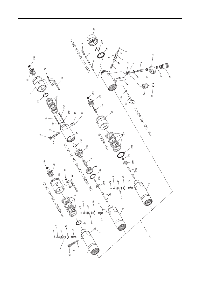
1R Screwdriver Motor Housing Assemblies Exploded Diagram
(Dwg. TPA-1857)
2 16574550_ed1
Page 3

1R Screwdriver Motor Housing Assemblies Parts List
Item Part Description Part Number Item Part Description Part Number
Motor Housing Assembly (for 1RL Models ending in S1 or S3) 3RL-510
for 1RA models 3RA-EU-A40 13F Throttle Valve Housing Cap Screw Lock
for 1RL models ending in Washer (4) (for 1RL Models
C1-, C3-, 9D- or D1- 3RL-EU-A40 ending in S1 or S3) 3RL-511
for 1RL models ending in 13G Throttle Ball
S1- or S3- 3RLS-EU-A40 (for 1RL Models ending in S1 or S3) 8U-722
for 1RP models 3RP-EU-A40 13H Throttle Ball Spring (for 1RL
1 Motor Housing † 14 Throttle Ball Spring
1A Valve Housing Alignment Pin (for for 1RL and 1RP Models (4) 3RL-311
2 Reverse Valve 3RL-329 (for 1RA and 1RT Models) 3RA-A123
• 2A Reverse Valve Seal WFS182-307 †• 18A Muffler O-Ring 85H-167
• 3 Reverse Valve Spring SPA102R-515 †• 18B Exhaust Deflector Seal
• 4 Valve Lock Pin SPA102R-667 (for 1RL and 1RP Models) 3RL-210
• 5 Retainer Setscrew SPA102R-669 19 Exhaust Defle ctor (for 1RP Models) 3RP-23
• 6 Lock Pin Retaine r 3RL-668 Exhaust Deflector Assembly
6A Throttle Valve Housing (for 1RL Models) 3RL-A23
†• 7 Throttle Valve Spring 21 Throttle Lever Pin (2) 3RL- 120
† 8 Throttle Valve (for 1RA and 1RT Models) 3RA-A93
†• 9 Valve Seat (for 1RA and 1RT Models) 7RAK-303 24 Back Cap Assembly
10 Valve Seat Support (for 1RA and 1RT Models) 3RA-A202
11 Throttle Valve Plunger † 25 Inlet Screen (for 1RA and 1RT R0A2-61
12 Throttle Valve Cap (for 1RL Models) 3RL-266 26 Inlet B ushing
• 13 Throttle Valve Ball (for 1RL Models) 4U-722 (for 1RA and 1RT Models) 3RA-465
13A Throttle Valve Housing Adapter 27 Inlet Bushing Spacer
• 13B Throttle Valve Housing Adapter Seal 28 Inlet Bushing Assembly
13C Exhaust Deflector Alignment † 28A Inlet Screen 3RL-61
13D Throttle Valve Housing Seal 28B Seat (for 1RL Models ending in S1 or
13E Throttle Valve Housing Cap Screw (4) 28C Nameplate 04725032
* Not illustrated.
• To keep downtime to a minimum, it is desirable to have on hand certain repair parts. We recommend that you stock one (pair or set) of each part
indicated by a bullet (•) for every four tools in service.
† Indicates Tune-up Kit part.
for 1RT models 3RT-EU-A40 Models ending in S1 or S3) 3RP-51
for 1RA and 1RT models 3RA-EU-B40 for 1RP Models 3RP-51
for 1RL models ending in for 1RT Models 3RT-51
C1-, C3-, 9D- or D1- 3RL-EU-B40 • 15 Throttle Ball (for 1RP and 1RT Models) 8U-722
for 1RL models ending in †• 16 Housing Seal (for 1RA and 1RT Models) 3RL-210
S1- or S3- 3RLS-EU-B40 †• 17 Muffler Element
for 1RP models 3RP-EU-B40 for 1RA and 1RT Models 3RA-310
1RL Models ending in S1 or S3) 3RL-15 18 Muffler Assembly
(for 1RL Models ending in S1 or S3) 3RL-503 20 Exhaust Deflector 3RL-23
for 1RA and 1RT Models 3RA-51 22 Throttle Lever 3 RL-273
for 1RL Models 3RL-51 • 23 Trigger Assembly
(for 1RA and 1RT Models) 7RAK-302 †• 23A Trigger Pin Seal 8SL-259
(for 1RA and 1RT Models) 7RAK-304 †• 24A Back Cap O-Ring AF120-290
(for 1RL Models) 3RL-302 Models)
(for 1RL Models ending in S1 or S3) 3RL-502 (for 1RA and 1RT Models) 3RA-65
(for 1RL Models ending in S1 or S3) PS3-67 (for 1RL and 1RP Models) 3RL-A465
Pin (for 1RL Models ending in S1 or S3) 3RL-15 * Warning Label WARNING-28-99
(for 1RL Models ending in S1 or S3) 3RL-210 S3 and all 1RA and 1RT Models) 3RP-303
16574550_ed1 3
Page 4

1R Motor and Gearing Exploded Diagram
FOR M, AND N RATIOS ONLY
M, N AND Q PARTS
L RATIO
(Dwg. TPA1858)
4 16574550_ed1
Page 5

1R Motor and Gearing Parts List
Item Part Description Part Number Item Part Description Part Number
29 Rotor for M ratio 3RLM-108
for 1RP and 1RT Models for N or Q ratios 3RLN-108
and 1RL Models ending in S1 or S3 3RP-53 44 Spindle Retaining Ring 3RL-6
for 1RA Models and 1RL 45 Rotor Pinion (for M, N or P ratios) 3RLM-17
Models ending in C1, C3, 9D or D1 3RL-53 46 Gear Head Spacer (for M, N and Q ratios) 3RL-80
30 Front End Plate 3RL-11 47 Gear Head
31 Rear End Pl ate for M ratio 3RLM-216
for 1RP, 1RT, 1RA and 1RL for N and P ratios 3RLN-216
Models 3RL-12 for Q ratio 3RLQ-216
†• 32 Rotor Bearing (2) DG10-22 for M, N and ratios (14 teeth) 3RLM-10
† 33 Rear Rotor Bearing Retainer 8SL-305 for Q ratio (19 teeth) 3RLL-10
† 34 Front Rotor Bearing Retainer 3RL-13 49 Motor Clamp Washer 3RL-207
† 35 Vane Packet (set of 5 Vanes) 3RL-42-5 50 Clamp Washer Retaining Ring 3RL-208
†• 38 Rear End Plate Gasket 3RL-739 * Han ger (for Models 1RA and 1RT) 3RA-365
* Not illustrated.
• To keep downtime to a minimum, it is desirable to have on hand certain repair parts. We recommend that you sto ck one (pair or set) of each part
indicated by a bullet (•) for every four tools i n service.
† Indicates Tune-up Kit part.
for 1RP and 1RTP Models 3RPP-12 48 Gear Head Planet Gear (3)
36 Cylinde r 3RL-3 * Suspension Bail
37 Cylinder D owel 3RL-98 (for Mo dels 1RL and 1RP) 7L-365
39 Gear Case Assembly * Hand Grip (for Models 1RL and 1RP) 3RP-747
for L ratio 3RLL-A37 * E xhaust Hose (for Models 1RL and 1RP) 3 RL-284
for M, N and Q ratios 3RLM-A37 * Tune-up Kit for 1RA and 1RT Models
40 Spindle Bearing R00A-510 (includes illustrated parts 7, 8, 9, 14, 16,
41 Spindle Bearing Retainer 3RL-28 17, 18A, 23A, 24A, 25, 32, 33, 34,
42 Spindle Planet Gear (3) 35 and 38) 3RA-TK2
for L ratio (19 teeth) 3RLL-10 * Tune-up Kit for 1RL and 1RP Models
for M ratio (14 teeth) 3RLM-10 (includes illustr ated parts 7, 14, 17, 18B,
for N and Q ratios (17 teeth) 3RLN-10 28A, 32, 33, 34, 35, and 38) 3RL-TK2
43 Spindle * Inlet Bushing (1/4" NPT) (for 1RL
for L ratio 3RLL-108 and 1RP Models only) 3RL-565
16574550_ed1 5
Page 6

1R Adjustable Cushion Clutch and Adjustable Shutoff Clutch Exploded Diagram
NON-ROTATING FINDER
NON-ROTATING FINDER
(Dwg. TPA1859)
6 16574550_ed1
Page 7

1R Adjustable Cushion Clutch and Adjustable Shutoff Clutch Parts List
Item Part Description
Adjustable Clutch Attachment (with light clutch spring) 3C1 3C3 3S1 3S3
100 Clutch Housing Assembly 3C1-A580A 3S3-A580 3C1-A580A 3S3-A580
101 Clutch Housing Bushing 3C1-781 3S3-781 3C1-781 3S3-781
102 Adjusting Hole Cover 3S3-415 3S3-415 3S3-415 3S3-415
103 Finder Retaining Spring --- 102A60-628 - -- 102A60-628
• 104 Clutch Return Spring --- --- 3S3-405 3S3-405
• 105 Clutch Spring
• 106A Clutch Driver Seal --- --- R0BRIC-283 R0BRIC-283
• 108 Clutch Ball (11) (1/8" diameter) AV1-255 AV1-255 --- -- -
• 109 Jaw Bearing Ball (10) (1/8" diameter) AV1-255 AV1-255 --- ---
• 111 Clutch Ball Seat 3C1-627 3C1-627 3S3-627 3S3-627
• 112 Thrust Bearing 161A32-105 161A 32-105 161A32-105 161A32-105
• 119 Collar Return Spring --- --- 3S3-407 3S3-407
• 121 Shutoff Plunger Ball (4) (3/32" diameter) --- --- R000B-263 R000B-263
• 123 Clutch Cam Ball (3) (1/4" diameter) --- --- 4U-722 4U-722
• 124 Bit Holder Bearing Ball (10) (1/8" diame ter) --- --- AV1-255 AV1-255
* Not illustrated.
• To keep downtime to a minimum, it is desirable to have on hand certain repair parts. We recommend that you stock one (pair or set) of each part
indicated by a bullet (•) for every four tools i n service.
† Bit Guide No. 5RA-69 is available for 1RA Models e nding in C3 or S3 and Models 1RLMC3 and 1RLNC3. It is av ailable for 1RP and 1RT Models
ending
in S3 and Models 1RLC3, 1RPMC3 and 1RPNC3.
¤ Bit Holder Assembly No. 3S3-586 is included with Clutch Driver Assembly No. 3S3-A581.
# Bit Holder No. 3S1-586 is included with Clutch Driver Assembl y No. 3S1-A581.
Clutch Driver Assembly (with light clutch spring) 3C1-A581 3C1-A581 3S1-A581 3S3-A581
Light (Black) 3S3-L583 3S3-L583 3S3-L583 3S3-L583
Medium (Yellow) 3S3-M583 3S3-M583 3S3-M583 3S3-M583
106 Clutch Driver 3C1-581 3C3-581 3S3-581 3S3-581
106B Clutch Driver Spacer --- --- 3S1-211 ---
107 Clutch Jaw 3C1-589 3C1-589 --- ---
110 Clutch Ball Spacer 3C1-401 3C1-401 --- ---
113 Clutch Spring Seat 3C1-623 3C1-623 3C1-623 3C1-623
114 Spring Seat Stop (3 for 3C1 or 3C3; 2 for 3S1 or 3S3
115 Adjusting Nut Lock 3S3-588 3S3-588 3S3-588 3S3-588
116 Adjusting Nut 3S3-582 3S3-582 3S3-582 3S3-582
117 Ball Retaining Ring --- --- 3S3-625 3S3-625
118 Shutoff Collar --- --- 3S3-402 3S3-402
120 Shutoff Plunger --- --- 3S3-408 3S3-408
122 Plunger Return Spring --- --- 3S3-420 3S3-420
125 Bit Holder Assembly --- 3C3-A586 --- 3S3-A586 ¤
126 Bit Retaining Spring --- 3S3-241 --- 3S3-241
127 Bit Retaining Ball --- R000B-263 --- R000B-263
128 Bit Holder 3C1-586 --- 3S1-586 # ---
129 Retaining Sleeve Spring 5C1-931-4 --- 5C1-931-4 ---
129A Sleeve Spring Retainer (Blue) 5C1-853 --- 5C1-853 ---
130 Bit Retaining Sleeve 5 C1-930-4 --- 5C1-930-4 ---
131 Bit Retaining Ball (9/64" diameter) RX1-629 --- RX1-629 ---
132 Bit Retaining Sleeve Stop 5C1-729 --- 5C1-729 - --
133 Disengaging Spring 3S3-420 3S3-420 --- ---
134 Finder Spring --- 102A60-242 -- - 102A60-242
135 Push Rod --- 3RP-435 3RP-435
* Clutch Adjusting Key 5C1-416 5C1- 416 5C1-416 5C1-416
* Bit Guide (Available for Models endin g in C3 or S3) --- 5RA- 69 † -- - 5R A-69 †
Heavy (Green) 3S3-H583 3S3-H583 3S3-H583 3S3-H583
Clutch) 3S3-701 3S3-701 3S3-701 3S3-701
For 1RA or 1RL Models
Ending in C1 or C3
For 1RL, 1RP or 1RT
Models Ending in S1 or
S3
16574550_ed1 7
Page 8

1R Adjustable Cushion Clutch and Direct Drive Attachments Exploded Diagram
NON-ROTATING FINDER
(Dwg. TPA1860)
8 16574550_ed1
Page 9

1R Adjustable Cushion Clutch and Direct Drive Attachments Parts List
Item Part Description
Adjustable Clutch Attachment (with light c lutch spring) P3C1 P3C3 ---
100 Clutch Housing Assembly 3C1-A580A 3S3-A580 A ---
101 Clutch Housing Bushing 3C1-781 3S3-781 ---
102 Adjusting Hole Cover 3S3-415 3S3-415 ---
103 Finder Retaining Spring --- 102A60-628 ---
• 104 Clutch Return Spring 3S3-405 3S3-405 ---
• 105 Clutch Spring
• 108 Clutch Ball (11) (1/8" diameter) AV1-255 AV1-255 ---
• 109 Jaw Bearing B all (10) (1/8" diameter) AV1-255 AV1-255 ---
• 111 Clutch Ball Seat 3 C1-627 3C1-627 ---
• 112 Thrust Bearing 161A32-105 161A32-105 ---
* Not illustrated.
• To keep downtime to a minimum, it is desirable to have on hand certain repair parts. We recommend that you stock one (pair o r set) of each part
indicated by a bullet (•) for every four tools i n service.
Clutch Driver Assembly (with light clutch spring) 3C1-A581 3C1-A 581 ---
Light (Black) 3S3-L583 3S3-L583 ---
Medium (Yellow) 3S3-M583 3S3-M583 ---
106 Clutch Driver 3C1-581 3C1-581 ---
107 Clutch Jaw 3C1-589 3C1-589 ---
110 Clutch Ball Spacer 3C1-401 3C1-401 ---
113 Clutch Spring Seat 3C1-623 3C1-623 ---
114 Spring Seat Stop (3) 3S3-701 3S3-701 ---
115 Adjusting Nut Lock 3S3-588 3S3-588 ---
116 Adjusting Nut 3S3-582 3S3-582 ---
125 Bit Holder Assembly --- 3C3-A586 ---
126 Bit Retaining Spring --- 3S3-241 ---
127 Bit Retaining Ball --- R000B-263 ---
128 Bit Holder 3C1-586 --- ---
129 Retaining Sleeve Spring 5C1-931-4 --- ---
129A Sleeve Spring Retainer (Blue) 5 C1-853 --- ---
130 Bit Retaining Sleeve 5C1-930-4 --- ---
131 Bit Retaining Ball (9/64" diameter) RX1-629 --- ---
132 Bit Retaining Sleeve Stop 5C1-729 --- ---
134 Finder Spring --- 102A60-242 ---
135 Push Rod 3RP-435 3RP-435 ---
* Clutch Adjusting Key 5C1-416 5C1-416 ---
150 Screwdriver Housing Assembly --- --- 3D1-A580
151 Housing Bushing --- --- 3D1-781
152 Bit Retaining Ball --- --- RX1-629
153 Bit Holder Retaining Ring (2) --- --- 5C1-729
154 Bit Holder --- --- 3D1-786
155 Bit Retaining Sleeve --- --- 5C1-930-4
156 Retaining Sleeve Spring --- --- 5C1-931-4
157 Sleeve Spring Retainer (Blue) --- --- 5C1-853
Heavy (Green) 3S3-H583 3S3- H583 ---
Direct Drive Attachment --- --- 3DI
For 1RP Models
Ending in C1 or C3
For Models
Ending in D1
16574550_ed1 9
Page 10

1R Clutches For 5/16” Hexagon Shank European Style Bits Exploded Diagram
(Dwg. TPA1861)
10 16574550_ed1
Page 11

1R Clutches For 5/16” Hexagon Shank European Style Bits Parts List
For 1RA or
Item Part Description
Adjustable Clutch Attachment (with Light Clutch Spring) 3C9D 3S9D P3C9D
100 Clutch Housing Assembly 3C9D-A580 3C9D-A580 3C9D-A580
102 Adjusting Hole Cover 3S3-415 3S3-415 3S3-415
103 Clutch Housing Cap 3C9D-19 3C9D-19 3C9D-19
• 104 Clutch Return Spring --- 3S3-405 3S3-405
• 105 Clutch Spring
• 108 Clutch Ball (11) (1/8" diameter) AV1-255 --- AV1-255
• 109 Jaw Bearing Ball (10) (1/8" diameter) AV1-255 --- AV1-255
• 111 Clutch Ball Seat 3C1-627 3S3-627 3C1-627
• 112 Thrust Bearing 161A32-105 161A32-105 161A32-105
• 119 Collar Return Spring --- 3S3-407 ---
• 121 Shutoff Plunger Ball (4) (3/32" diameter) --- R000B-263 ---
• 123 Clutch Cam Ball (3) (1/4" diameter) --- 4U-722 ---
• 124 Bit Holder Bearing Ball (10) (1/8" diame ter) --- AV1-255 ---
• 133 Disengaging Spring 3S3-420 --- ---
* Not illustrated.
• To keep downtime to a minimum, it is desirable to have on hand certain repair parts. We recommend that you stock o ne (pair or set) of each part
indicated by a bullet (•) for every four tools i n service.
¤ Bit Holder Assembly No. 3S9D-A586 is included w ith Clutch Driver Assembly No. 3S9D-A581.
Clutch Driver Assembly (with light clutch spring) 3C1-A581 3S9D-A581 3C1-A581
Light (Black) 3S3-L583 3S3-L583 3S3-L583
Medium (Yellow) 3S3-M583 3S3-M583 3S3-M583
106 Clutch Driver 3C1-581 3S3-581 3C1-581
106A Clutch Driver Seal --- R0BR1C-283 ---
106B Clutch Driver Spacer --- 3S9D-211 ---
107 Clutch Jaw 3C1-589 --- 3C1-589
110 Clutch Ball Spacer 3C1-401 --- 3C1-401
113 Clutch Spring Seat 3C1-623 3C1-623 3C1-623
114 Spring Seat Stop (3 for 3C9D and P3C9D; 2 for 3S9D) 3S3-701 3S3-701 3S3-701
115 Adjusting Nut Lock 3S3-588 3S3-588 3S3-588
116 Adjusting Nut 3S3-582 3S3-582 3S3-582
117 Ball Retaining Spring --- 3S3-625 ---
118 Shutoff Collar --- 3S3-402 ---
120 Shutoff Plunger --- 3S3-408 ---
122 Plunger Return Spring --- 3S3-420 ---
125 Bit Holder Assembly 3C9D-A586 3S9D-A5 86 ¤ 3C9D-A586
126 Bit Retaining Spring 3C9D-241 3C9D-241 3C9D-241
127 Bit Retaining Ball AV 1-255 AV1-255 AV1-255
135 Push Rod --- 3RP-435 3RP-435
* Clutch Adjusting Key 5C1-416 5C1- 416 5C1-416
Heavy (Green) 3S3-H583 3S3-H583 3S3-H583
1RL Models
Ending in
C9D
For 1RP or
1RT Models
Ending in
S9D
For 1RP or
Models
Ending in
C9D
16574550_ed1 11
Page 12

Clutch Spring Selection Chart
Model
1RALC1 3.5 to 13 in-lb (.39 to 1.5 Nm) --- ---
1RALC3 3.5 to 13 in-lb (.39 to 1.5 Nm) --- ---
1RAMC1 2.5 to 16 in-lb (.28 to 1.8 Nm) 3.0 to 20 in-lb (.3 4 to 2.3 Nm) ---
1RAMC3 2.5 to 16 in-lb (.28 to 1.8 Nm) 3.0 to 20 in-lb (.3 4 to 2.3 Nm) ---
1RANC1 1.5 to 16 in-lb (.17 to 1.8 Nm) 2.5 to 23 in-lb (.28 to 2.6 Nm) 5.0 to 30 in-lb (.56 to 3.4 Nm)
1RANC3 1.5 to 16 in-lb (.17 to 1.8 Nm) 2.5 to 23 in-lb (.28 to 2.6 Nm) 5.0 to 30 in-lb (.56 to 3.4 Nm)
1RAQC1 --- --- 5. 0 to 45 in-lb (.56 to 5.1 Nm)
1RLLC1 3.5 to 13 in-lb (.39 to 1.5 Nm) --- ---
1RLLC3 3.5 to 13 in-lb (.39 to 1.5 Nm) --- ---
1RLMC1 2.5 to 16 in-lb (.28 to 1.8 Nm) 3.0 to 20 in-lb (.34 to 2.3 Nm) ---
1RLMC3 2.5 to 16 in-lb (.28 to 1.8 Nm) 3.0 to 20 in-lb (.34 to 2.3 Nm) ---
1RLNC1 1.5 to 16 in-lb (.17 to 1.8 Nm) 2.5 to 23 in-lb (.28 to 2.6 Nm) 5.0 to 30 in-lb (.56 to 3.4 Nm)
1RLNC3 1.5 to 16 in-lb (.17 to 1.8 Nm) 2.5 to 23 in-lb (.28 to 2.6 Nm) 5.0 to 30 in-lb (.56 to 3.4 Nm)
1RLNS1 1.5 to 16 in-lb (.17 to 1.8 Nm) 2.5 to 23 in- lb (.28 to 2.6 Nm) 5.0 to 30 in-lb (.56 to 3.4 Nm)
1RLQS1 --- --- 5.0 to 45 in-lb (.56 to 5.1 Nm)
1RLNS3 1.5 to 16 in-lb (.17 to 1.8 Nm) 2.5 to 23 in- lb (.28 to 2.6 Nm) 5.0 to 30 in-lb (.56 to 3.4 Nm)
1RLQS3 --- --- 5.0 to 45 in-lb (.56 to 5.1 Nm)
1RPLC1 3.5 to 13 in-lb (.39 to 1.5 Nm) --- ---
1RPLC3 3.5 to 13 in-lb (.39 to 1.5 Nm) --- ---
1RPMC1 2.5 to 16 in-lb (.28 to 1.8 Nm) 3.0 to 20 in-lb (.3 4 to 2.3 Nm) ---
1RPMC3 2.5 to 16 in-lb (.28 to 1.8 Nm) 3.0 to 20 in-lb (.3 4 to 2.3 Nm) ---
1RPNC1 1.5 to 16 in-lb (.17 to 1.8 Nm) 2.5 to 23 in-lb (.28 to 2.6 Nm) 5.0 to 30 in-lb (.56 to 3.4 Nm)
1RPNC3 1.5 to 16 in-lb (.17 to 1.8 Nm) 2.5 to 23 in-lb (.28 to 2.6 Nm) 5.0 to 30 in-lb (.56 to 3.4 Nm)
1RPLS1 3.5 to 13 in-lb (.39 to 1.5 Nm) --- ---
1RPMS1 2.5 to 16 in-lb (.28 to 1.8 Nm) 3.0 t o 20 in-lb (.34 to 2.3 Nm) ---
1RPNS1 1.5 to 16 in-lb (.17 to 1.8 Nm ) 2.5 to 23 in-lb (.28 to 2.6 Nm) 5.0 to 30 in-lb (.56 to 3.4 Nm)
1RPPS1 1.5 to 16 in-lb (.17 to 1.8 Nm) 2.5 to 23 in-lb (.28 to 2.6 Nm) ---
1RPQS1 --- --- 5.0 to 45 in-lb (.56 to 5.1 Nm)
1RTLS1 3.5 to 13 in-lb (.39 to 1.5 Nm) --- ---
1RTMS1 2.5 to 16 in-lb (.28 to 1.8 Nm) 3.0 to 20 in-lb (.34 to 2.3 Nm) ---
1RTNS1 1.5 to 16 in-lb ( .17 to 1.8 Nm) 2.5 to 23 in-lb (.28 to 2.6 Nm) 5.0 to 30 in-lb (.56 to 3.4 Nm)
1RTPS1 1.5 to 16 in-lb (.17 to 1.8 Nm) 2.5 to 23 in-lb (.2 8 to 2.6 Nm) ---
1RTQS1 --- --- 5.0 to 45 in-lb (.56 to 5.1 Nm)
1RPLS3 3.5 to 13 in-lb (.39 to 1.5 Nm) --- ---
1RPMS3 2.5 to 16 in-lb (.28 to 1.8 Nm) 3.0 t o 20 in-lb (.34 to 2.3 Nm) ---
1RPNS3 1.5 to 16 in-lb (.17 to 1.8 Nm ) 2.5 to 23 in-lb (.28 to 2.6 Nm) 5.0 to 30 in-lb (.56 to 3.4 Nm)
1RPPS3 1.5 to 16 in-lb (.17 to 1.8 Nm) 2.5 to 23 in-lb (.28 to 2.6 Nm) ---
1RPQS3 --- --- 5.0 to 45 in-lb (.56 to 5.1 Nm)
1RTLS3 3.5 to 13 in-lb (.39 to 1.5 Nm) --- ---
1RTMS3 2.5 to 16 in-lb (.28 to 1.8 Nm) 3.0 to 20 in-lb (.34 to 2.3 Nm) ---
1RTNS3 1.5 to 16 in-lb ( .17 to 1.8 Nm) 2.5 to 23 in-lb (.28 to 2.6 Nm) 5.0 to 30 in-lb (.56 to 3.4 Nm)
1RTPS3 1.5 to 16 in-lb (.17 to 1.8 Nm) 2.5 to 23 in-lb (.2 8 to 2.6 Nm) ---
1RTQS3 --- --- 5.0 to 45 in-lb (.56 to 5.1 Nm)
1RAMC9D 2.5 to 16 in-lb (.28 to 1.8 Nm) 3.0 to 20 in-lb (.34 to 2.3 Nm) ---
1RANC9D 1.5 to 16 in-lb (.17 to 1.8 Nm) 2.5 to 23 in-lb (.28 to 2.6 Nm) 5.0 to 30 in-lb (.56 to 3.4 Nm)
1RLMC9D 2.5 to 16 in-lb (.28 to 1.8 Nm) 3.0 to 20 in-lb (.34 to 2.3 Nm) ---
1RLNC9D 1.5 to 16 in-lb (.17 to 1.8 Nm) 2.5 to 23 in-lb (.28 to 2.6 Nm ) 5.0 to 30 in-lb (.56 to 3.4 Nm)
1RPMC9D 2.5 to 16 in-lb (.28 to 1.8 Nm) 3.0 to 20 in-lb (.34 to 2.3 Nm) ---
1RPNC9D 1.5 to 16 in-lb (.17 to 1.8 Nm) 2.5 to 23 in-lb (.28 to 2.6 Nm) 5.0 to 30 in-lb (.56 to 3.4 Nm)
1RPMS9D 2.5 to 16 in-lb (.28 to 1.8 Nm) 3.0 t o 20 in-lb (.34 to 2.3 Nm) ---
1RPNS9D 1.5 to 16 in-lb (.17 to 1.8 Nm ) 2.5 to 23 in-lb (.28 to 2.6 Nm) 5.0 to 30 in-lb (.56 to 3.4 Nm)
1RPPS9D 1.5 to 16 in-lb (.17 to 1.8 Nm) 2.5 to 23 in-lb (.28 to 2.6 Nm) ---
1RTMS9D 2.5 to 16 in-lb (.28 to 1.8 Nm) 3.0 to 20 in-lb (.34 to 2.3 Nm) ---
1RTNS9D 1.5 to 16 in-lb ( .17 to 1.8 Nm) 2.5 to 23 in-lb (.28 to 2.6 Nm) 5.0 to 30 in-lb (.56 to 3.4 Nm)
1RTPS9D 1.5 to 16 in-lb (.17 to 1.8 Nm) 2.5 to 23 in-lb (.28 to 2.6 Nm) ---
Light Clutch Spring
(Black)
Torque Range (Soft Draw)
Medium Clutch Spring
(Yellow)
Heavy Clutch Spring
(Green)
12 16574550_ed1
Page 13

Parts and Maintenance
When the life of the tool has expired, it is recomm ended that the tool be disassembled, degreased and parts be separated by material so that they can be
recycled.
Tool repair and maintenance should only be carried out by an authorized Service Ce nter.
Refer all communications to the nearest Ingersoll-Rand Office or Distributor.
Related Documentation
For additional information refer to:
Product Safety Information Manual 04585006.
Product Information Manual 80167265.
Product Maintenance Information Manual 16575243.
Manuals can be downloaded from www.irtools.com.
16574550_ed1 13
Page 14

Notes
14 16574550_ed1
Page 15

Notes
16574550_ed1 15
Page 16

www.irtools.com
© 2006 Ingersoll-Rand Company
 Loading...