

Page 1
Before installation or starting the compressor for the
first time, this manual should be studied carefully to
obtain a clear knowledge of the unit and of the duties
to be performed while operating and maintaining the
unit.
RET AIN THIS MANUAL WITH UNIT.
This Technical manual contains IMPORTANT SAFETY
DATA and should be kept with the air compressor at
all times.
125-200 HP/90-160 KW
SINGLE STAGE
AND
100-200 HP/75-160 KW
TWO STAGE UNITS
OPERATORS/
INSTRUCTION MANUAL
OPTIONS
FORM: APDD 738B
November 2002
More Than Air. Answers.
Online answers: http://www.air.irco.com
Phone: 1-800-526-3615
CCN: 80440415 REV: B
Page 2

AIR COMPRESSOR GROUP
BONDED WARRANTY & REGISTERED START UP
Warranty
The Company warrants that the equipment manufactured b y it and deliv ered hereunder will be free of def ects in material
and workmanship for a period of twelve months (see extended airend warranty) from the date of placing the Equipment
in operation or eighteen months (see extended airend warranty) from the date of shipment from Davidson, NC, whichever
shall first occur.The Purchaser shall be obligated to promptly report any failure to conform to this warranty, in writing to
the Company in said period, whereupon the Company shall, at its option, correct such nonconformity, by suitable repair
to such equipment or, furnish a replacement part F.O.B.point of shipment, provided the Purchaser has stored, installed
maintained and operated such Equipment in accordance with good industry practices and has complied with specific
recommendations of the Company. Accessories or equipment furnished by the Company, but manufactured by others,
shall carry whatever warranty the manufacturers have conveyed to the Company and which can be passed on to the
Purchaser.The Company shall not be liable for any repairs, replacements, or adjustments to the Equipment or any costs
of labor performed by the Purchaser or others without Company’s prior written approval.
The effects of corrosion, erosion and normal wear and tear are specifically excluded.Perf ormance warranties are limited
to those specifically stated within the Company’s proposal.Unless responsibility for meeting such perf ormance warranties
are limited to specified tests, the Company’s obligation shall be to correct in the manner and for the period of time
provided above.
THE COMPANY MAKES NO OTHER WARRANTY OR REPRESENTATION OF ANY KIND WHATSOEVER,
EXPRESSED OR IMPLIED, EXCEPT THAT OF TITLE, AND ALL IMPLIED WARRANTIES OF MERCHANTABILITY
AND FITNESS FOR A PARTICULAR PURPOSE, ARE HEREBY DISCLAIMED.
Correction by the Company of nonconformities whether patent or latent, in the manner and for the period of time
provided above, shall constitute fulfillment of all liabilities of the Company for such nonconformities whether based on
contract, warranty negligence, indemnity, strict liability or otherwise with respect to or arising out of such Equipment.
The purchaser shall not operate Equipment which is considered to be defective, without first notifying the Company in
writing of its intention to do so. Any such Equipment will be at Purchaser’s sole risk and liability.
Note that this is Ingersoll-Rand’s standard warranty. Any warranty in force at the time of purchase of the compressor or
negotiated as part of the purchase order may take precendence over this warranty.
©INGERSOLL-RAND COMPANY
Page 3
1
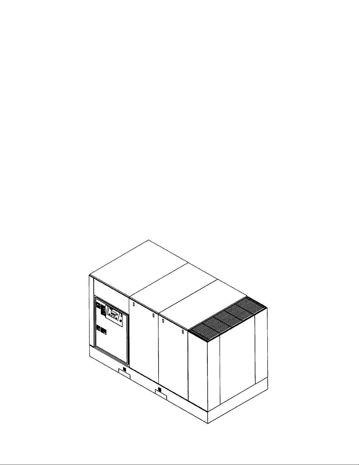
ROTARY SCREW AIR COMPRESSOR
This unit was purchased from:
_______________________________________________
_______________________________________________
_______________________________________________
Ingersoll-Rand Company reserves the right to make
changes or add improvements without notice and without
incurring any obligation to make such changes or add such
improvements to products sold previously.
Number of units on order: __________________________
Customer Order Number: __________________________
Ingersoll-Rand Company Order Number: ______________
For ready reference, record the serial number and
model number of your unit here:
Serial Number: ___________________________________
Model Number: ___________________________________
Page 4

2
TABLE OF CONTENTS
0.0 SAFETY AND WARNINGS
0.1 safety instructions
0.2 safety precautions
0.3 decals
1.0 RECEIPT OF EQUIPMENT
1.1 inspection
1.2 unpacking and handling
1.3 tools
2.0 INSTALLATION
2.1 ventilation
2.2 foundation requirements
2.3 piping
2.4 electrical installation
2.5 outdoor sheltered
3.0 INTELLISYS
®
3.1 intellisys controls
3.2 display screen
3.3 current status
3.4 main menu
3.5 operator setpoints
3.6 options
3.7 sensor calibration
3.8 alarm history
3.9 warnings
3.10 alarms
4.0 SCHEDULED PREVENTATIVE MAINTENANCE
4.1 maintenance schedule
4.2 maintenance records
4.3 maintenance procedures
4.4 inlet air filter
4.5 coolant filter
4.6 coolant
4.7 separator tank scavenge screen/orifice
4.8 coolant separator element
4.9 cooler cores (cleaning)
4.10 motor lubrication
4.11 long term storage
4.12 coolant/lubricant changeout
4.13 intellisys removal
4.14 coolant hoses
4.15 fluid and vibration monitoring
4.16 coolant sampling procedure
5.0 SYSTEMS
5.1 general system information
5.2 air cooled compressors
5.3 coolant system
5.4 compressed air system
5.5 coolant/air separation system
5.6 electrical system
5.7 stepper motor inlet control
5.8 capacity control system
5.9 automatic start/stop control
5.10 remote start/sto
6.0 TROUBLESHOOTING
7.0 OPTIONS
7.1 power outage restart option
7.2 sequencer
7.3 low ambient
7.4 separator delta-p solenoid
7.5 separator delta-p sensor
7.6 high dust filter
7.7 lead/lag cycle length
7.8 schedule start/stop
7.9 remote load/unload
7.10 modbus
7.11 integral sequencing
8.0 REFERENCE DRAWINGS
8.1 electrical schematic, star delta
8.2 foundation plan, 125/150 HP, A/C - Single Stage
8.3 foundation plan, 200 HP, A/C - Single Stage
8.4 foundation plan, 125/150 HP,W/C - Single Stage
8.5 foundation plan, 200 HP,W/C - Single Stage
8.6 foundation plan, 125/150 HP, A/C - Two Stage
8.7 foundation plan, 200 HP, A/C - Two Stage
8.8 foundation plan, 125/150 HP,W/C - Two Stage
8.9 foundation plan, 200 HP,W/C - Two Stage
8.10 flow schematic, A/C - Single Stage
8.11 flow schematic,W/C-90°F (32°C) - Single Stage
8.12 flow schematic,W/C-115°F (46°C) - Single Stage
8.13 flow schematic, A/C - Two Stage
8.14 flow schematic,W/C-90°F (32°C) - Two Stage
8.15 flow schematic,W/C-115°F (46°C) - Two Stage
8.16 typical system flow diagrams
9.0 WATER QUALITY RECOMMENDATIONS
10.0 MAINTENANCE RECORD
Weight..............................See foundation plan, Section 8.0
Cooling Air Flow.............See foundation plan, Section 8.0
Ambient Temperature Limits..........................35°F to 115°F
...........................................................................((2°C to 46°C)
Coolant.............................Factory Filled SSR Ultra Coolant
Coolant Change ............................8000 hours or two years
............................................................whichever comes first
Coolant Capacity
125/200 HP (90-160 KW) -
Single Stage ...................................23.0 gallons (87.4 liters)
100 HP (75 KW) -
Two Stage.......................................22.0 gallons (83.3 liters)
125-200 HP (90-160 KW) -
Two Stage.....................................30.0 gallons (113.6 liters)
Discharge Temperature Limit.........................228°F (109°C)
Power Inlet Wiring .........................Recommended conduit:
............................metallic flexible Greenfield, or equivalent
Tools..............................................U.S. standard and metric
...................................are required to perform maintenance
Page 5
3
0.0 SAFETY AND WARNINGS
0.1 SAFETY INSTRUCTIONS Before you install this air compressor you should take the time to carefully read all the instructions contained in this manual.
Electricity and compressed air have the potential to cause
severe personal injury or property damage.
Before installing, wiring, starting, operating or making any
adjustments, identify the components of the air
compressor using this manual as a guide.
The operator should use common sense and good
working practices while operating and maintaining this
unit. Follow all codes, pipe adequately, understand the
starting and stopping sequence. Check the safety devices
by following the procedure contained in this manual.
Maintenance should be done by qualified personnel,
adequately equipped with proper tools. Follow the
maintenance schedules as outlined in the operators
manual to ensure problem free operation after start up.
Safety instructions in the operators manual are bold-faced
for emphasis. The signal words DANGER, WARNING and
CAUTION are used to indicate hazard seriousness levels
as follows:
Danger is used to indicate the presence of
a hazard which will cause severe personal
injury, death, or substantial property
damage if the warning is ignored.
Warning is used to indicate the presence of
a hazard which can cause severe personal
injury, death, or substantial property
damage if the warning is ignored.
Caution is used to indicate the presence of
a hazard which will or can cause minor
personal injury or property damage if the
warning is ignored.
Notice is used to notify people of
installation, operation, or maintenance
information which is important but not
hazard-related.
D! DANGER
! WARNING
! CAUTION
NOTICE
WARNING
COMPRESSED AIR AND ELECTRICITY
ARE DANGEROUS.
BEFORE DOING ANY WORK ON THIS
UNIT,BE SURE THE ELECTRICAL SUPPLY
HAS BEEN CUT OFF–LOCKED & TAGGED
AND THE ENTIRE COMPRESSOR SYSTEM
HAS BEEN VENTED OF ALL PRESSURE.
1. Do not remove the covers, loosen or
remove any fittings, connections or
devices when this unit is in operation. Hot
liquid and air under pressure that are
contained within this unit can cause
severe injury or death.
2. The compressor has high and
dangerous voltage in the motor starter and
control box. All installations must be in
accordance with recognized electrical
codes. Before working on the electrical
system, be sure to remove voltage from
the system by use of a manualdisconnect-switch. A circuit breaker or
fuse safety switch must be provided in the
electrical supply line leading to the
compressor.
Those responsible for installation of this
equipment must provide suitable grounds,
maintenance clearance and lightning
arrestors for all electrical components as
stipulated in O.S.H.A. 1910.308 through
1910.329.
3. Do not operate the compressor at higher
discharge pressure than those specified
on the Compressor Nameplate or motor
overload will occur. This condition will
result in compressor motor shutdown.
4. Use only safety solvent for cleaning the
compressor and auxiliary equipment.
5. Install a manual shut off valve (isolation
type) in the discharge line. When a safety
valve is installed between the isolation
valve and the compressor, it must have
sufficient capacity to relieve the full
capacity of the compressor(s).
6. Whenever pressure is released through
the pressure relief valve, it is due to
excessive pressure in the system. The
cause for the excessive pressure should
be investigated immediately.
7. Before doing any mechanical work on
the compressor:
a.) Shut the unit down.
b.) Electrically isolate the compressor by
use of the manual disconnect switch in the
power line to the unit. Lock and tag the
switch so that it cannot be operated.
c.) Vent pressure from the compressor and
isolate the unit from any other source of
air.
8. There can be adverse effects if
compressor lubricants are allowed to enter
plant air systems.
Air line separators, properly selected and
installed, will minimize any liquid carryover.
The use of plastic bowls on line filters
without metal guards can be hazardous.
From a safety standpoint, metal bowls
should be used on any pressurized
system. Review of your plant air line
system is recommended.
9. When a receiver is installed, it is
recommended that occupational safety
and health standards as covered in the
Federal Register, Volume 36, number 105,
part 11, paragraph 1910.169 be adhered to
in the installation and maintenance of this
receiver.
10. Before starting the compressor, its
maintenance instructions should be
thoroughly read and understood.
11. After maintenance functions are
completed, covers and guards must be
replaced.
0.2 SAFETY PRECAUTIONS
SAFETY PRECAUTIONS
BEFORE PROCEEDING, READ CAREFULLY BEFORE INSTALLING THE
COMPRESSOR OR PERFORMING ANY MAINTENANCE
Page 6
4
WARNING
Failure to adhere to these recommendations can result in mechanical failure, property damage and serious injur y or death.
All air and water inlet, and air and water discharge pipework to and from the inlet and discharge port connections must take
into account vibration, pulsations, temperature, maximum pressure applied, corrosion and chemical resistance. In addition, it
should be noted that lubricated compressors will discharge some oil into the air stream; therefore, compatibility between
discharge piping, system accessories and software must be assured.
For the foregoing reasons, the use of plastic piping, soldered copper fittings and rubber hose as discharge piping is not
recommended. In addition, flexible joints and/or flex lines can only be considered for such purposes if their specifications fit
the operating parameters of the system.
It is the responsibility of the installer and owner to provide the appropriate service pipework to and from the machine.
WARNING
CHECK HIGH AIR TEMPERATURE
There is a high discharge air temperature shutdown function built into the Intellisys on each compressor. It is factory pre-set
at 228°F (109°C).This function should be checked at regular intervals for proper operation, once a month is recommended.
The procedure is:
1. Block off the cooling air discharge.
2. The compressor discharge temperature will rise at a rapid rate.Shutdown should occur when the discharge
temperature reaches the pre-set maximum discharge air temperature setting of the Intellisys.The display should
indicate “HIGH AIREND DISCH TEMP” and flash “ALARM”.
The actual temperature at which shutdown occurs should be recorded for comparison to the Intellisys set point and with
similar future test results.
SAFETY SHUTDO WN
“Ingersoll-Rand air compressors are not designed, intended, or approved for breathing air.Ingersoll-Rand does not approve
specialized equipment for breathing air application and assumes no responsibility or liability for compressors used for
breathing air services.”
Page 7
39540174 Rev. 05
5
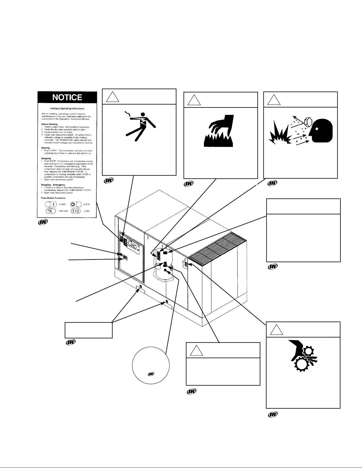
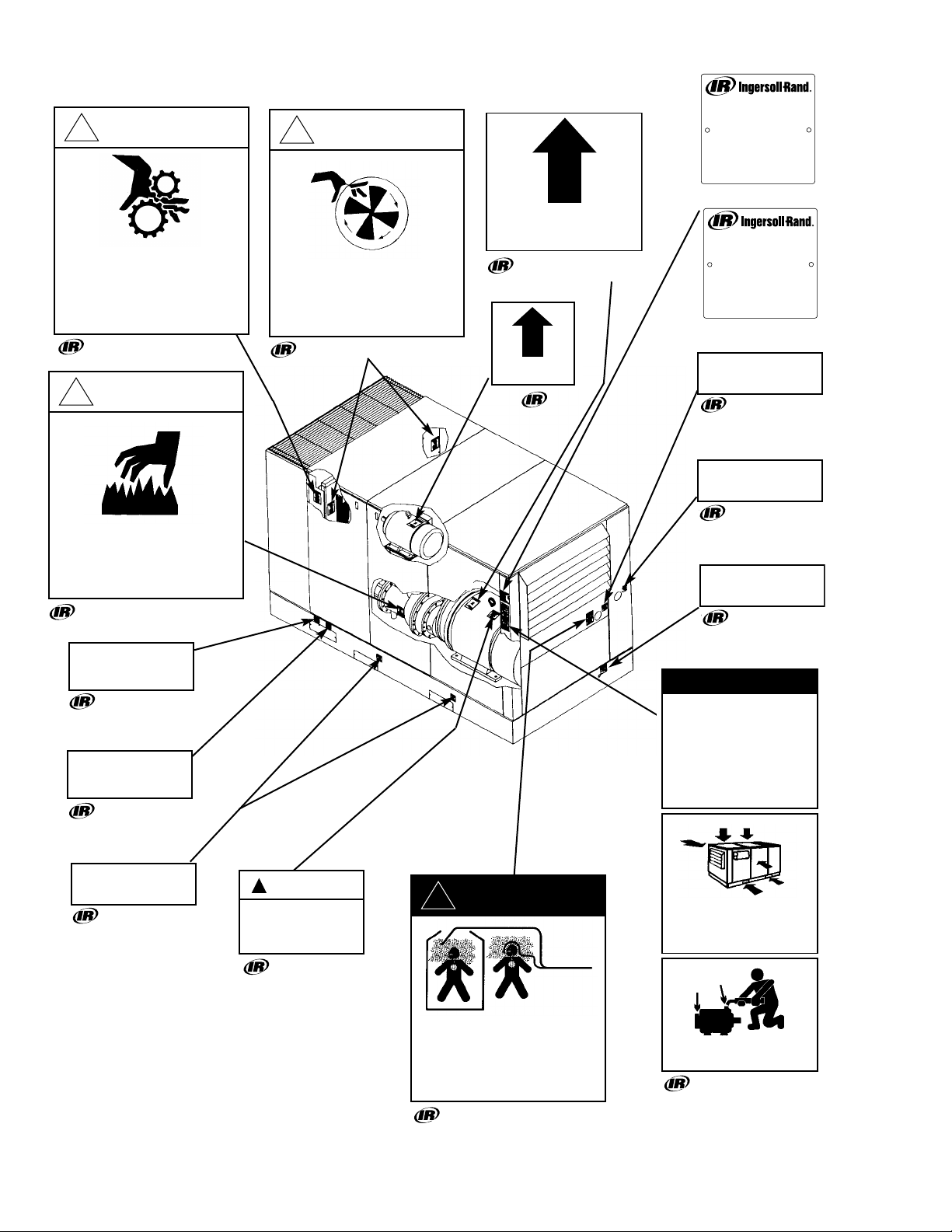
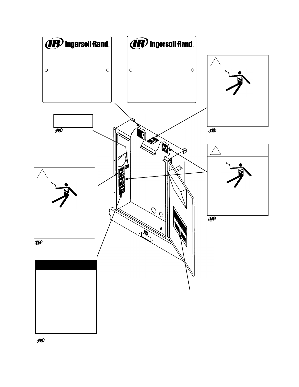
0.3 DECALS
This section contains representative examples of decals
which will be appearing throughout this manual and are
applied to the compressor unit. If for some reason a
decal is defaced, painted over, or parts are replaced, we
recommend that you obtain a replacement kit as listed in
the spare parts section of the Parts List Manual Form
APDD 735 for single stage and Form APDD 736 for two
stage units.
*PORO OPTION
39584529
*REMOTE START-
STOP OPTION
39547708
*FOOD GRADE
COOLANT OPTION
39568803
* FOOD GRADE COOLANT
OPTION 39568464
* FOOD GRADE COOLANT
OPTION ONLY
*ITEMS MARKED WITH * ARE OPTIONS THAT
ARE AVAILABLE
2 REQUIRED - BASE
VIEWED
FROM
FRONT
39541362 Rev. 04
39540240 Rev. 04
39544143 Rev. 03
39540224 Rev. 04
39543921 Rev. 03
39540265 Rev. 05
39540273 Rev. 04
39878657 Rev. 03
!
WARNING
Hazardous voltage. Can cause
severe injury or death.
Disconnect power before servicing.
Lockout/Tagout machine.
!
WARNING
Hot surface.
Can cause severe injury.
Do not touch. Allow to cool before
servicing.
!
WARNING
High pressure air.
Can cause severe injury or death.
Relieve pressure before removing filter
plugs / caps, fittings or covers.
CAUTION
Improper maintenance of
coolant filter can cause
compressor damage.
Change coolant filter after first
150 hours of operation and
every 2000 hours thereafter or
when coolant is changed.
Lift Here
Filler Cap.
Use only
recommended coolant.
Read instruction book
before servicing.
39543921
!
CAUTION
Use of incorrect coolant can cause
system contamination.
Use only SSR ULTRA COOLANT.
!
WARNING
Moving parts.
Can cause severe injury.
Do not operate with covers removed.
Service only with machine blocked to
prevent turn over.
Page 8
0.3 DECALS (continued)
6
39540224 Rev. 04
39540232 Rev.03
39544150 Rev. 03
39557095 Rev.05 (100-200 HP)
54425996 Rev.C (75-160KW)
39541354 Rev. 03
39540166 Rev. 06
39540257 Rev. 04
39541081 Rev. 04
39540273 Rev. 04
39541339 Rev. 03
39541321 Rev. 04
39541362 Rev. 04
39540182 Rev. 04
* WATERCOOLED UNITS ONLY
VIEWED
FROM
REAR
*
*
39540190 Rev. 04
39857552 Rev. 04
!
WARNING
!
WARNING
Compressor Package Data
COMPRESSOR MODEL...............................
CAPACITY......................................................
RATED OPERATING PRESSURE.................
MAX.DISCHARGE PRESSURE...................
MAX.MODULATE PRESSURE.....................
NOMINAL DRIVE MOTOR............................
NOMINAL FAN MOTOR................................
TOTAL PACKAGE AMPS...............................
VOLTS............................................................
PHASE / HERTZ............................................
CONTROL VOLTAGE.....................................
SERIAL NUMBER..........................................
CONTACTOR AMP.RATING.....................................
ASSEMBLY AMP.RATING........................................
LOCKED ROTOR AMP. RATING OF ASSY.............
AIR SOLUTIONS GROUP
DAVIDSON,NORTH CAROLINA 28036
WWW.AIR.INGERSOLL-RAND.COM
m3/MIN
BARG
BARG
BARG
KW
KW
54425996 Rev.C
Moving parts.
Can cause severe injury.
Do not operate with covers removed.
Service only with machine blocked to
prevent turn over.
!
WARNING
Hot surface.
Can cause severe injury.
Do not touch. Allow to cool before
servicing.
Water out.
Water in.
Exposed fan blade. Can cause severe
injury.
Do not operate with covers removed.
Disconnect power.Lock and tag.
Rotation.
Rotation.
Compressor Package Data
COMPRESSOR MODEL...............................
CAPACITY......................................................
RATED OPERATING PRESSURE.................
MAX.DISCHARGE PRESSURE...................
MAX.MODULATE PRESSURE.....................
NOMINAL DRIVE MOTOR............................
NOMINAL FAN MOTOR................................
TOTAL PACKAGE AMPS...............................
VOLTS............................................................
PHASE / HERTZ............................................
CONTROL VOLTAGE.....................................
SERIAL NUMBER..........................................
CONTACTOR AMP.RATING.....................................
ASSEMBLY AMP.RATING........................................
LOCKED ROTOR AMP. RATING OF ASSY.............
AIR SOLUTIONS GROUP
DAVIDSON,NORTH CAROLINA 28036
WWW.AIR.INGERSOLL-RAND.COM
CFM
PSIG
PSIG
PSIG
H.P.
H.P.
39557095 Rev.05
Air
Discharge
Electrical
power inlet.
Condensate
drain.
NOTICE
To obtain satisfactory compressor
operation and maintenance a minimum
of 3 feet clearance on 3 sides is
required 3-1/2 feet is required in front of
the control panel (or minimum required by
latest National Electrical code or
applicable local codes).
Refer to the Instruction / Operators
Manual before any maintenance.
Lift Here
CAUTION
!
Incorrect lifting of machine
can cause injury or property
damage.
Lift only from base channels.
!
DANGER
Discharge air.
Can contain carbon monoxide or
other contaminants.Will cause
severe injury or death.
Do not breathe this air.
Do not operate without enclosure
panels and forklift covers in place.
Enclosure panels will affect performance.
Motors must be greased periodically.
See Operators Manual for procedure.
Page 9
0.3 DECALS (continued)
7
VOLTAGE DECAL OPTION
INSIDE STARTER BOX
ON RIGHT SIDE
SCHEMATIC DECAL
54425996 Rev. C (75-160 KW) - 2 REQUIRED
39543764 Rev. 04
39540174 Rev. 05
39541354 Rev 03
Instruction Manual.
39543764 Rev. 03
Instruction Manual.
39921804 Rev. B
39557095 Rev.05 (100-200 HP) - 2 REQUIRED
COMPRESSOR MODEL...............................
CAPACITY......................................................
RATED OPERATING PRESSURE.................
MAX. DISCHARGE PRESSURE...................
MAX. MODULATE PRESSURE.....................
NOMINAL DRIVE MOTOR............................
NOMINAL FAN MOTOR................................
TOTAL PACKAGE AMPS...............................
VOLTS............................................................
PHASE / HERTZ............................................
CONTROL VOLT A GE.....................................
SERIAL NUMBER..........................................
CONTACTOR AMP.RATING.....................................
ASSEMBLY AMP. RATING........................................
LOCKED ROTOR AMP. RATING OF ASSY. ............
DAVIDSON,NORTH CAROLINA 28036
WWW.AIR.INGERSOLL-RAND.COM
Compressor Package Data
AIR SOLUTIONS GROUP
m3/MIN
BARG
BARG
BARG
KW
KW
54425996 Rev.C
Electrical
power inlet.
!
WARNING
COMPRESSOR MODEL...............................
CAPACITY......................................................
RATED OPERATING PRESSURE.................
MAX. DISCHARGE PRESSURE...................
MAX. MODULATE PRESSURE.....................
NOMINAL DRIVE MOTOR............................
NOMINAL FAN MOTOR................................
TOTAL PACKAGE AMPS...............................
VOLTS............................................................
PHASE / HERTZ............................................
CONTROL VOLT A GE.....................................
SERIAL NUMBER..........................................
CONTACTOR AMP.RATING.....................................
ASSEMBLY AMP. RATING........................................
LOCKED ROTOR AMP. RATING OF ASSY. ............
DAVIDSON,NORTH CAROLINA 28036
WWW.AIR.INGERSOLL-RAND.COM
Compressor Package Data
AIR SOLUTIONS GROUP
CFM
PSIG
PSIG
PSIG
H.P.
H.P.
39557095 Rev.05
!
WARNING
Hazardous voltage. Can cause
severe injury or death.
Only use factory supplied inlet for
incoming power.See Operators/
Instruction manual.
!
WARNING
Hazardous voltage. Can cause
severe injury or death.
Only use factory supplied inlet for
incoming power.See Operators/
Instruction manual.
NOTICE
IEC Starter Overload Setting
1. Full-Voltage Starter (Main or Fan Motor):
Multiply MOTORnameplate amps by 1.11.
Star-Delta Starter (Main motors only):
Multiply MOTOR nameplate amps by 0.64.
2. Set corresponding overload relay at
this value.
3. Never exceed the following limits:
Full-Voltage Starter:125% of MOTOR
nameplate amps.
Star-Delta Starter: 72% of MOTOR
nameplate amps.
Hazardous voltage. Can cause
severe injury or death.
Disconnect power before servicing.
Lockout/Tagout machine.
Page 10
8
1.0 RECEIPT OF EQUIPMENT
1.1 INSPECTION
When you receive the compressor please inspect it
closely. Any indication of careless handling by the carrier
should be noted on the delivery receipt especially if the
compressor will not be immediately uncrated. Obtaining
the delivery man’s signed agreement to any noted
damages will facilitate any future insurance claims.
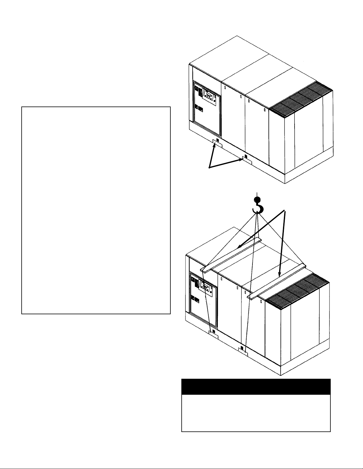
1.2 UNPACKING AND HANDLING
The compressor package has been mounted on a base
which provides for forklifting between the two side
channels to facilitate handling during shipment. Care in
positioning the forklifts is important because the location
of the center of gravity is strongly affected by the location
of the compression module and drive motor.
Slings can be used to lift the crates, but spreader bars
must be used to prevent the slings from exerting a force
against the sides of the crates.
1.3 TOOLS
Remove compressor unit from wooden skid.A crowbar
and hammer will be needed.
IMPORTANT
READ THIS
LOST OR DAMAGED GOODS
THOROUGHLY INSPECT THIS SHIPMENT
IMMEDIATELY UPON ARRIVAL
OUR RESPONSIBILITY FOR THIS SHIPMENT
CEASED WHEN THE CARRIER SIGNED
BILL OF LADING
If goods are received short or in damaged condition, it is important that
you notify the carrier and insist on a notation of the loss or damage
across the face of the freight bill.Otherwise no claim can be enforced
against the transportation company.
If concealed loss or damage is discovered, notify your carrier at once
and request an inspection.This is absolutely necessary.Unless you do
this the carrier will not entertain any claim for loss or damage.The agent
will make an inspection and grant a concealed damage notation.If you
give the transportation company a clear receipt for goods that have been
damaged or lost in transit, you do so at your own risk and expense.
WE, AT I-R, ARE WILLING TO ASSIST YOU IN EVERY POSSIBLE
MANNER TO COLLECT CLAIMS FOR LOSS OR DAMAGE, BUT THE
WILLINGNESS ON OUR PART DOES NOT MAKE US RESPONSIBLE
FOR COLLECTION OF CLAIMS OR REPLACEMENT OF MATERIAL.
THE ACTUAL FILING AND PROCESSING OF THE CLAIM IS YOUR
RESPONSIBILITY.
Ingersoll-Rand Company
Davidson, North Carolina
APDDGFO-99-79
Before starting this air compressor unit, the
shipping brace(s) must be removed.
Save the brace(s) for future use.
IMPORTANT
See tag in unit.
FORKLIFT PADDING
WILL REDUCE SCRATCHES
AND MARS
SPREADER
BARS
Page 11
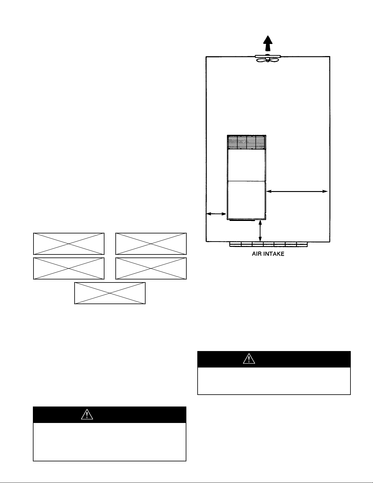
2.0 INSTALLATION
2.1 VENTILA TION
Oil flooded rotary air compressors produce large
amounts of heat. Because of this large heat production,
the compressor must be placed in a room with adequate
ventilation.
If heated air from the compressor exhaust is allowed to
recirculate back to the compressor, the compressor will
overheat and shut down.This heat must be exhausted
from the room.You should take this into consideration
when you decide where to place the compressor within
your plant. Consider that the required maintenance
clearance is 3 ft (.9 m) all around the compressor.
However 42” (1.06m), or minimum required by latest NEC
or applicable local codes, must be maintained in front of
control panel.
Ambient temperatures higher than 115°F (46°C)
should be avoided as well as areas of high humidity.
Consider also the environment surrounding or near
the compressor.The area selected for the location of
the compressor should be free of dust, chemicals,
metal filings, paint fumes and overspray.
2.2 FOUNDATION REQUIREMENTS
Refer to the foundation plan for the particular model
compressor to be installed. See Section 8.0.
The compressor can be installed on any level floor that is
capable of supporting it. Compressor weights are listed
on the foundation plans.
When sound transmission is of particular impor tance it is
often helpful to install a sheet of rubber-fabric-matting, or
cork under the compressor to reduce the possibility of
resonant sounds being transmitted or amplified through
the floor.
2.3 PIPING
The use of plastic bowls on line filters without metal
guards can be hazardous.Their safety can be affected by
either synthetic lubricants or the additives used in mineral
oil. From a safety standpoint, metal bowls should be used
on any pressurized system. Review of your plant air line
system is recommended.
The built-in aftercooler reduces the discharge air
temperature well below the dew point (for most ambient
conditions), therefore, considerable water vapor is
condensed.To remove this condensation, each
compressor with built-in aftercooler is furnished with a
combination condensate separator/trap.
DUST CHEMICALS
METAL
FILINGS
PAINT
SPRAY
OVERSPRAY
Do not use plastic pipe, soldered copper
fittings or rubber hose for discharge piping.
W ARNING
Never elevate the compressor unit
above the floor level.This may allow air
to enter the cabinet under the base.
Performance will be affected.
NOTICE
9
36”
(.9 m)
36” (.9 m)
42” (1.06m) OR
CODE MINIMUM
Page 12
10
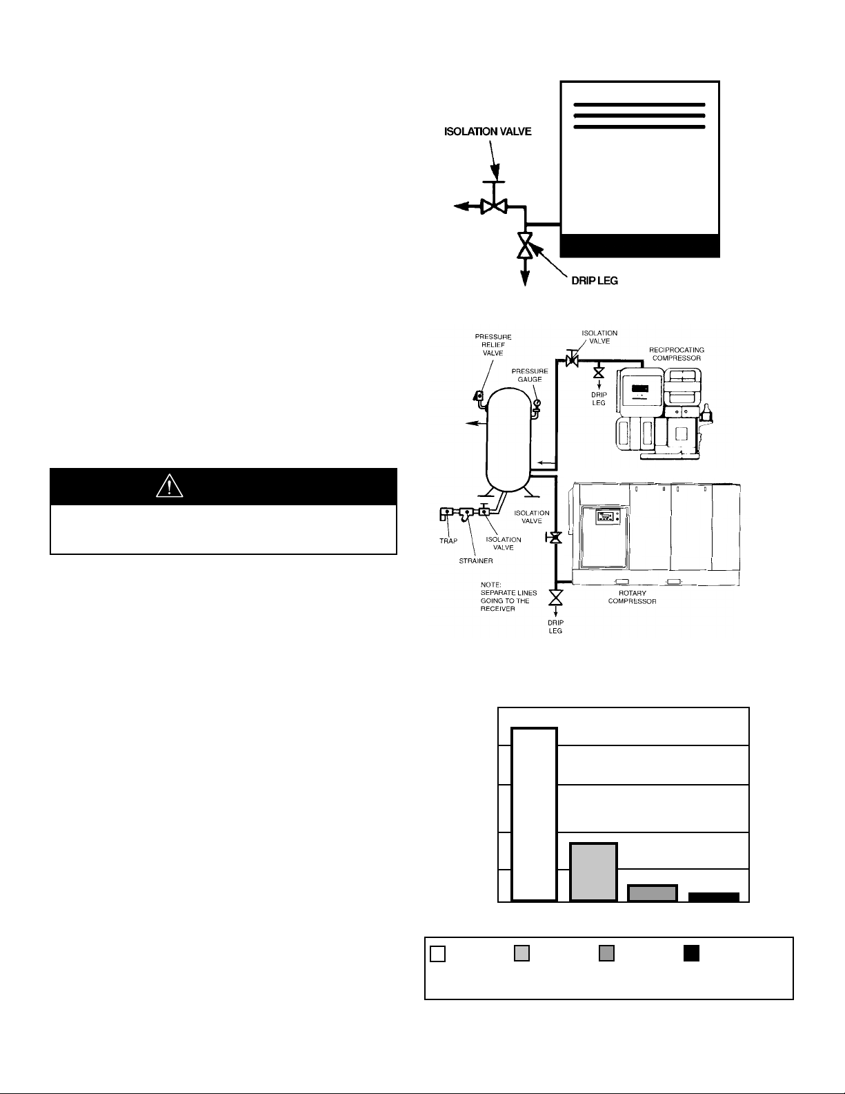
DISCHARGE PIPING WITH AFTERCOOLER
ROTARY-RECIP IN PARALLEL
Do not use the compressor
to support the discharge pipe.
Careful review of piping size from the compressor
connection point is essential. Length of pipe, size of pipe,
number and type of fittings and valves must be
considered for optimum efficiency of your compressor.
It is essential when installing a new compressor to review
the total plant air system.This is to ensure a safe and
effective total system.
Liquid water occurs naturally in air lines as a result of
compression. Moisture vapor in ambient air is
concentrated when pressurized and condenses when
cooled in downstream air piping.
Moisture in compressed air is responsible for costly
problems in almost every application that relies on
compressed air.Some common problems caused by
moisture are rusting and scaling in pipelines, clogging of
instruments, sticking of control valves, and freezing of
outdoor compressed air lines. Any of these could result in
partial or total plant shutdown.
Compressed air dryers reduce the water vapor concentration and prevent liquid water formation in
compressed air lines. Dryers are a necessary companion
to filters, aftercoolers, and automatic drains for improving
the productivity of compressed air systems.
NOTICE
2.3 PIPING (Continued)
A dripleg assembly and isolation valve should be
mounted near the compressor discharge. A drain line
should be connected to the condensate drain in the
base.
IMPORTANT :The drain line must slope downward from
the base to work properly.
NOTE: For ease of inspection of the automatic drain trap
operation, the drain piping should include an open funnel.
It is possible that additional condensation can occur if the
downstream piping cools the air even further and low
points in the piping systems should be provided with
driplegs and traps.
IMPORTANT :Discharge piping should be at least as
large as the discharge connection at the compressor
enclosure. All piping and fittings must be suitable for the
maximum operating temperature of the unit and, at a
minimum, rated for the same pressure as the compressor
sump tank.
MOISTURE CONTENT OF COMPRESSED AIR
200
160
120
80
40
0
DEW POINT
without
Aftercooling
100°F/38°C
(with
Aftercooler)
35°F /1.7°C
(Refrigerated
Dryer)
-40°F/-40°C
(Desiccant
Dryer)
Gallons of Water/24
hours/1000 acfm
Page 13

11
2.4 ELECTRICAL INSTALLATION
Before proceeding further, we recommend that you
review the safety data in the front of this manual.
Locate the compressor data plate on the side of the
cooler box or end of the unit.
The data plate lists the rated operating pressure, the
maximum discharge pressure and the electric motor
characteristics and power.
Confirm that the line voltage and compressor nameplate
voltage are the same and that the standard starter box
meets the intent of NEMA 1 guidelines.
Open the starter box door.Confirm that all electrical
connections are made and tightened. Confirm that the
control transformer is wired correctly for supply voltage.
See Figure 2.4-1 on next page for typical control
transformer wiring.
Two types of dr yers, refrigerated or desiccant, are used
to correct moisture related problems in a compressed air
system. Refrigerated dryers are normally specified where
compressed air pressure dew points of 33°F (1°C) to
39°F (4°C) are adequate. Desiccant dryers are required
where pressure dew points must be below 33°F (1°C).
Contact your local Ingersoll-Rand distributor for
assistance in selecting correct Ingersoll-Rand filtration or
drying products.
NOTE: Screw type compressors should not be installed
in air systems with reciprocating compressors without a
means of pulsation isolation, such as a common receiver
tank.We recommend both types of compressor units be
piped to a common receiver utilizing individual air lines.
When two rotary units are operated in parallel, provide an
isolation valve and drain trap for each compressor before
the common receiver.
ROTARY TWO COMPRESSOR SYSTEM
PRESSURE
RELIEF
VALVE
PRESSURE
GAUGE
54425996 Rev. C (75-160 KW)
39557095 Rev.05 (100-200 HP)
COMPRESSOR MODEL...............................
CAPACITY......................................................
RATED OPERATING PRESSURE.................
MAX. DISCHARGE PRESSURE...................
MAX. MODULATE PRESSURE.....................
NOMINAL DRIVE MOTOR............................
NOMINAL FAN MOTOR................................
TOTAL PACKAGE AMPS...............................
VOLTS............................................................
PHASE / HERTZ............................................
CONTROL VOLTAGE.....................................
SERIAL NUMBER..........................................
CONTACTOR AMP. RATING.....................................
ASSEMBLY AMP. RATING........................................
LOCKED ROTOR AMP. RATING OF ASSY. ............
DAVIDSON, NORTH CAROLINA 28036
WWW.AIR.INGERSOLL-RAND.COM
COMPRESSOR MODEL...............................
CAPACITY......................................................
RATED OPERATING PRESSURE.................
MAX. DISCHARGE PRESSURE...................
MAX. MODULATE PRESSURE.....................
NOMINAL DRIVE MOTOR............................
NOMINAL FAN MOTOR................................
TOTAL PACKAGE AMPS...............................
VOLTS............................................................
PHASE / HERTZ............................................
CONTROL VOLTAGE.....................................
SERIAL NUMBER..........................................
CONTACTOR AMP. RATING.....................................
ASSEMBLY AMP. RATING........................................
LOCKED ROTOR AMP. RATING OF ASSY. ............
DAVIDSON, NORTH CAROLINA 28036
WWW.AIR.INGERSOLL-RAND.COM
Compressor Package Data
AIR SOLUTIONS GROUP
Compressor Package Data
AIR SOLUTIONS GROUP
m3/MIN
BARG
BARG
BARG
KW
KW
54425996 Rev.C
CFM
PSIG
PSIG
PSIG
H.P.
H.P.
39557095 Rev.05
Page 14
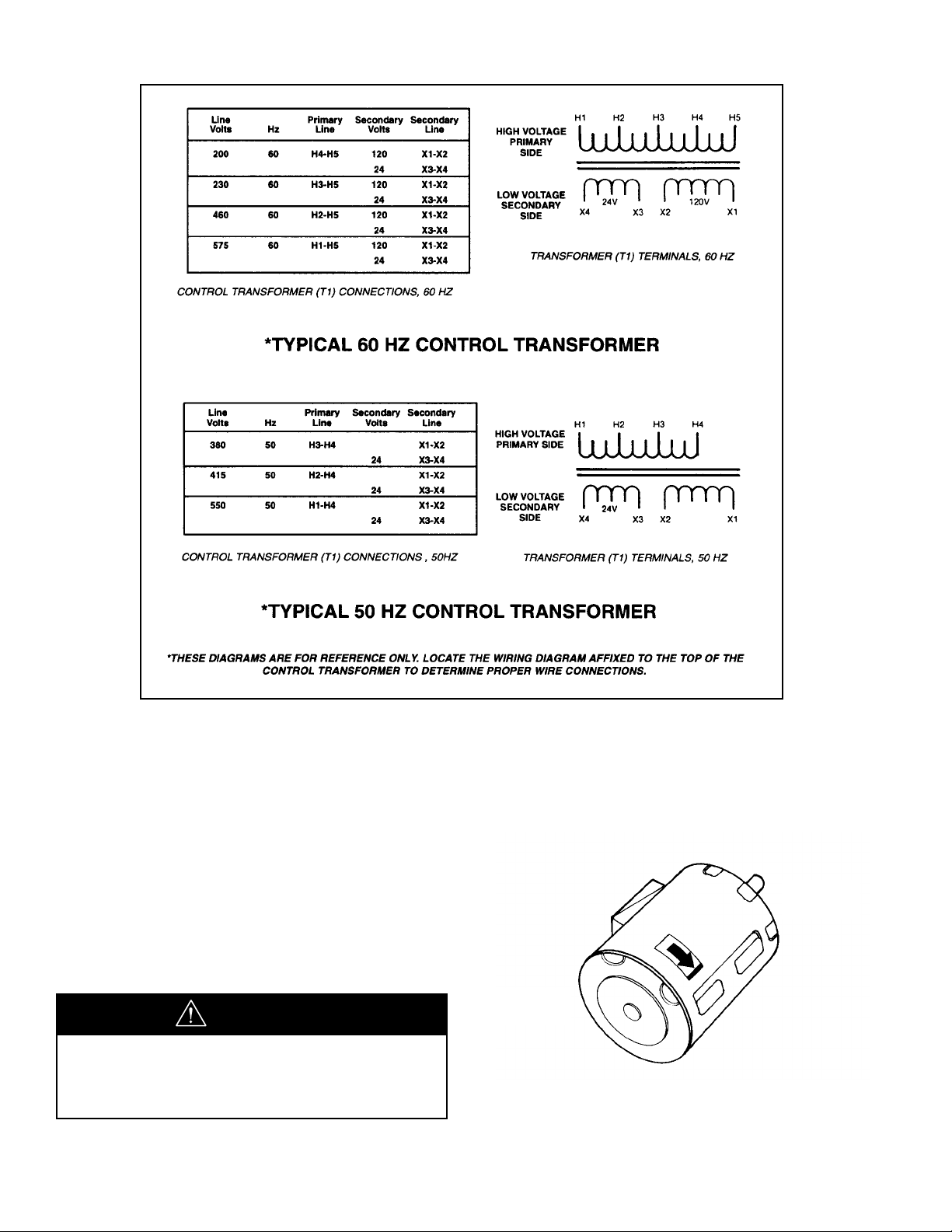
If the compressor is operated in the
opposite direction of rotation, airend damage
can result and is not warrantable.
CAUTION
12
ELECTRICAL INSTALLATION (Continued)
Inspect the motor and control wiring for tightness.
Close and fasten the starter box door.
ROTATION CHECK
Locate the rotation decal on each motor.
DRIVE MOTOR
The correct compressor drive motor rotation is
clockwise when viewed from the rear or non-drive
end of the motor.See Figure 2.4-2.
FIGURE 2.4-2 DRIVE MOTOR ROTATION
FIGURE 2.4-1 TYPICAL CONTROL TRANSFORMER WIRING
DRIVE
END
NON-DRIVE
END
110
110
110
110V
Page 15
13
ELECTRICAL INSTALLATION (Continued)
The Intellisys will automatically shut the unit down if the
compressor rotation is incorrect, and the display will
indicate “CHECK MOTOR ROTATION” and will flash
“ALARM”.
For the compressor motor rotation check, the motor
jogging time must be as short as possible.
After depressing the start button, IMMEDIATELY
depress the “EMERGENCY STOP”button. Should the
motor rotation be incorrect, put main disconnect in
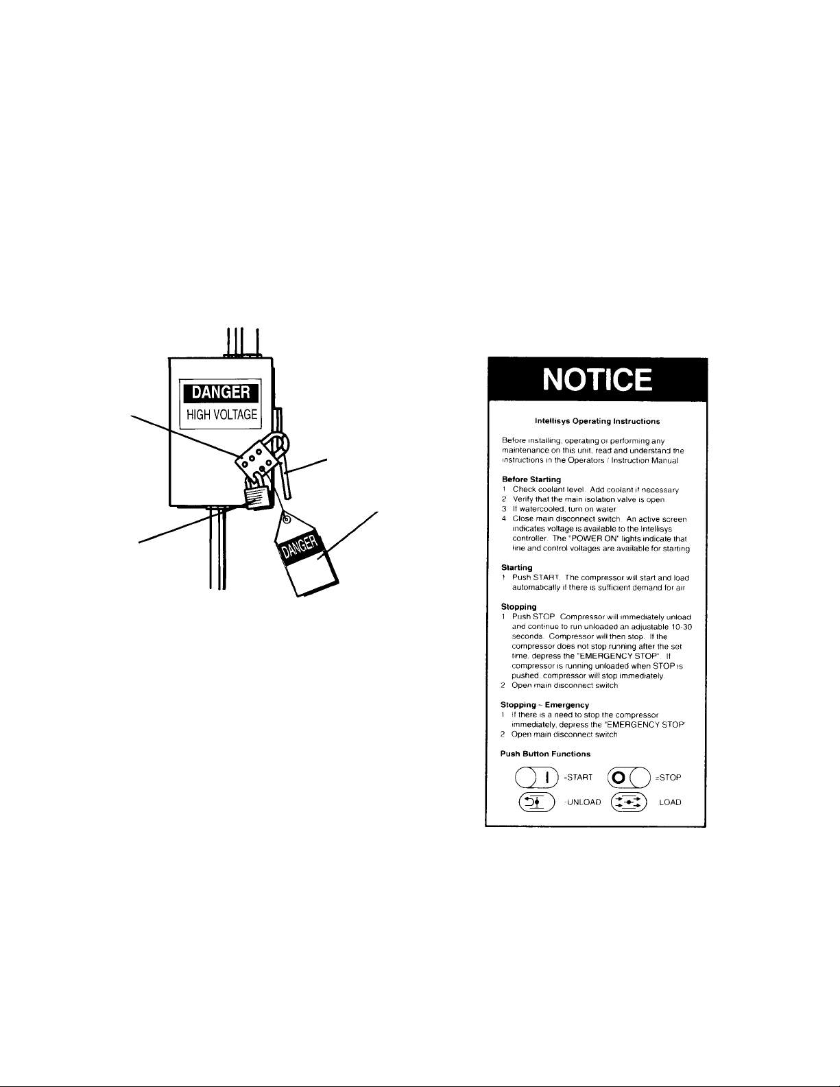
the OFF position, lock and tag. See Figure 2.4-3.
Fan motor rotation is clockwise when viewed from
the fan motor side.
INTELLISYS OPERATING INSTRUCTIONS
Read and understand the following Intellisys Operating
Instructions (See Figure 2.4-4) prior to operating the unit.
NOTE: These instructions are also contained on
the decal near the Intellisys panel of the unit.
FIGURE 2.4-3 MAIN DISCONNECT
LOCKED AND TAGGED
Open the starter box door.
Interchange any two line connections (L1, L2 or L3) at
the starter. Close and fasten the starter box door.
Recheck for correct rotation.
FAN MOTOR
Observe the compressor cooling fan.The rotation should
be in accordance with the fan rotation decal affixed to the
fan motor. Cooling air should exhaust through fan end of
compressor enclosure.
Should the motor rotation not be correct, put the main
disconnect in the OFF position, lock and tag.
Interchange any two fan motor leads at the fan motor
manual starter (MMS). Close and fasten the starter box
door.Recheck for correct rotation.
HASP
KEY
LOCK
LEVER
TAG
FIGURE 2.4-4 INTELLISYS
OPERATING INSTRUCTIONS
Page 16

14
2.5 OUTDOOR SHELTERED INSTALLATION
Many times a compressor must be installed outside due
to jobsite conditions or limited space within a
manufacturing facility. When this occurs there are certain
items that should be incorporated into the installation to
help ensure trouble free operation.These items have
been listed below plus Figure 2.5-1 has been included to
show a typical outdoor sheltered installation.The unit
must be purchased with the Outdoor Modification Option
to provide NEMA 4 electrics and a cabinet exhaust on
the end of the unit rather than the top to prevent recirculation of cooling air.
■ The compressor should be on a concrete pad
designed to drain water away.If the concrete pad is
sloped, then the compressor must be leveled.In order
to properly pull cooling air through the aftercooler, the
base/skid must be sealed to the concrete pad.
■ The roof of the shelter should extend a minimum of
4 ft (1.2 m) around all sides of the compressor to prevent direct rain and snow from falling on the unit.
■ Air-cooled machines must be arranged under the
shelter in a way that prevents air recirculation (i.e.hot
exhaust back to the package inlet).
■ If the installation includes more than one compressor,
the hot air exhaust should not be directed towards the
fresh air intake of the second unit or an Air Dryer.
■ If a standard machine is to be installed outside, the
ambient temperature must never drop below 35°F
(1.7°C).
■ If ambient temperature drops below 35°F (1.7°C) to as
low as –10°F (–23°C) the unit must be supplied with
the Low Ambient Option. Installations below –10°F
(–23°C) ambient are not recommended.The Low
Ambient Option requires a separate power source to
operate internal heaters.
■ Arrange the machine with the Intellisys con-
troller/starter enclosure facing away from the sun as
radiant heat can affect starter/lntellisys performance.
Also direct sunlight and UV rays will degrade the
membrane touch panel.This is not a warrantable
situation.
■ Power disconnect switch should be within line of sight
and in close proximity to the unit.N.E.C.and local
electrical codes must be followed when installing the
power disconnect switch.
■ Condensate drains must never be allowed to dump on
the ground. Run to a suitable sump for future
collection and disposal or separation of lubricant and
water mixture.
■ Incoming power connections must use suitable
connectors for outdoor weather tight service.
■ A minimum of 3 ft (.9 m) clearance must be allowed
on all four sides of the unit for service access.If
possible, access by a forklift and/or an overhead beam
hoist should be kept in mind (for eventual service to
airend or motor).
■ If the area around the installation contains fine
airborne dust or lint and fibers etc., then the unit
should be purchased with the High Dust Filter Option
and TEFC motors.
■ If larger debris, such as leaves or trash, are blowing in
the area, the Inlet Panel Filter Accessory should be
purchased and added to the unit (ship loose item).
■ Some type of protection such as a fence or security
system, should be provided to prevent unauthorized
access.
Page 17
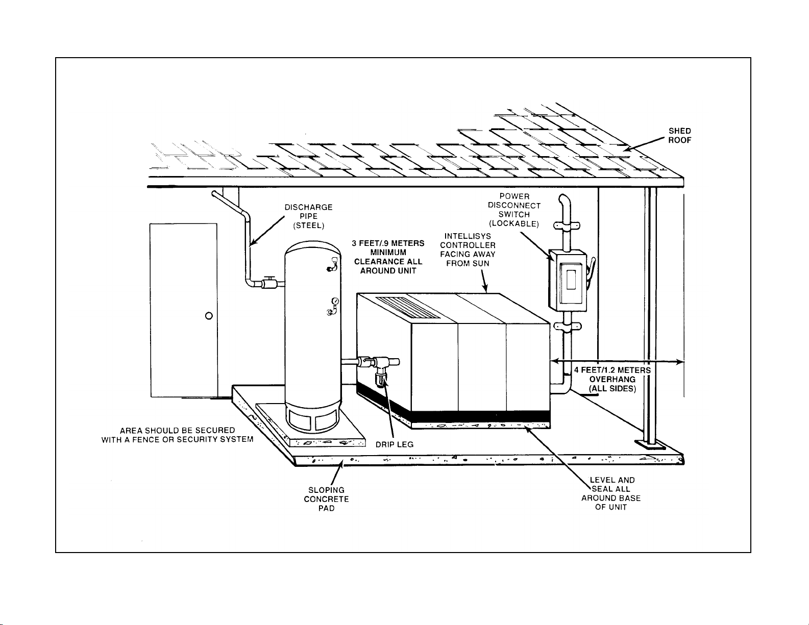
FIGURE 2.5-1 TYPICAL OUTDOOR SHELTERED INSTALLATION
15
Page 18
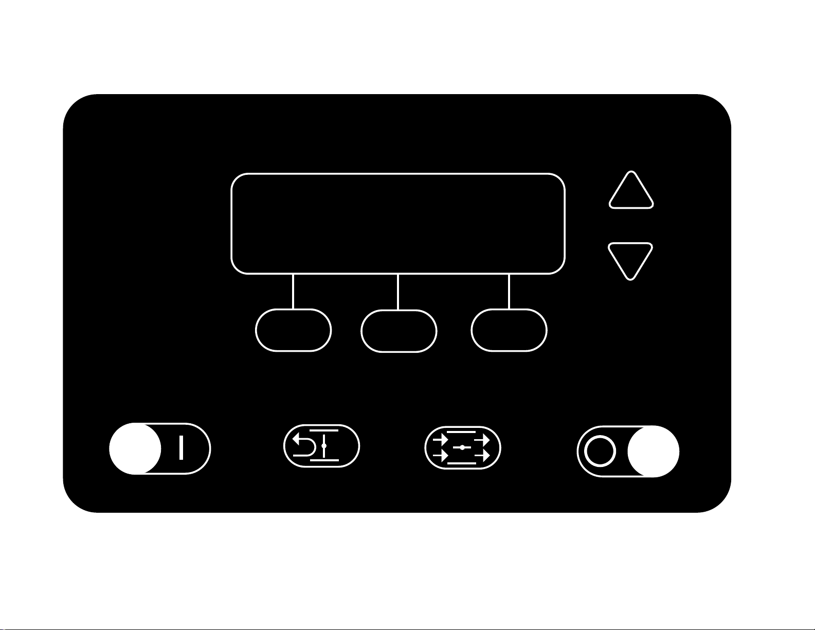
16
3.0 INTELLISYS
INTELLISYS CONTROLLER
INGERSOLLrAND
INTELLISYS
Page 19
3.0 INTELLISYS
3.1 INTELLISYS CONTROLS
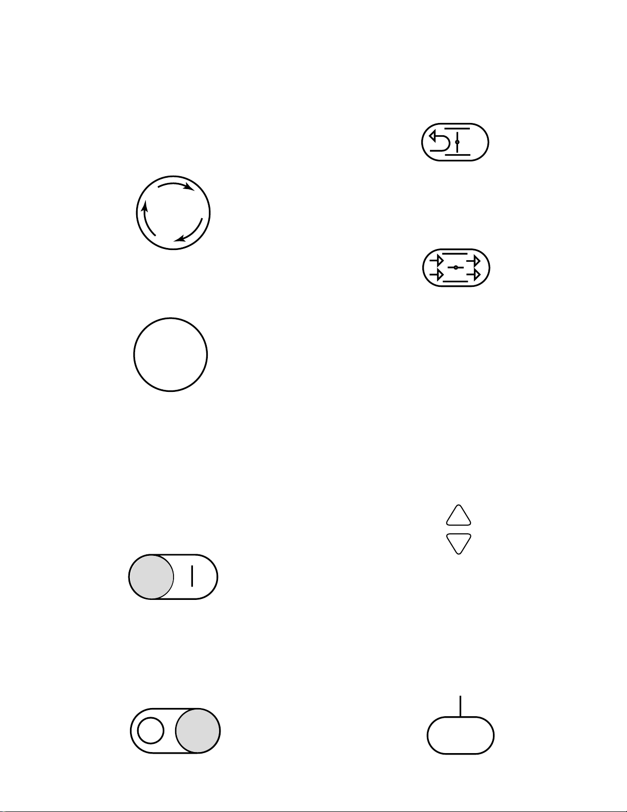
EMERGENCY STOP
Pressing this switch stops the compressor immediately.
The compressor can not be restarted until the switch is
manually reset.Turn the switch knob clockwise to
reset.
POWER ON LIGHT
This indicates the control voltage and the line voltage
are available for starting.
The operator panel is divided into two areas.The
bottom row of four buttons provides direct control over
the starting, stopping, unloading and loading of the
compressor.These are defined by the symbols printed
on the buttons themselves, as shown here.
START
Pressing this button will start the compressor if the
display shows “Ready To Start”. The compressor will
start and load if there is sufficient demand for air.
STOP
Pressing this button will activate the unloaded stop
sequence. If the compressor is running loaded, it will
unload and continue to run unloaded for an adjustable
10 to 30 seconds and then stop.If the compressor is
running unloaded, it will stop immediately.
UNLOAD
Pressing this button will cause the compressor to
unload and remain unloaded.The display will indicate
the machine is “Running Unloaded”, and “Mode:
UNLOAD”.
LOAD
Pressing this button will cause the compressor to load
if the compressor is running and if the “Discharge
Pressure” is less than the “Online Pressure”. This also
returns the machine to the operating mode that is
specified by the “Mode of Operation”set point.
The other five buttons provide access to various
operator-selectable functions and machine operating
conditions.The pur pose of each of these buttons is
defined by the display screen and the particular
function being performed at that time.
ARROWS
These up and down buttons have multiple functions
relating to the right half of the display screen.When
lists are presented, the buttons are used to move up or
down through the items on the list.The small arrow(s)
displayed in the upper right corner of the display
screen indicate when you can move up (designated by
arrow head pointing up) and/or down (designated by
arrow head pointing down) through the list.
When the value of a specific machine operating
parameter is highlighted on the display screen for the
purpose of changing that value, the buttons are used
to change the value itself.
DISPLAY BUTTONS
The functions of the three buttons below the display
screen change and are defined by the words
immediately above them in the bottom line of the
screen. Each function, such as MAIN MENU, STATUS,
SET, etc., is descr ibed in appropriate sections in this
manual.
17
EMEG
STOP
POWER
ON
Page 20
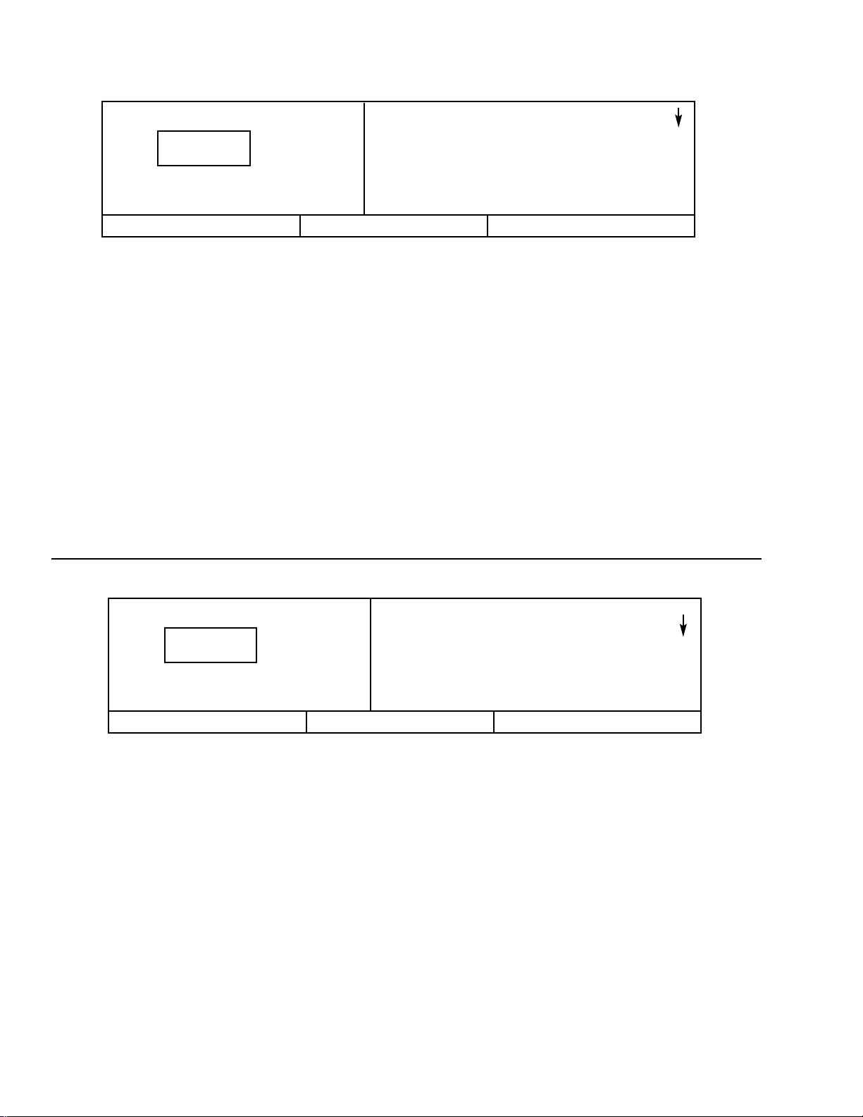
The display screen is divided into three functional
areas, as seen in the typical CURRENT STATUS
screen shown here.
The left side continuously shows the package
discharge pressure in large numbers, with the line
directly below the numbers showing the running
condition of the machine, and the line below that
showing the present mode of operation.
The right side shows various items or lists such as the
machine’s CURRENT STATUS readings, the MAIN
MENU, the OPERATOR SETPOINTS list, etc. Any of
the lists can be moved up or down by pressing the
arrow buttons to the right of the screen.The small
arrow(s) displayed in the upper right corner of the
screen indicate when you can move up (designated by
arrow head pointing up) and/or down (designated by
arrow head pointing down) through a list.The arrow
buttons are also used to change an individual item’s
value.At certain times, items and/or their values are
“highlighted”.This means they are displayed as light
characters on a dark background.
The bottom of the screen is divided into thirds with the
words in each small box showing the function of the
button directly beneath it.The words will change in
these boxes depending on what actions are permitted
at any particular time.The action resulting from
pressing each of these buttons is indicated in Figure
3.2.1, which can be used as a quick reference of how
to step the controller screen through any desired
function.
3.2 DISPLAY SCREEN
3.3 CURRENT STATUS
The CURRENT STATUS screen is considered the
“normal” display that the controller shows.
The following items and their present values can be
displayed on the right side of the screen by pressing
the up and down arrow buttons.
CURRENT STATUS Items
Discharge Temperature Inlet V acuum
Airend Discharge Temperature Inlet Filter
Injected Temperature Total Hours
Sump Pressure Loaded Hours
Separator Pressure Drop % Load Modulation
Unloaded Inlet Vacuum
Coolant Pressure
Time & Date
Coolant Filter Software Title
and V ersion
The controller automatically returns the display to this
CURRENT STATUS screen from other screens if no
buttons are pressed within 30 seconds.
The MAIN MENU screen can be accessed from the
CURRENT STATUS screen by pressing the MAIN
MENU button, identified by the words “MAIN MENU” in
the bottom line of the screen directly above the center
button.
Running Loaded
Mode: MOD/ACS
- CURRENT STATUS-
Package Discharge Temp
103°F
Airend Discharge Temp
193°F
MAIN MENU
Running Loaded
Mode: MOD/ACS
-CURRENT STATUS-
Package Discharge Temp
103°F
Airend Discharge Temp
193°F
MAIN MENU
18
1 0 0
P S I
1 0 0
P S I
Page 21
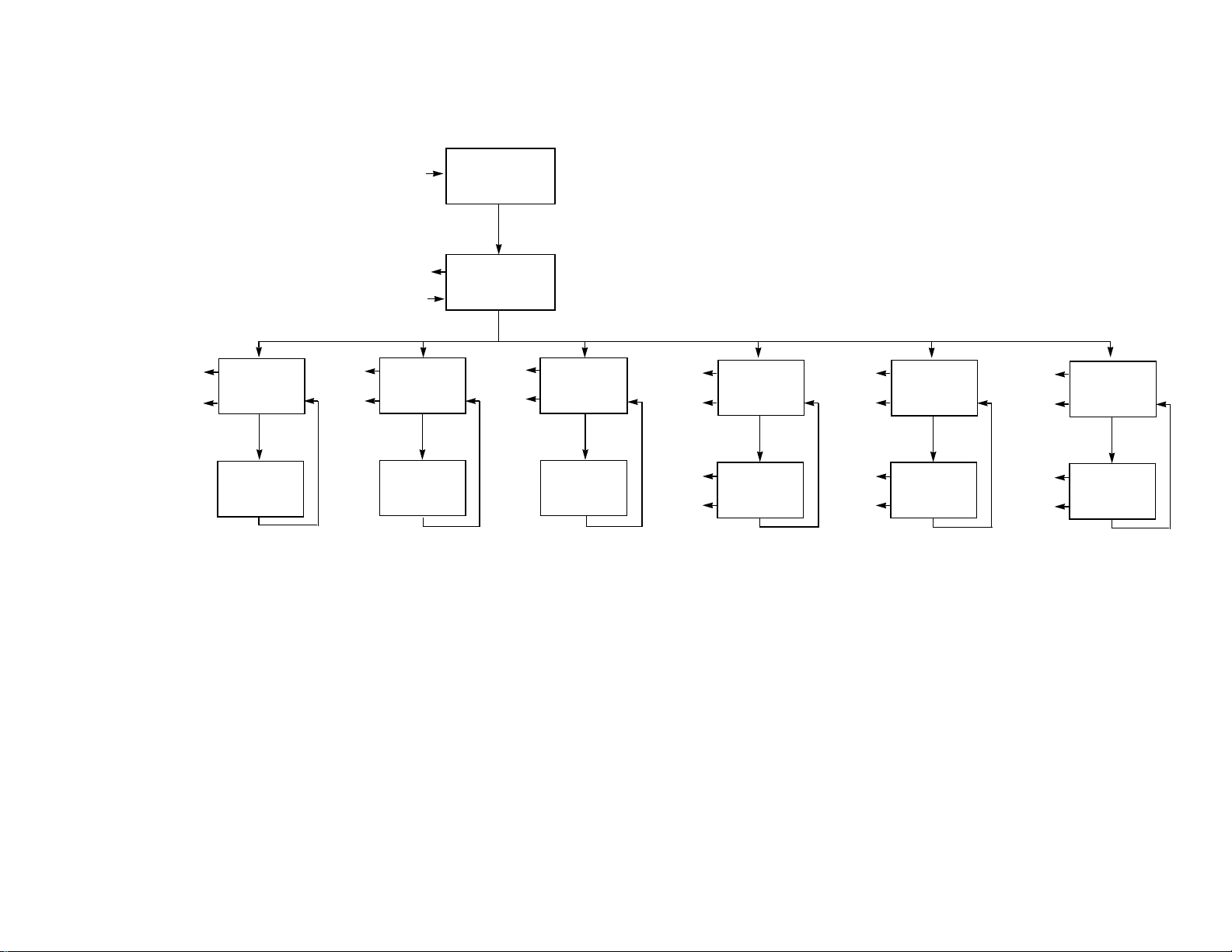
19
NOTE - Use the UP and DOWN arrows to move between selections.Items will be highlighted in inverse display mode.
* - Selecting the highlighted item will display the corresponding menu.
** - Selecting the highlighted item will place the value in edit mode.This is indicated by only the value being displayed in inverse display mode.
*** - The UP and DOWN arrows will alter the value. Depressing “Cancel” will exit the edit mode and leave the value unchanged. Depressing
“Set” will save the new value and flash the value to indicate acceptance.
**** - Depressing “Cancel” will exit calibration mode.Depressing “Calibrate” will calibrate selected sensor.
***** - Use UP and DOWN arrows to scroll through list of status items.
INTELLISYS
Operator Panel Flow Diagram
Figure 3.2.1
“Status”
“Alarm Hist.”
“Cancel ot Set”
“Cancel ot Set”
CURRENT STATUS
“Main Menu”
“Main Menu”
“Status”
OPERATOR
SETPOINTS**
“Select”
OPERATOR
SETPOINTS
ITEM***
“Cancel” or “Set” “Cancel” or “Set”
“Main Menu”
“Status”
“Status”
“Main Menu”
OPTIONS**
“Select” “Select”
OPTIONS
ITEM***
MAIN MENU*
“Select”
“Main Menu”
“Status”
CALIBRATION**
CALIBRATION
SENSOR
SENSOR
ITEM****
“Cancel” or “Calibrate”
“Main Menu”
“Status”
“Main Menu”
“Status”
ALARM
HISTORY**
“Select”
ALARM
HISTORY
ITEM*****
“Main Menu”
“Main Menu”
“Cancel” or “Set”
“Status”
“Status”
CLOCK
FUNCTIONS
“Select”
DATE AND
TIME
“Cancel” or “set”
“Main Menu”
“Status”
“Main Menu”
“Status”
INTEGRAL
SEQUENCING
“Select”
INTEGRAL
SEQUENCING
ITEM***
“Cancel” or “set”
Page 22
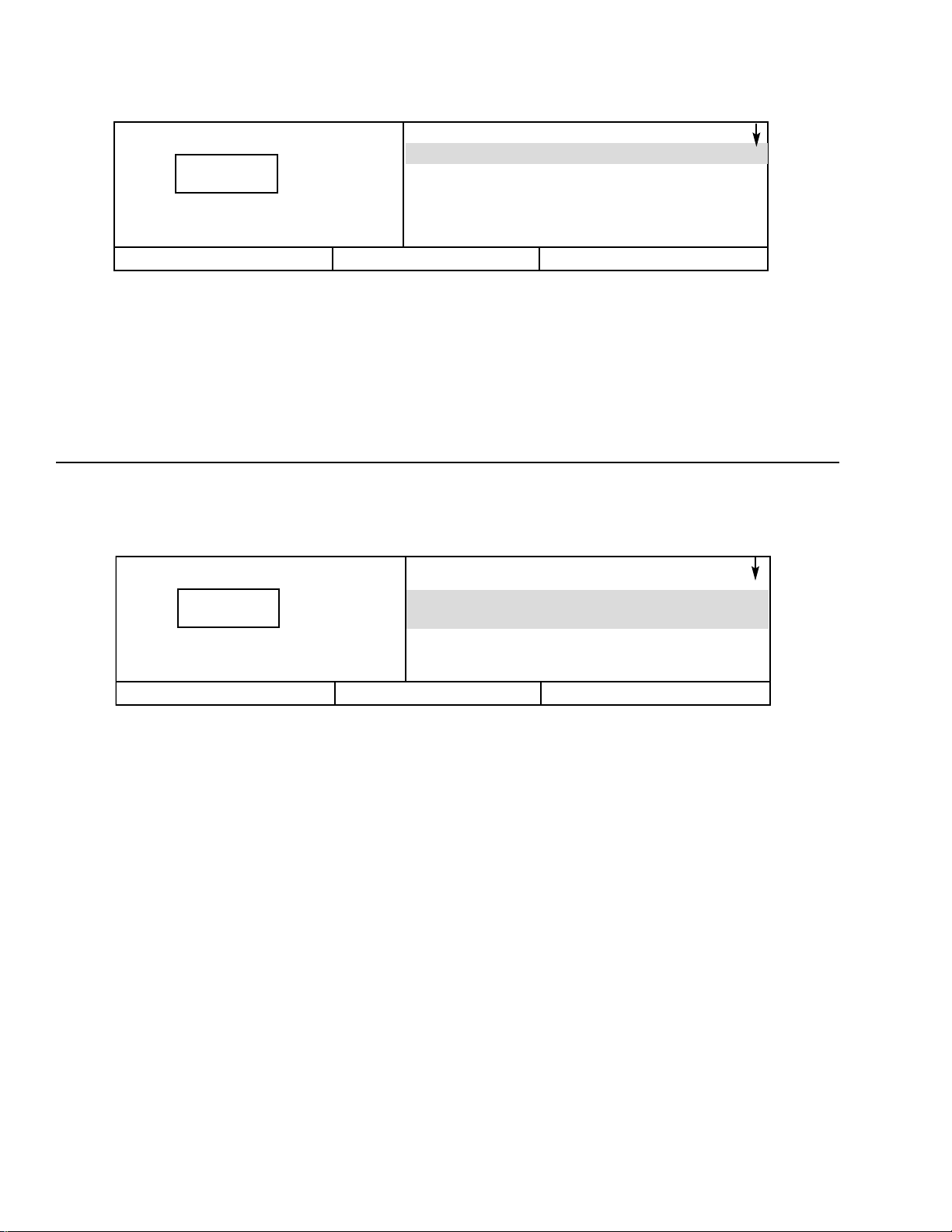
3.4 MAIN MENU
The MAIN MENU screen is the point from which
various operator functions can be accessed. Refer to
the reference diagram in Figure 3.2.1.
Each of the functions can be chosen by using the up
and down arrows to highlight it on the screen.
The controller will go to the highlighted function if the
SELECT button is pressed or will return to the
CURRENT STATUS screen if the STATUS button is
pressed.
STATUS
SELECT
Ready To Start
-MAIN MENUOperator Setpoints
Options
Sensor Calibration
Alarm History
Clock Functions
3.5 OPERATOR SETPOINTS
STATUS
MAIN MENU
SELECT
Ready To Start
-OPERATOR SETPOINTSOffline Pressure
103 PSI
Online Pressure
93 PSI
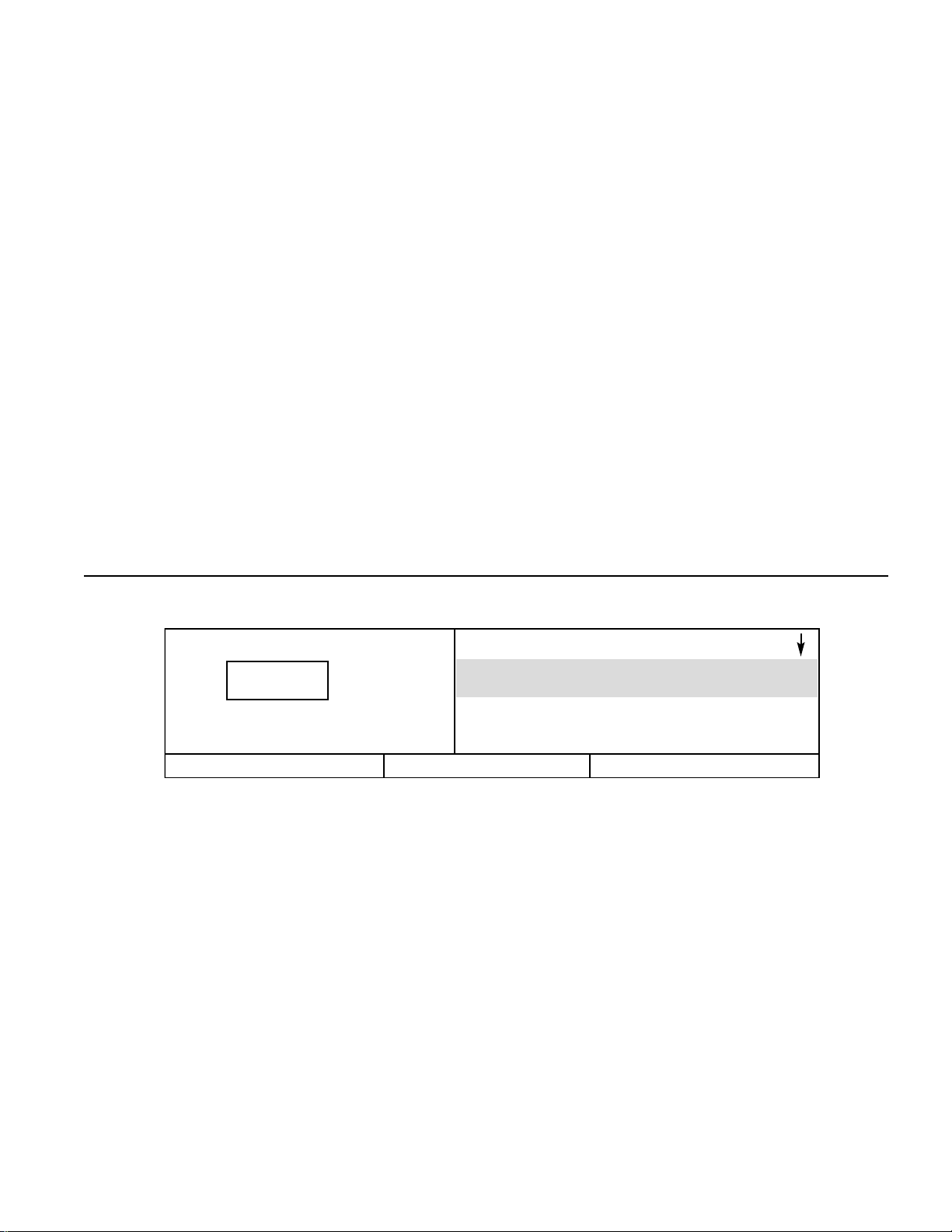
Setpoints are user-adjustable variables in the
controller logic that can be set using the OPERATOR
SETPOINTS screen.
The name and value of each of the setpoints listed
below can be seen on the screen by moving the list up
and down using the arrow buttons.
Setpoints associated with options are described in the
OPTIONS Section 3.6.
A setpoint’s value can be changed by first highlighting
the item and its value and pressing the SELECT
button to highlight just the value.When the value line is
highlighted by itself, the value can be adjusted using
the up and down arrow buttons.The CANCEL and
SET buttons appear at this time.Press the SET button
to enter the new value, or press the CANCEL button to
return to the value of the setpoint prior to using the
arrows.The displayed value will flash twice to indicate
it has been entered into the setpoint, and the pair of
setpoint item and value display lines will again be
highlighted together.
Operator set points can be exited by pressing the
STATUS or MAIN MENU buttons. If no buttons are
pressed within 30 seconds, the display will return to
the CURRENT STATUS screen.
OPERATOR SETPOINTS RANGE STEP UNIT
Lead/Lag Lead or Lag --- --Offline Pressure 75 to RATED +3 1 PSIG
Online Pressure 65 to OFFLINE - 10 1 PSIG
Lag Offset 0 to 45 1 PSIG
Mode of Operation MOD/ACS, ON/OFF LINE, --- ---
MODULATION ONLY
Max Modulation Pressure
Online + 10 to Offline + 7 1
PSIG
Stop Delay Time 10 to 60 1 SEC
Star-Delta Time* 5 to 20 1 SEC
(Screen) Contrast 0 to 10 1 ---
* Does not apply to automatic across the line starters.
20
1 0 0
P S I
1 0 0
P S I
Page 23
3.5.1 Lead/Lag- This setpoint is used for setting lead
or lag operation. If set to lead, the controller will load
and unload the compressor by the online and offline
setpoints. If set to lag, the controller will subtract the
lag offset (see 3.5.4) from the online and offline set
points and operate the compressor at the lower
pressure range.
3.5.2 Offline Pressure- This setpoint is the pressure
the compressor will unload at if it is operating in on/off
line mode.
3.5.3 Online Pressure- This setpoint is the pressure
the compressor will load at.
3.5.4 Lag Offset- This setpoint is used with the
lead/lag operation. If the lead/lag set point is set to lag
(see 3.5.1), the value of the lag offset will be
subtracted from the online and offline setpoints.
3.5.5 Mode of Operation- This setpoint is used to
select the operating mode of the compressor.The
choices are MOD/ACS, ON/OFF LINE, and
MODULATION ONLY. See section 5.8 for more
information on these operating modes.
3.5.6 Max Modulation Pressure- This setpoint is the
pressure the compressor will unload at if it is
modulating. As the package discharge pressure rises
toward this value, the inlet valve will start to close.The
compressor will unload once the package discharge
reaches this value. See section 5.8 for more
information on modulation.
3.5.7 Stop Delay Time- This setpoint is the minimum
amount of time the compressor will run unloaded
before stopping.This period does not apply to alar ms
(shutdowns).
3.5.8 Star-Delta Time- This setpoint is only used with
star-delta starters. It is not used if the starter is full
voltage or a remote starter.This is the time period
between starting and star-delta transition.
3.5.9 Contrast- This setpoint is used to improve the
display on the Intellisys.
-OPTIONS-
Auto Restart
Off
Auto Restart Time
10 MINUTES
3.6 OPTIONS
Options are turned on or off and their associated
values are set using the OPTION screen.
Some options require additional machine hardware
and the proper “Option Module” to plug into the
Intellisys controller.Descriptions of the options
operations are in Section 7.0.The name and value of
each of the options listed in the right hand column can
be seen by moving the list up and down using the
arrow buttons.
An Option item’s value can be changed the same way
OPERATOR SETPOINTS values are changed. See
Section 3.5 for an explanation.
OPTIONS ITEMS RANGE STEP UNIT
Auto Restart On/Off --- --Auto Restart Time 2 to 60 1 MIN
Auto Restart Delay Time 0 to 60 1 SEC
Sequencer On/Off --- --Remote Start/Stop On/Off --- --Power Out Restart On/Off --- --Power Out Restart Time 10 to 600 1 SEC
Low Ambient On/Off --- --Min. Cooler Out Temp
30 to 150 1 Deg. F
Separator Delta-P Solenoid On/Off --- --Separator Delta-P Sensor On/Off --- --Lead/Lag Cycle Length 0-750 1 HRS
Scheduled Start
00:00 to 23:59
1 TIME
Scheduled Stop
00:00 to 23:59
1 TIME
High Dust Filter On/Off --- --Modbus Protocol On/Off/ICU --- --Modbus Address 1 to 247 1 ---
STATUS
MAIN MENU
SELECT
Ready To Start
21
1 0 0
P S I
Page 24

22
3.6.1 Auto Restart- This setpoint is used to enable or
disable the auto restart option.
3.6.2 Auto Restart Time- This setpoint is the minimum
time period the compressor must run unloaded before
it can stop in the auto restart mode.
3.6.3 Auto Restart Delay Time- If the compressor is
stopped in auto restart, this setpoint is the number of
seconds the package discharge pressure must remain
below the online pressure setpoint before the
compressor will restart.
3.6.4 Sequencer- This setpoint is used to enable or
disable sequencer operation.
3.6.5 Remote Start/Stpop- This setpoint is used to
enable or disable the remote start/stop option.
3.6.6 Power Out Restart- This setpoint is used to
enable or disable the power out restart option, if it is
installed.
3.7.7 Power Out Restart Time- If the power out
restart option is installed and enabled, this setpoint is
time period between power returning to the
compressor and the compressor starting.
3.6.8 Low Ambient- This setpoint enables or disables
the low ambient option. If the low ambient option is
enabled, sensor 3CTT must be installed in the
compressor.
3.6.9 Minimum Cooler Out Temperature- When the
low ambient option is installed, this setpoint is the
minimum temperature to which the coolant must rise
before the compressor will load.
3.6.10 Separator Delta-P Solenoid- This setpoint
enables or disables the separator delta-p solenoid
option. Enabling this option will automatically disable
the Separator Delta-P Sensor option.
3.6.11 Separator Delta-P Sensor- This setpoint
enables or disables the separator delta-p sensor
option. Enabling this option will automatically disable
the Separator Delta-P Solenoid option.
3.6.12 Lead/Lag Cycle Length- This setpoint enables
the automatic cycling between lead and lag operation.
If it is set to a value greater than 0, the controller will
cycle between lead and lag operation.The value of this
set point is the cycle length in real time hours. A value
of 0 will disable the automatic cycling between lead
and lag.
3.6.13 Scheduled Start- If the scheduled start/stop
option is installed, this set point is the time of the day
(hour and minute) that the compressor will
automatically start. To disable this option, set it to the
same value as the scheduled stop (section 3.6.14).
3.6.14 Scheduled Stop- If the scheduled start/stop
option is installed, this setpoint is the time of the day
(hour and minute) that the compressor will
automatically stop.To disable this option, set it to the
same value as the scheduled start (section 3.6.13).
3.6.15 High Dust Filter- This option enables or
disables the high dust filter operation.
3.6.16 Modbus Protocol- This option is for IngersollRand service use only.
3.6.17 Modbus Address- This feature is used with the
Modbus Protocol and is for Ingersoll-Rand service use
only.
3.6 OPTIONS (CONTINUED)
Page 25
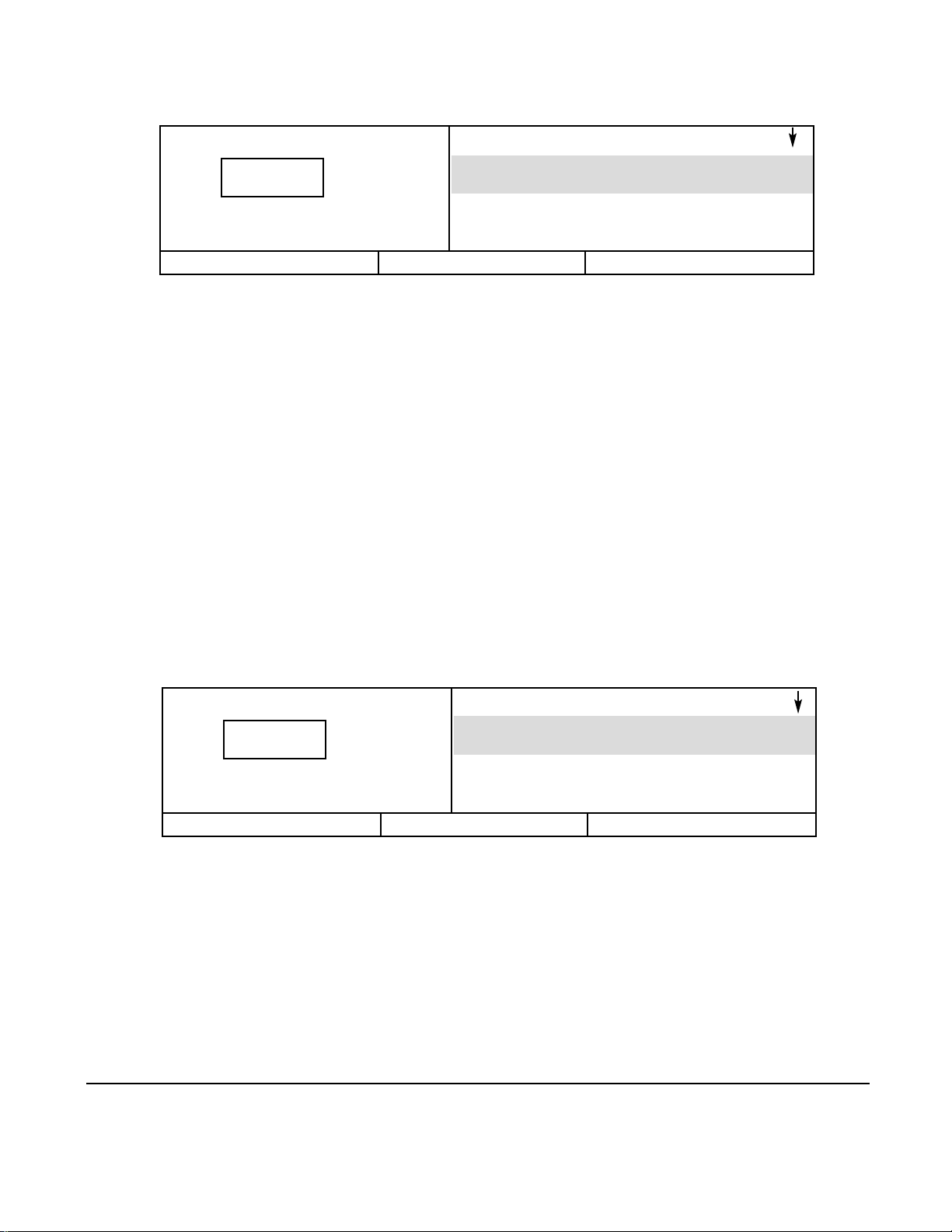
3.7 SENSOR CALIBRATION
-SENSOR CALIBRATIONSensor 1AVPT
CALIBRATE
Sensor 3APT
CALIBRATE
STATUS
MAIN MENU
SELECT
Ready To Start
Pressure sensor calibration is done through the
SENSOR CALIBRATION screen. Sensor calibration
can only take place when the machine is stopped.
Calibration needs to be done only after a sensor has
been replaced or the Intellisys controller has been
replaced.
Each of the sensors listed below can be chosen by
using the up and down arrow buttons to highlight it on
the screen.
SENSOR CALIBRATION Items
Sensor 1AVPT
Sensor 3APT
Sensor 4APT
Sensor 5CPT
Sensor 6APT
Select the highlighted sensor by pressing the SELECT
button. Press the CALIBRATE button to start the
automatic calibration procedure, or press the CANCEL
button to not calibrate it and return to the sensor list.
The calibration screen can be exited by pressing either
the STATUS or MAIN MENU buttons. If no buttons are
pressed within 30 seconds, the display will return to
the CURRENT STATUS screen.
0
23
-ALARM HISTORYAlarm History 1
MOTOR OVERLOAD
Alarm History 2
HIGH AIREND DISCH TEMP
3.8 ALARM HISTORY
STATUS
MAIN MENU
SELECT
Ready To Start
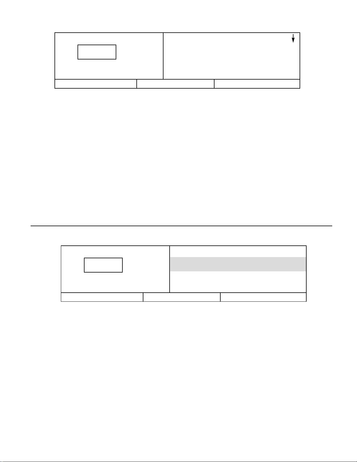
Alarm History displays each of the Alarm messages
for the last 15 Alarms experienced by the machine.It
also gives access to displaying the machine operating
conditions that existed at the time of each Alarm.The
first one shown, “Alarm History 1”, was the most
recent Alarm to occur. Note that multiple, consecutive
EMERGENCY STOP Alarms are not recorded as
separate Alarms, only the first one will be shown.
Each of the last 15 Alarm messages can be seen by
moving the Alarm History list up and down using the
arrow buttons.Pressing the SELECT button when one
of the Alarms is highlighted will display the list of
machine values that existed at the time that particular
Alarm occurred.
1 0 0
P S I
1 0 0
P S I
Page 26
24
-ALARM HISTORY 1-
Package Disch Pressure
199 PSI
Package Discharge Temp
103°F
STATUS
MAIN MENU
ALARM HISTORY
Ready To Start
The name and value of each of the items listed below
can be seen by moving the list up and down using the
arrow buttons.Pressing the ALARM HIST. button will
return the display to the ALARM HISTORY screen.
ALARM HISTORY Items
Discharge Pressure Coolant Filter
Discharge Temperature Inlet V acuum
Airend Discharge Temperature Inlet Filter
Injected Temperature Total Hours
Sump Pressure Loaded Hours
Separator Press. Drop % Load Modulation
Unloaded Inlet Vacuum
Coolant Pressure
Time & Date
Alarm histories can be exited by pressing either the
STATUS or MAIN MENU buttons. If no buttons are
pressed within 30 seconds, the display will return to the
CURRENT STATUS screen.
-CLOCK FUNCTIONSTime
01:15
Date
Jan 01, 00
3.9 CLOCK FUNCTIONS
The date and time for the real time clock is set through
the CLOCK FUNCTIONS screen. Use the up and
down arrows to highlight either TIME or DATE. Select
the highlighted setting by pressing SELECT.
If TIME is selected, first the hours will be highlighted.
Adjust the hours (00-23 hour clock) by using the up
and down arrows.Once the correct time is in the
display, press SET to highlight the minutes. Adjust the
minutes (00-59) and then press SET to complete
setting the time.
If DATE is selected, first the month will be highlighted.
Adjust the month by using the up and down arrows
and then press SET to highlight the date. Once the
correct date is displayed, press SET to highlight the
year. Once the correct year is displayed, press SET to
complete setting the date.
STATUS
MAIN MENU
SELECT
Ready To Start
1 0 0
P S I
1 0 0
P S I
Page 27
25
-INTEGRAL SEQUENCINGLead Compressor
Off
Total Compressors
2
3.10 INTEGRAL SEQUENCING
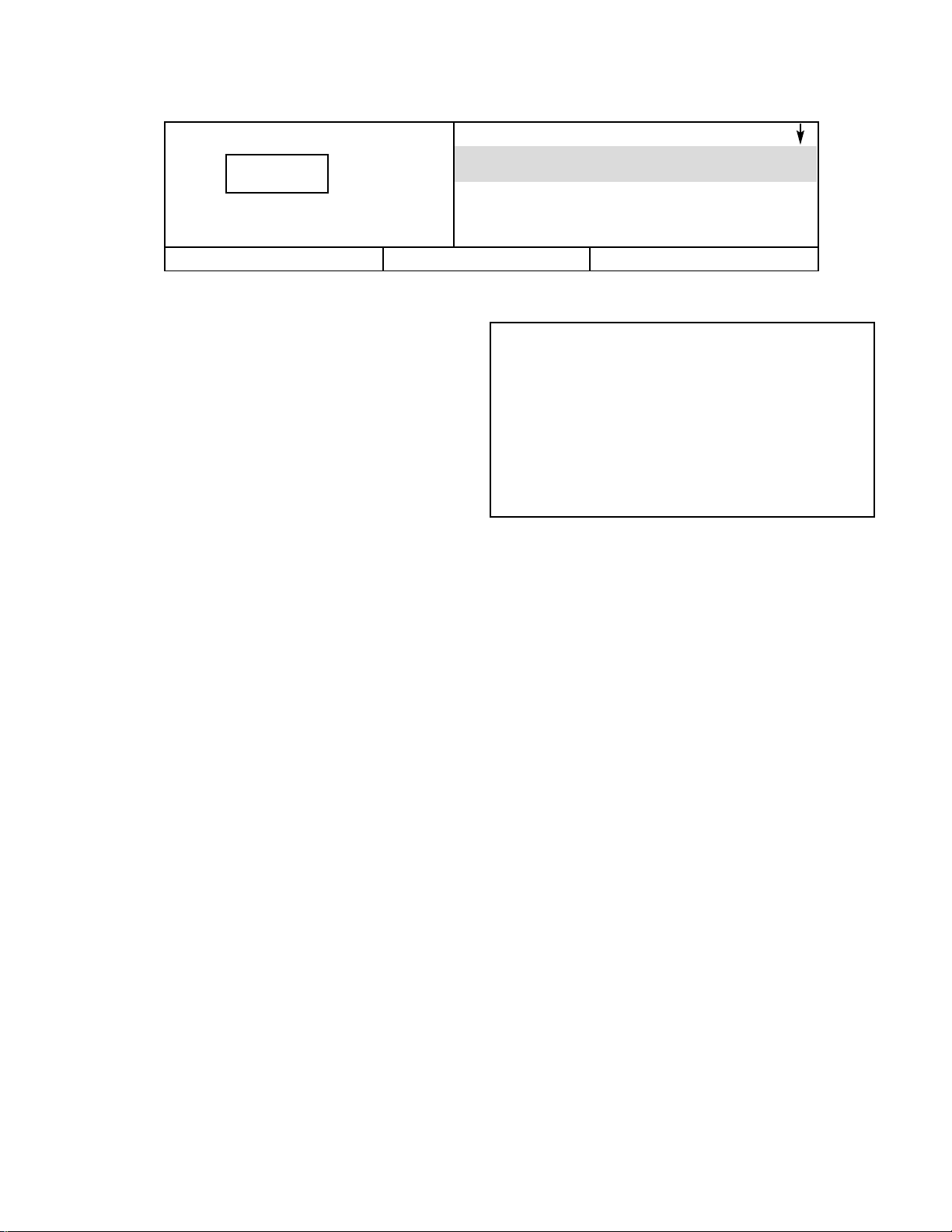
Integral Sequencing is set up using the INTEGRAL
SEQUENCING screen. A description of integral is in
section 7.0.The name and value of each of the
integral sequencing setpoints as listed in the right
hand column can be seen by moving the list up and
down using the arrow buttons.
3.10.1 Lead Compressor- The choices for this
setpoint are On, Off, Always, and Never. On, means
the compressor is the lead unit. Off, means the
compressor is not the lead unit, but it could become
the lead unit. If Always is selected, the compressor is
the lead unit and it will not transfer the lead to another
compressor.Never, means the compressor is not the
lead unit and will never become the lead unit.The
operator must set one unit (and only one) to On or
Always to start integral sequencing.
3.10.2 T otal Compressors- This is the total number of
compressors in the integral sequence.This setpoint
must be set to the same number on each compressor.
3.10.3 Compressor Address- This is the address of
the compressor in the integral sequence.No two
compressors can have the same address.Two
compressors with the same address will cause
communication failures.
3.10.4 Load Delay Time- This is the number of
seconds the lead compressor will wait for the package
discharge pressure to start rising after issuing a load
command to another compressor.If the package
discharge pressure has not started rising at the end of
this time period, the lead compressor will load the next
compressor in the sequencer.
3.10.5 Lead Change - Hours- This is the number of
hours the compressor will operate as the lead unit.
Once a compressor has operated as the lead for this
number of hours, it will transfer the lead to the next
compressor in the sequence.This setpoint does not
apply to a unit where the lead compressor is set to
always or never. If this setpoint is set to 0, the next 2
setpoints will determine when the lead is transferred.
3.10.6 Lead Change - Day & Lead Change - Time-
These two setpoints are used together.If the Lead
Change - Hours setpoint is set to 0, these two
setpoints will be used to determine when the
compressor will transfer the lead to the next
compressor in sequence. Lead Change - Day is the
day of the week that the compressor will transfer the
lead. Lead Change - Time is the time of the day that
the compressor will transfer the lead.
STATUS
MAIN MENU
SELECT
Ready To Start
INTEGRAL SEQUENCING RANGE STEP UNIT
Lead Compressor On/Off/Always/Never --- --Total Compressors 2 to 4 1 --Compressor Address 1 to Total Compressors 1 --Load Delay Time 10 to 60 1 SEC
Lead Change - Hours 0 to 750 1 HRS
Lead Change - Day Sun to Sat, Daily, Week
1
DAY
Day, Week End
Lead Change - Time 00:00 to 23:59 1 TIME
1 0 0
P S I
Page 28
Change Inlet Filter
Press RESET Twice
3.11 WARNINGS
STATUS
MAIN MENU
RESET
Running Unloaded
Mode: MOD/ACS
-CURRENT STATUS-
Package Discharge Temp
103°F
Airend Discharge Temp
193°F
WARNING
MAIN MENU
Running Unloaded
Mode: MOD/ACS
Pressing the WARNING button will return the display
to the WARNING screen and the RESET button.
A Warning needs to be reset by the operator by
pressing the RESET button twice.
The possible Warning messages are as follows.
AIREND DISCHARGE TEMP- This will occur if the
Airend Discharge (2ATT) exceeds 97% of the alarm
limit, 228°F (109°C), and is not adjustable.
CHANGE COOLANT FILTER- This warning will occur
if the high side pressure is 20 psig (1.4 bar) greater
than the low side pressure of 1 DPS, and the Injected
Coolant temperature (2CTT) is greater than
120°F (49°C).
CHANGE INLET FILTER- This will occur if the Inlet
Vacuum (1AVPT) is greater than 0.7 psig (.05 bar) and
the machine is fully loaded (inlet valve is completely
open).
CHANGE SEPR ELEMENT- This warning will occur if
the pressure on the Separator (3APT) is 12 psig
(.8 bar) greater than the pressure at the Package
Discharge (4APT), and the machine is fully loaded.
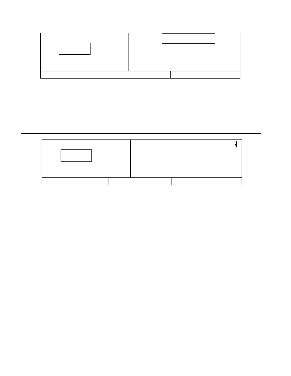
When a Warning occurs, a question mark will flash on
the display screen and appear in large letters as
shown above.The display message will indicate what
caused the warning.
If multiple Warnings exist, the small up/down arrows
will appear in the upper right corner of the display
screen.The multiple Warnings can be seen by
pressing the up and down arrow buttons.Pressing the
STATUS button will display the CURRENT STATUS
screen with the WARNING button indicating a Warning
still exists.
?
HIGH DISCHARGE PRESS- This can occur if the
machine’s loading function is being controlled by a host
device, such as a sequencer or an lSC.This warning
will occur when the package discharge pressure is
above the maximum offline pressure (rated pressure
plus 3 psig [.2 bar]) for more than 3 seconds.This
warning will cause the compressor to unload.The host
device will not be able to load the compressor until the
package discharge pressure falls to the rated pressure
of the machine.
SENSOR FAILURE 4ATT- This will occur if the
Package Discharge Temperature Sensor (4ATT) is
recognized as missing or broken.
AUXILIARY 1 (OR 2) - This warning will occur if either
of the auxiliary contacts closes.
HIGH SUMP/LINE DIF - This warning will occur if the
compressor is running loaded, the injected coolant
temperature is greater than or equal to 120 deg. F,
(49°C) the package discharge pressure is greater than
90 psig, (6.3 bar) the sump pressure is greater than the
compressor’s rated pressure, and the sump pressure is
25 psig (1.8 bar) or more above the package discharge
pressure.
26
1 0 0
1 0 0
P S I
P S I
Page 29
High Airend Disch Temp
229°F
Press RESET Twice
3.12 ALARMS
STATUS
MAIN MENU
RESET
STOPPED BY ALARM
Mode: MOD/ACS
-ALARM STATUS-
Package Disch Pressure
100 PSI
Package Discharge Temp
103°F
ALARM
MAIN MENU
STOPPED BY ALARM
Mode: MOD/ACS
The name and value of each of the items listed can be
seen by moving the list up and down using the arrow
buttons.Pressing the ALARM button will return the
display to the Alarm screen and the RESET button.
The Alarm needs to be reset by the operator by
pressing the RESET button twice.Any exceptions to
this are explained in the alarm descriptions.
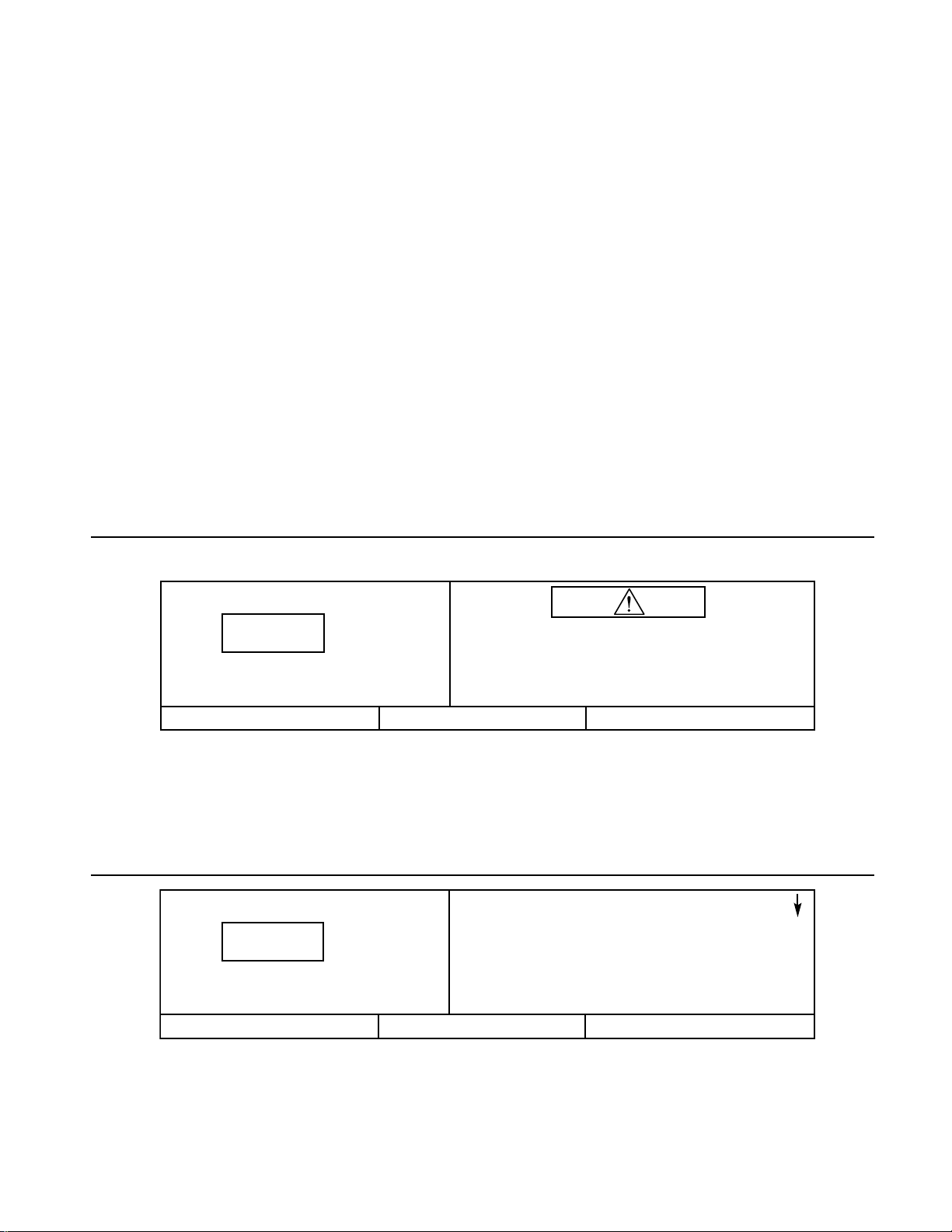
When an Alarm occurs, an exclamation mark will flash
on the display screen as shown above.The display
message will indicate what caused the Alarm.
Pressing the STATUS button will display the ALARM
STATUS screen with the ALARM button indicating an
Alarm still exists. Alarm Status is the list of machine
operating conditions that existed at the time of the
Alarm.
COMMUNICATION FAIL 1 (or 2 - 4) - This warning
will occur if the compressor is the lead unit while using
integral sequencing and is unable to communicate with
another compressor.
SERVICED REQUIRED -The Intellisys has 2 levels of
service.The service level can be set at the factory or
by an Ingersoll-Rand service representative. Either
service level will issue a “SERVICE REQUIRED”
warning at 150 hours.This warning is a reminder for
initial service and can be cleared by the operator.
Level 1 - If service level 1 (default) is selected, a
“SERVICE REQUIRED”warning will be issued every
2000 operating hours.This warning is to ser ve as a
reminder to have the unit serviced and can be cleared
by the operator.
Level 2 - If service level 2 is selected, service
warnings will be issued every 2000 operating hours
(default) or in 3, 6, 9, or 12 month intervals, as
selected at the factory or by an I-R service
representative.Service warnings at level 2 are issued
in 3 stages. First a “100 HOURS TO SERVICE” or 14
DAYS TO SERVICE” (depending on the ser vice
interval type) warning will be issued.This warning will
let the operator know that the time for service is
approaching and can be cleared by the operator.
Following that, 100 hours or 14 days later a “SERVICE
REQUIRED” warning will be issued. This warning can
be temporarily cleared by the operator, however it will
return 24 hours later if service has not been performed
by an I-R service representative. A new service period
will start when ser vice is performed. If another 100
hours or 14 days elapses and service has not been
performed, an “ALARM-SERVICE REQUIRED”
warning will be issued.This warning can only be
cleared by an I-R service representative.
SENSOR FAILURE 6APT - This warning will occur if
the separator delta-p sensor option is installed and
sensor 6APT is recognized as missing or broken.
27
3.11 WARNINGS (CONTINUED)
1 0 0
1 0 0
P S I
P S I
Page 30

28
The possible Alarm messages are as follows.
CHECK INLET CONTROL- This will occur if the
machine is unloaded and the inlet vacuum is less than
3 psig (.2 bar).
CHECK INLET CTRL SYS 1 (2) - This will occur if the
inlet butterfly valve fails to open or close properly. A 1
means the inlet valve failed to closer properly. A 2
means the inlet valve failed to open properly.
CHECK MOTOR ROTATION-This will occur if the
machine is started and the compressor has incorrect
rotation.
CONTROL POWER LOSS- This will occur if the
controller detects a loss of the 110 VAC or 120 VAC
control power.
EMERGENCY STOP- This will occur if the Emergency
Stop button is engaged.The button must be
disengaged before the alarm can be cleared.
FAN MOTOR OVERLOAD- This will occur if a fan
motor overload is sensed.
HIGH AIREND DISCH TEMP- This will occur if the
airend discharge temperature is greater than 228°F
(109°C).
LOW SUMP AIR PRESSURE- This will occur if the
machine is running fully loaded and the sump pressure
drops below 20 psig (1.4 bar).
LOW UNLOAD SUMP PRESS- This will occur if the
machine is running unloaded and the sump pressure
is less than 15 psig (1.0 bar) for 15 seconds.
MAIN MOTOR OVERLOAD- This will occur if a drive
motor overload is sensed.
CHECK SET POINTS- This will occur if the controller
has determined some of the data stored in memory
contains unacceptable values.When this occurs, the
sensors should be calibrated and all the set points
checked.It is normal for this alarm to occur after
changing controller software.
REMOTE START FAILURE- This will occur if the
Remote Start button is pressed after the machine is
running or if the Remote Start button remains closed.
REMOTE STOP FAILURE- This will occur if the
Remote Stop button remains open and either Start
button is pressed.
SENSOR FAILURE 1AVPT (or 3APT, 4APT,
5CPT,2CTT, 2ATT, 3CTT) - This will occur if a sensor
is recognized as missing or broken.This does not
apply to sensor 4ATT.
STARTER FAULT 1SL (2SL)- This will occur if the
starter contacts open while the machine is running. It
will also occur if the machine is given the stop
command and the starter contacts do not open. 1SL
refers to the auxiliary circuit on starter contact 1M. 2SL
refers to the auxiliary circuit on starter contacts 2M
and 1S.
STEPPER LIMIT SWITCH- This will occur if both limit
switches are activated at the same time.
INVALID CALIBRATION- This will occur during the
calibration process if the sensor reads greater than
20% of scale.
LOW COOLANT PRESSURE- This will occur if the
compressor is running and the following conditions are
met.The coolant must be less than 1 psi and either
the sump pressure is greater than 10 psi or the inlet
vacuum is less than 12 psi.
Page 31
4.0 SCHEDULED PREVENTATIVE MAINTENANCE
4.1 MAINTENANCE SCHEDULE
THE MAINTENANCE SCHEDULE SPECIFIES ALL RECOMMENDED MAINTENANCE REQUIRED TO KEEP THE
COMPRESSOR IN GOOD OPERATING CONDITION. SERVICE AT THE INTERVAL LISTED OR AFTER THAT
NUMBER OF RUNNING HOURS,WHICHEVER OCCURS FIRST.
4.2 MAINTENANCE RECORDS
It is very important that you, the owner, keep accurate
and detailed records of all maintenance work you, or the
Ingersoll-Rand Distributor or Air Center perform on your
compressor.This includes but is not limited to coolant
filter, separator, inlet air filter and so forth.This
information must be kept by you, the owner, should you
require warranty service work by your Ingersoll-Rand
Distributor or Air Center.Maintenance record sheets are
located at the back of this manual.
4.3 MAINTENANCE PROCEDURES
Before starting any maintenance, be certain the following
is heeded.
1. Read Safety Instructions.
2. Use correct tools.
3. Have recommended spares on hand.
SPECIAL NOTE:
Replace separator element when the separator
differential pressure ( ▲▲ P) reaches three times the
initial pressure drop or a maximum pressure
differential of 12 psi (.8 bar) at full load or if the
Intellisys warning CHANGE SEPARATOR ELEMENT is
displayed. See Section 3.9.
Running Time Interval (whichever comes first)
Action Part or Item Hours 1 Week 1 Mo. 3 Mo. 6 Mo. Yearly 2 Years
Inspect Coolant level Weekly x
Inspect Discharge temperature (air) Weekly x
Inspect Separator element differential Weekly x
Inspect Air filter Delta P (at full load) Weekly x
Inspect Oil filter Delta P Weekly x
Replace Coolant filter* 150 x (initial change only)
Check Temperature sensor 1000 x
Replace Food grade coolant (when used) 1000 x
Inspect Hoses 1200 x
Replace Coolant filter* 2000 x (subsequent changes)
Analysis Coolant 2000 See Section 4.15 x
Analysis Vibration 2000 See Section 4.15 x
Clean Separator scavenge screen and orifice 4000 x
Clean Cooler cores** 4000 x
Replace Air filter* 4000 x
Replace Separator element* *See special note.
Replace Ultra Coolant* 8000 x
Inspect Star ter contactors 8000 x
Service Drive motor lubrication See Section 4.10.
* In very clean operating environments and where inlet filter is changed at the above prescribed intervals.
In extremely dirty environments change coolant, filters, and separator elements more frequently.
** Clean cooler cores if discharge air temperature is excessive or if unit shutdown occurs on high air temperature.
29
Page 32
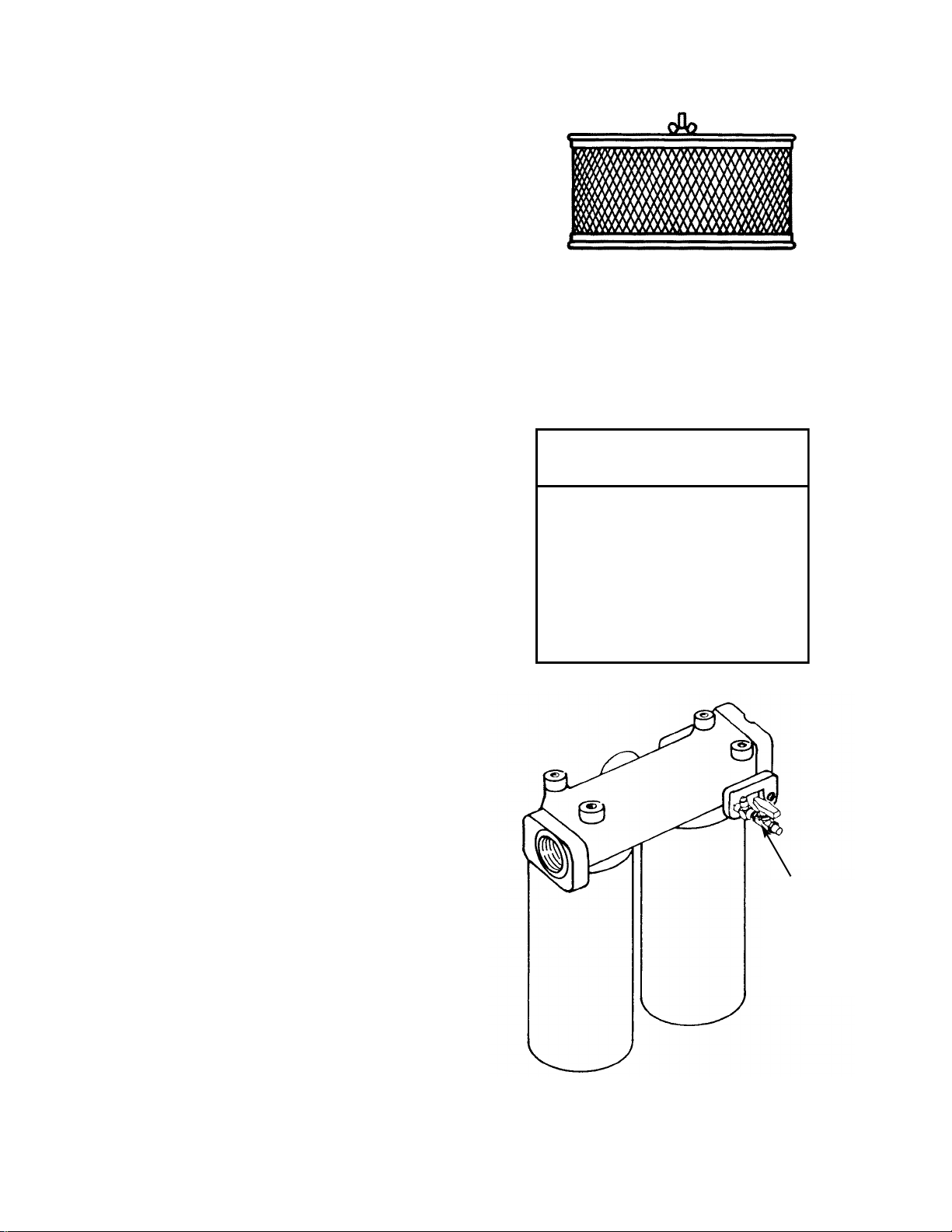
4.4 INLET AIR FILTER
To check condition of the inlet filter, run compressor in
the LOADED mode and observe “Inlet Filter”on the
CURRENT STATUS display screen. If the display says
“Inlet Filter OK”, then no maintenance is required. If “ ? ”
is flashing on the screen and the display says “CHANGE
INLET FILTER”, then the inlet filter should be changed.
To change inlet filter elements, loosen wing nut on top of
inlet filter housing. Lift cover up and away to expose
element/s.
Carefully remove the old element/s to prevent dirt from
entering the inlet valve.Discard old element/s.
Thoroughly clean the element housing and wipe all
surfaces.
Install new element/s and inspect to ensure that they
have seated properly.
Install top of inlet filter housing.
Inspect the rubber seal on the retainer wing nut and
replace seal if required.
Tighten wing nut.
Start machine and run in the load mode to verify filter
condition.
4.5 COOLANT FILTER
To check the condition of the coolant filter, the
compressor must be running. Observe “Injected
Temperature” on the CURRENT STATUS display screen.
If the temperature is less than 120°F (49°C), continue to
run the machine.When the temperature is greater than
120°F (49°C), observe “Coolant Filter” on the screen. If
the display says “Coolant Filter OK”, then the filter does
not need service. If “ ? ” is flashing on the screen and the
display says “CHANGE COOLANT FILTER”, then the
filter should be replaced.
Use a suitable device and loosen the old element.Use
drain pan to catch any leakage during removal.Discard
old element.
Wipe the sealing surface of the filter with a clean, lint-free
rag to prevent the entry of dirt into the system.
Remove the replacement element from its protective
package.Apply a small amount of clean lubricant on the
rubber seal and install the element.
Screw element/s on until the seal makes contact with the
head of the filter assembly. Tighten approximately
one-half turn additional.
Start unit and check for leaks.
INLET AIR FILTER
125-150 HP/90-110KW REQUIRES (1) ELEMENT
200 HP/132-160 KW REQUIRES (2) ELEMENTS
100 HP/75 KW-2S REQUIRES (1) ELEMENT
125-200 HP/110-160 KW - 2S REQUIRES (2)
ELEMENTS
COOLANT FILTER
100 HP/75 KW REQUIRES (1) ELEMENT
125-200 HP/90-160 KW REQUIRES (2) ELEMENTS
VALVE
FURNISHED
ONLY ON
UNITS
EQUIPPED
WITH
LUBRICANT
PUMP
30
CAUTION
Improper maintenance of
coolant filter can cause
compressor damage.
Change coolant filter after first
150 hours of operation and
every 2000 hours thereafter or
when coolant is changed.
Page 33
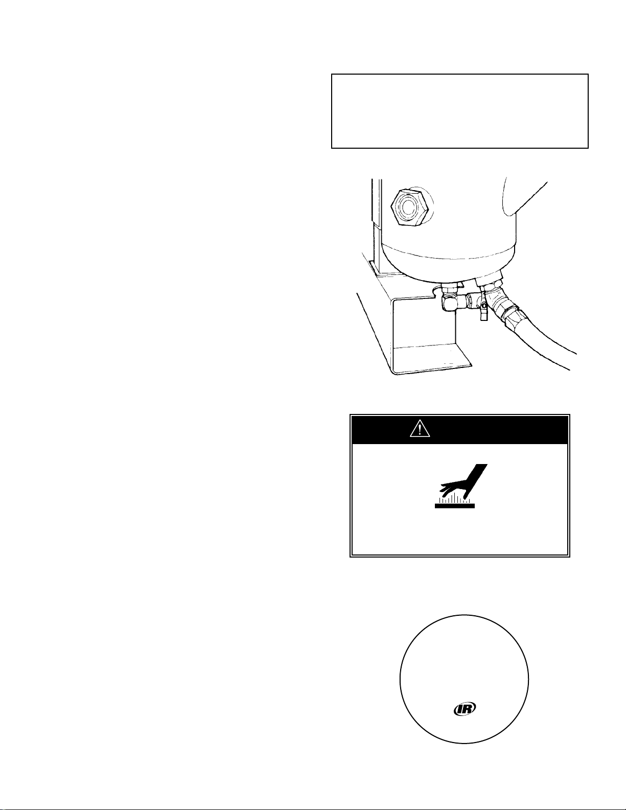
31
COOLANT DRAIN
4.6 COOLANT
■ SSR Ultra Coolant (Standard Factory Fill)
■ SSR H1-F Food Grade (Optional)
SSR Ultra Coolant is a polyglycol base coolant. Change
Ultra Coolant after every 8000 hours or every two years,
whichever comes first.
SSR Food Grade Coolant is a polyalphaolefin base
coolant. Change after every 1000 hours or every 6
months whichever comes first.Do not operate unit
beyond this 1000 hour lubricant change interval, as
lubricant degradation will occur.
Items Required
In addition to the tools normally found in any reasonably
equipped serviceman’s toolbox, the following items
should be available at the work site:
1) Suitable drain pan and container to hold lubricant
drained from unit.
2) A quantity of proper lubricant sufficient to refill the
compressor.
3) A minimum of one replacement coolant filter element
of the proper type for the unit to be worked on.
There is a coolant drain hose supplied with each
compressor.The drain hose is placed in the starter box
when shipped from the factory.
The coolant should be drained soon after the compressor
has been shut down.When the coolant is hot, drainage
will be more complete and any particles in suspension in
the coolant will be carried out with the coolant.
Hot coolant can cause severe injury. Use care when
draining separator tank.
To drain the unit, remove plug from drain valve located on
the bottom of the separator tank. Install supplied drain
hose and fitting assembly in end of drain valve and place
end of hose in a suitable pan. Open drain valve to start
drainage.After draining is complete, close valve, remove
hose and fitting assembly from valve, and store in a
suitable location for future use.Replace plug in end of
drain valve.
Do not store drain hose in starter box after it has
been used to drain the separator tank.
125-200 HP/90-160 KW - Single Stage.........23 gallons (87.4 liters)
100 HP/75 KW - 2 Stage ...............................22 gallons (83.3 liters)
125-200 HP/90-160 KW - 2 stage.................30 gallons (113.6 liters)
Coolant fill quantity
W ARNING
Hot coolant can cause severe injury.
Use care when near this area.
Filler Cap.
Use only
recommended coolant.
Read instruction book
before servicing.
39543921
Page 34
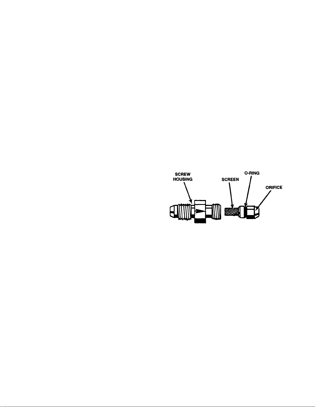
32
4.6 COOLANT (Continued)
After the unit is drained and a new coolant filter element
is installed, refill the system with fresh coolant. Bring the
receiver level of coolant up to the midpoint of the sight
glass. Replace the fill cap.Start the compressor and run
it for a short time.The correct coolant level is at the
midpoint of the sight glass with the unit running in the
‘UNLOADED” mode.
4.7 SEPARATOR TANK
SCAVENGE SCREEN/ORIFICE
TOOLS REQUIRED
■ Open end wrench
■ Pliers
PROCEDURE
The screen/orifice assemblies are similar in appearance
to a straight tubing connector and will be located
between two pieces of 1/4 inch O.D. scavenge line
tubing.
The main body is made from 1/2 inch hexagon shaped
steel and the diameter of the orifice and a direction-offlow arrow is stamped in flat areas of the hexagon.
A removable screen and orifice is located in the exit end
of the assembly (See Figure 4.7-1) and will require
cleaning as outlined in the Maintenance Schedule,
Section 4.1.
To remove the screen/orifice, disconnect the scavenge
line tubing from each end. Hold the center section firmly
and use a pair of pliers to gently grasp the exit end of the
assembly that seals against the scavenge line tubing.
Pull the end out of the center section while using care to
prevent damage to the screen or sealing surfaces.
Clean and inspect all parts prior to reinstallation.
When the assembly is installed, confirm the direction of
flow to be correct. Observe the small arrow stamped in
the center section and ensure the direction flow to be
from the separator tank to the airend.
FIGURE 4.7-1 SEPARATOR TANK SCAVENGE
SCREEN/ORIFICE
Page 35
W ARNING
125/200 HP
This machine contains high air pressure
which can cause severe injury or death
from hot oil or flying parts.
Always relieve pressure before removing caps,
plugs, covers or other parts.Blow down
pressurized air system. Close isolation valve.
See Operator’s Instruction Manual.
4.8 COOLANT SEPARATOR ELEMENT
To check condition of separator element, run
compressor in full load mode and at rated pressure and
observe “Separator Pressure Drop” on the CURRENT
STATUS display screen. If the display says “xxPSI”, then
no maintenance is required. If “ ? ” is flashing on the
screen and the display says “CHANGE SEPR
ELEMENT”, then the separator element should be
replaced.
Disconnect the scavenge tube at the airend.
Loosen the fitting that holds the scavenge tube into the
tank and withdraw the tube assembly.
Disconnect the piping from the tank cover.Tag the lines
if required.
Use a suitable wrench and remove the bolts that hold
the tank cover in position.Remove cover by lifting up
and away.
Carefully lift the separator element up and out of the
tank. Discard the faulty element.
Clean the gasket surface on both the tank and its cover.
Exercise care to prevent pieces of the old gasket from
falling down into the tank.
Check the tank to be absolutely certain that no foreign
objects such as rags or tools have been allowed to fall
into the tank. Install replacement element down into the
tank after checking the new element gaskets for
possible damage.Center the element up within the
tank.
Place the tank cover in its correct position and install
bolts.Tighten the bolts in a cross-patter n to prevent
over-tightening one side of the cover.An improperly
tightened cover will likely result in a leak.
Inspect tank scavenge screen and orifice.Clean if
necessary following instructions in Section 4.7.
Install scavenge tube down into the tank until the tube
just touches the separator element and then raise it 1/8
inch (3.2 mm). Tighten fittings.
Install the regulation lines in their original position.
Start unit, check for leaks, place in service.
100-200 HP/75-160 KW 5/8-11 UNC 150 ft-lb. (203 N-M)
Tank cover bolt torque values
RECOMMENDED BOLT TIGHTENING
CROSS PATTERN
33
Page 36
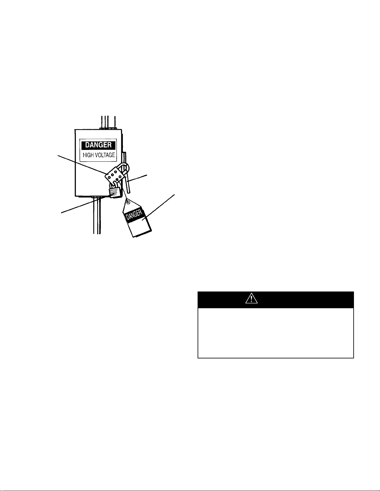
34
COOLANT COOLERS
Following are instructions for removal and internal
cleaning of coolant coolers.
Coolant Cooler
■ Remove panels and top cover.
■ Drain the coolant. See Section 4.6.
■ Remove side panels from coolant cooler box.
■ Disconnect piping from coolant cooler inlet and outlet
ports.
■ Plug cooler inlet and outlet ports to prevent possible
contamination.
■ Remove coolant cooler holding screws from sides of
coolant cooler and remove cooler through side of
cooler shroud.
Coolant Cooler Cleaning
■ It is recommended the cooler be taken to a
professional cooler service shop for flushing with an
appropriate environmentally safe cleaning agent.
■ Reassemble in reverse order.
■ Make sure fan guards are replaced.
■ Refill the compressor with coolant. If contamination is
suspected, replace with new coolant.
■ Replace fill plug.
■ Run compressor for ten minutes.Check for possible
leaks. Check coolant level.
■ Replace enclosure panels.
4.9 COOLER CORES: CLEANING
Ensure the compressor is isolated from the
compressed air system by closing the isolation valve
and venting pressure from the drip leg.
Ensure the main power disconnect switch is locked
open and tagged. (See Figure 4.9-1).
TOOLS REQUIRED
■ Screwdriver
■ Wrench set
■ Air hose equipped with approved O.S.H.A. nozzle.
On units sold outside the U.S.A. consult
local codes.
PROCEDURE
Visually check the outside of the cooler cores to be
certain that a complete outside cleaning of the cooler is
required. Frequently, dirt, dust or other foreign material,
may only need to be removed with an air hose to remedy
the problem.
When the cooler is covered with a combination of
oil, grease or other heavy substances that may
affect the unit’s cooling, then it is recommended
that the cooler cores be thoroughly cleaned on the
outside.
If it is determined that the compressor operating
temperature is higher than normal due to the internal
passages of the cooler cores being restricted with
deposits or foreign material, then the cooler should be
removed for internal cleaning.
Strong cleaners can harm
aluminum cooler parts. Follow cleaner
manufacturer’s instructions for use.
Wear appropriate safety equipment.
CAUTION
FIGURE 4.9-1 MAIN DISCONNECT
LOCKED AND TAGGED
HASP
LEVER
TAG
KEY LOCK
Page 37

35
AFTERCOOLER
Following are instructions for the removal and internal
cleaning of aftercoolers.
Aftercooler
■ Disconnect hose from aftercooler inlet flange.
■ Disconnect tube from aftercooler outlet flange.
■ Remove aftercooler holding screws from aftercooler
support and remove cooler.
Aftercooler Cleaning
■ It is recommended the cooler be taken to a
professional cooler service shop for flushing with an
appropriate environmentally safe cleaning agent.
■ Reassemble in reverse order.
■ Replace enclosure panels.
Page 38
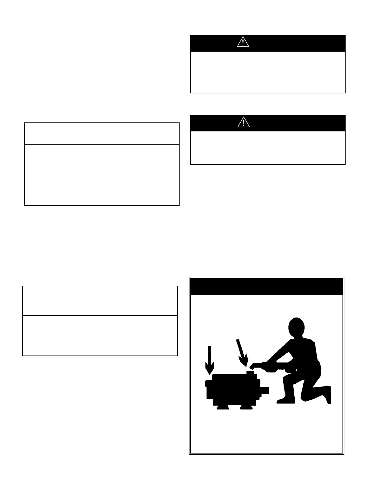
36
Overgreasing can be a cause of bearing and
motor failure. Make sure dirt and contaminants
are not introduced when adding grease.
CAUTION
4.10 MOTOR LUBRICATION
The induction-type squirrel cage motors have antifriction
ball or roller bearings front and rear.At periodic intervals
they require relubrication.
Relubrication Interval - 60 Hz
(or 9 months, whichever comes first)
1000 hours ......................................all TEFC drive motors
2000 hours .........all ODP drive motors and all fan motors
When regreasing, stop motor.Disconnect power; lock out
and tag. Remove outlet plugs (or spring-loaded grease
relief plugs if present).The outlet plug may not be
accessible on the fan end of some TEFC motors.
Grease should be added when the motor
is stopped and power disconnected.
CAUTION
Lubricant Amount
Motor Frame Size in
3
cc oz. grams
182-215 .5 8 .4 11
254-286 1.0 16 .8 23
324-365 1.5 25 1.2 34
404-449 2.5 40 2.0 57
5000 Frame Series 1.0 16 .8 23
Relubrication amount
Procedure for relubrication
NO TICE
Motors must be greased periodically.
See Operator’s Manual for procedure.
Relubrication Interval - 50 Hz
(or 9 months, whichever comes first)
2000 hours..................M90 - 160 KW TEFC drive motors
4000 hours ...................................M75 TEFC drive motors
Improper lubrication can be a cause of motor bearing
failure.The quantity of grease added should be carefully
controlled.The smaller motors must be greased with a
lesser amount of grease than larger motors.
Lubricant Amount
Motor Frame Size in
3
cc oz. grams
M75-160 As indicated on motor
nameplate
Relubrication amount
Page 39
37
4.10 MOTOR LUBRICATION (Continued)
Grease relief along shaft can occur, precluding necessity
of removing this plug if inaccessible.The inlet grease gun
fittings and outlet plugs (or spring-loaded reliefs) are
located at each end of the motor housing.The dr ive end
reliefs protrude out the circumference of the lower portion
of the end bell near a flange bolt.The dr ive end outlet
plugs are located just behind the flange in the air intake
area at about the 5 or 6 o’clock position.
1) Free drain hole of any hard grease (use piece of wire
if necessary).
2) Use a hand lever type grease gun.Determine in
advance the quantity of grease delivered with each
stroke of the lever.A graduated cylinder showing
cubic centimeters (cc) may be used, or a 35mm film
canister can give a close approximation for 2 cubic
inches when filled.
3) Add the recommended volume of the recommended
lubricant. Do not expect grease to appear at the
outlet, but if it does, discontinue greasing at
once.
4) Run motor for about 30 minutes before replacing outlet plugs or reliefs. BE SURE TO SHUT MOTOR
DOWN, DISCONNECT POWER, LOCK OUT AND
TAG,AND REPLACE THESE DRAIN FITTINGS TO
PRECLUDE LOSS OF NEW GREASE AND
ENTRANCE OF CONTAMINANTS!
Recommended Motor Grease
60 Hz motors require:
Mobilith SHC 220 (39218193)
Use the grease as indicated on a special grease
information nameplate on the motor. Use of alter native
greases can result in shortened motor life due to
incompatibility of greases. If there is not a grease
nameplate on the motor use:
Chevron Black Pearl #2 (39204292)
(Preferred)
Chevron SRI 2 (39161641)
50 Hz motors require
Esso Unirex N3 (92844729)
MOTOR BEARING MAINTENANCE
(STORED UNITS)
To ensure that complete contact is maintained between
the motor bearings and the bearing grease on units to be
placed in storage for extended intervals, the following
motor maintenance procedure should be adhered to:
1) Prior to placing a unit in storage, rotate the motor
several revolutions by hand in the proper direction of
rotation.
2) Thereafter, rotate the motor as described in Step 1 at
three month intervals until such time as the unit is
placed in service.
3) If the storage time is to exceed a total of nine (9)
months duration, the compressor must be ordered
with long term storage option.
!
WARNING
Hazardous voltage. Can cause
severe injury or death.
Disconnect power before servicing.
Lockout/Tagout machine.
Page 40
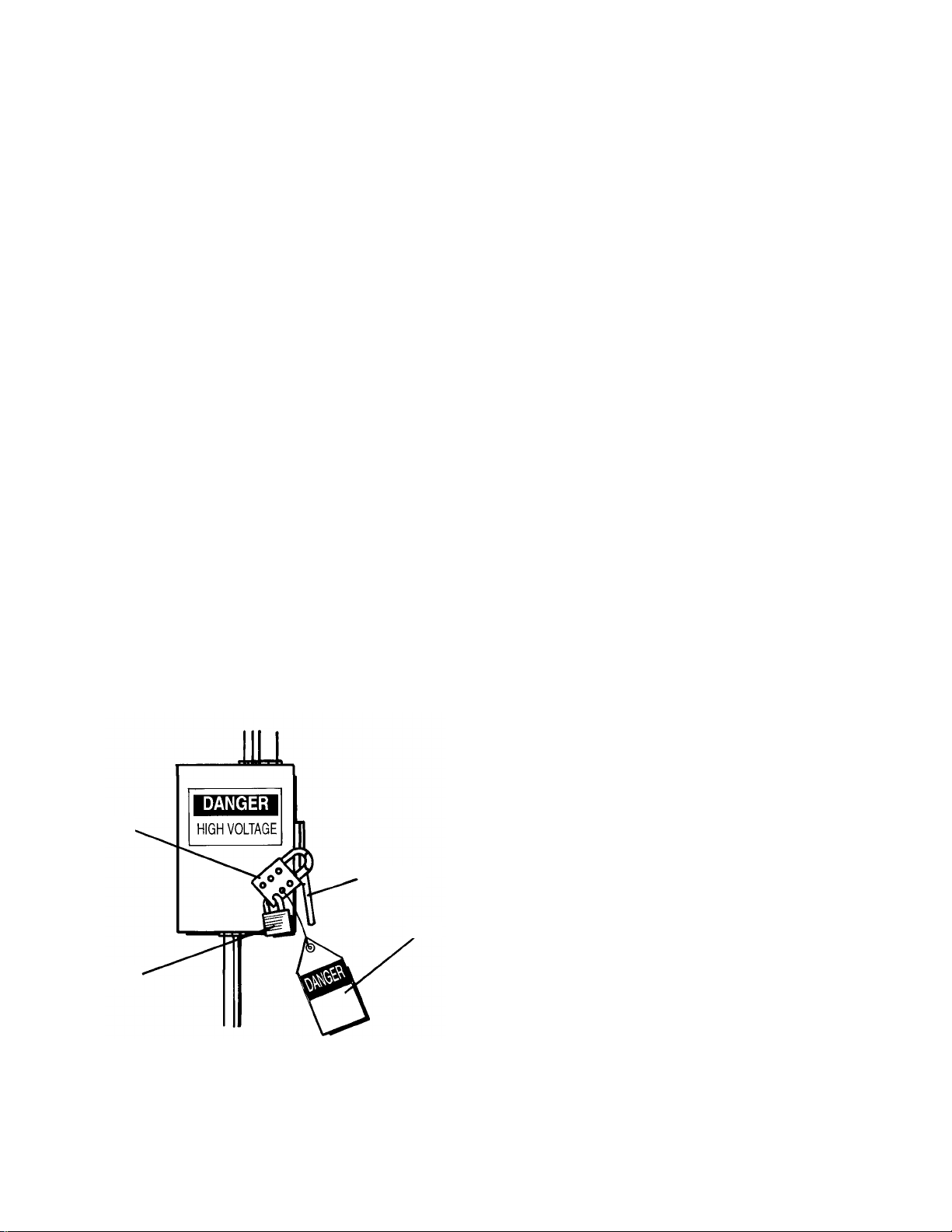
38
4.11 LONG TERM STORAGE
GENERAL
The factory, upon special request, prepares compressor
units for long term storage.In such cases, a special
bulletin is supplied for storage and start-up procedures.
The bulletin provides special procedures for rotation and
lubrication of compressors during storage.
Before actual start-up of the compressor, the unit must
be drained of coolant containing vapor space inhibitors.
Procedure for long term storage start-up is covered in the
special bulletin APDD 339.
4.12 COOLANT/LUBRICANT CHANGEOUT Ingersoll-Rand does not recommend changeout of coolant/lubricants, however, if a coolant/lubricant change cannot be avoided, procedure APDD 106E-87 should be obtained from your Ingersoll-Rand representative.
4.13 INTELLISYS REMOVAL
Ensure the compressor is isolated from the
compressed air system by closing the isolation
valve and venting pressure from the drip leg.
Ensure the main power disconnect switch is locked
open and tagged (See Figure 4.13-1).
FIGURE 4.13-1 MAIN DISCONNECT
LOCKED AND TAGGED
HASP
LEVER
TAG
KEY LOCK
Follow these precautions to minimize damage from
static electricity. Static can cause severe damage to
microcircuits.
1) Make the least possible movement to avoid building up static electr icity from your clothing or tools.
2) Discharge potential static electr icity by touching
(grounding) yourself to the starter box.
3) Handle circuit boards only by their edges.
4) Do not place the controller or power supply
assembly on any metal surface.
5) Leave the replacement parts in their protective
bags until ready for installation.
Tools:
Screwdriver Size #1, flathead
3/8 inch hex driver
Before removing any components, open the starter box
door and check all wiring for tightness.A loose wire or
bad connection may be the cause of problems.
This section gives guidelines for removing/replacing the
Intellisys Controller assembly and the Intellisys Power
Supply assembly. The controller is mounted in the
starter box door, and the power supply is mounted on
the upper right corner of the star ter backpanel on the
inside-rear of the starter box.
Controller Removal:
1) Open the starter box door.
2) Remove each plug-in connector, labeled P1-P10,
from the sides of the controller. If any of the
cables are not labeled, label them with the
appropriate plug designator, P1-P10. These
must be plugged into the correct sockets in
the replacement controller.
3) Remove and save the Option Module if one is
plugged into P9.This must be installed in the
replacement controller.Note that it is keyed to
plug into P9 only one way.
4) Remove the six holding screws from the controller on the inside of the starter box door.
5) Remove the controller through the front of the
door, being careful to save the gasket that is
between the controller and the door.
Page 41
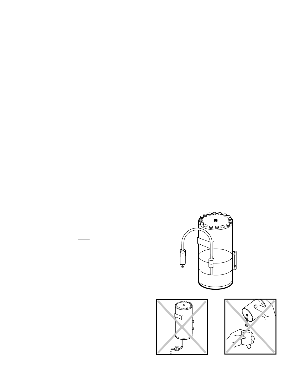
39
Power Supply Removal:
1) Open the starter box door.
2) Remove each plug-in connector, labeled J1 J4, from the circuit board. If any of the cables
are not labeled, label them with the appropriate plug designator, J1-J4.These must
be plugged into the correct sockets in the
replacement power supply.
3) Remove the four screws holding the power
supply to the starter plate, save them for
mounting the replacement board, and remove
the power supply.
4.14 COOLANT HOSES
The flexible hoses that carry coolant to and from the oil
cooler may become brittle with age and will require
replacement. Have your local Ingersoll-Rand distributor
check them every 2 years.
Ensure the compressor is isolated from the
compressed air system by closing the isolation valve
and venting pressure from the drip leg.
Ensure the main power disconnect switch is locked
open and tagged.
REMOVAL
Remove enclosure panels.
Drain coolant into a clean container.Cover the container
to prevent contamination.If the coolant is contaminated,
a new charge of coolant must be used.
Hold fitting securely while removing hose.
INSTALLATION
Install the new hoses and reassemble the package by
reversing the disassembly procedure. Start the
compressor and check for leaks.
4.15 FLUID AND VIBRATION MONITORING
Ingersoll-Rand recommends incorporating predictive
maintenance, specifically the use of coolant and vibration
analysis, into all Preventative Maintenance programs.
Predictive Maintenance is designed to increase system
reliability and prevent costly downtime.Through the use
of sophisticated diagnostic tools, including fluid, vibration,
and optional air analysis, IRA Certified Service
Technicians can identify and correct potential problems
BEFORE they can cause expensive unscheduled
downtime.
How does predictive analysis work? By establishing an
initial baseline for normal operation, and then regularly
monitoring fluid and vibration conditions, any sudden
deviation or significant increase from this baseline can be
identified and investigated to pinpoint the cause.More
quickly diagnosing potential problems can directly save
money by preventing costly failures and reducing or
eliminating downtime.In addition, regular condition
monitoring also helps to maximize the time between
expensive preventative maintenance intervals, such as
component rebuilds and coolant changes.
4.16 COOLANT SAMPLING PROCEDURE
Bring unit up to operating temperature. Draw sample,
using pump kit, from separator tank port. DO NOT draw
sample from drain port or oil filter. Use new hose on
pump for each sample, failure to do this can give false
readings.
100%
50%
OIL FILTER
Page 42

40
COOLING FAN MOTOR
In a standard compressor, the cooling fan motor is wired
at the factory. It is a three-phase motor, protected by a
suitable circuit breaker and overload relay. The fan motor
is energized at the same time the compressor drive
motor is energized.The fan motor overload is wired in
series with the compressor drive motor overload. If an
overload occurs in the fan motor circuit, both the fan
motor and compressor drive motor will stop.
AFTERCOOLER
The discharge air aftercooling system consists of a heat
exchanger (located at the cooling air entrance of the
machine), a condensate separator, and an automatic
drain trap.
By cooling the discharge air, much of the water vapor
naturally contained in the air is condensed and
eliminated from the downstream plant-piping and
equipment.
5.3 COOLANT SYSTEM
Coolant is forced by pressure from the receiver/separator
sump to the inlet port of the coolant cooler and the
bypass port of the thermostatic control valve.
The thermostatic control valve controls the quantity of
coolant necessary to provide a suitable compressor
injection temperature.When the compressor starts cold,
part of the coolant will bypass the cooler.As the system
temperature rises above the valve setting, the coolant will
be directed to the cooler.Dur ing per iods of operation in
higher ambient temperatures, all the coolant flow will be
directed through the cooler.
The compressor injection minimum temperature is
controlled to preclude the possibility of water vapor
condensing in the receiver. By injecting coolant at a
sufficiently high temperature, temperature of the
discharge air and lubricant mixture will be kept above the
dew point.
The controlled temperature coolant passes through a
filter to the airend under constant pressure.
5.0 SYSTEMS
5.1 GENERAL SYSTEM INFORMATION
The SSR compressor is an electric motor driven, single
stage, screw compressor—complete with accessories
piped, wired and baseplate mounted. It is a totally
self-contained air compressor package.
A standard compressor is composed of the following:
■ Inlet air filtration
■ Compressor and motor assembly
■ Pressurized coolant system with cooler
■ Separation system
■ Capacity control system with stepper motor inlet
■ Motor starting control system
■ Instrumentation
■ Safety provisions
■ Aftercooler
■ Moisture separator and drain trap.
Optional accessories can provide for such things as
automatic starting and stopping, remote star ting or
stopping, and sequencer.
The motor, airend, separator tank, and piping are
mounted on independent supports.The supports are
isolated from the base by rubber isolation mounts.
Flexible hoses are utilized on the separator tank coolant
out and air discharge to isolate the motor/airend/tank.
5.2 AIR COOLED COMPRESSORS
DESIGN TEMPERA TURES
The standard compressor is designed for operation in an
ambient range of 35°F to 115°F (1.7°C to 46°C).When
conditions other than the design levels described are
encountered, we recommend you contact your nearest
Ingersoll-Rand representative for additional information.
The standard maximum temperature 115°F (46°C) is
applicable up to an elevation of 3300 ft (1000 m) above
sea level.Above this altitude, significant reductions in
ambient temperature are required if a standard drive
motor is to be used.
COOLANT COOLER
The cooler is an integral assembly of core, fan and
fan-motor, all mounted in the end section of the
compressor enclosure.The cooling air flows in through
the left end of the enclosure, through the vertically
mounted cooler core, and discharges upward through the
right end of the enclosure.
Page 43

5.4 COMPRESSED AIR SYSTEM
The air system is composed of:
1) Inlet air filter
2) Inlet valve/stepper motor
3) Rotors
4) Coolant/air separator
5) Minimum pressure/check valve
6) Aftercooler
7) Moisture separator/drain trap
Air enters the compressor, passing through the inlet air
filter and butterfly inlet valve.
Compression in the screw-type air compressor is created
by the meshing of two helical rotors (male and female) on
parallel shafts, enclosed in a heavy-duty cast iron
housing, with air inlet and outlet ports located on
opposite ends.The grooves of the female rotor mesh
with, and are driven by, the male rotor.Tapered roller
bearings at the discharge end prevent axial movement of
the rotors.
The air-coolant mixture discharges from the compressor
thru a discharge check valve into the separation system.
This system, self-contained in the separator tank,
removes all but a few PPM of the coolant from the
discharge air.The coolant is returned to the system and
the air passes to the aftercooler.The aftercooling system
consists of a heat exchanger, a condensate separator,
and a drain trap.By cooling the discharge air, much of
the water vapor naturally contained in the air is
condensed and eliminated from the downstream
plant-piping and equipment.
During unloaded operation, the butterfly inlet valve
closes, via stepper motor, and the blowdown solenoid
valve opens, expelling any compressed air back to the
compressor inlet.
5.5 COOLANT/AIR SEPARATION SYSTEM
The coolant/air separation system is composed of a
separator with specially designed internals, a two-stage
coalescing-type separator-element, and provision for
return of the separated fluid back to the compressor.
Internal baffles maintain the circumferential flow of
remaining coolant droplets and air.In an almost
continuous change of direction of flow, more and more
droplets are removed from the air by inertial action and
then returned to the sump.
The air stream, now essentially a very fine mist, is
directed to the separator element.
The separator element is constructed with two
concentric, cylindrical sections of closely packed fibers,
each held in steel mesh. It is flange-mounted at the
separator-outlet-cover.
The air stream enters the separator element radially
and the mist coalesces to form droplets.The droplets
collected on the outer first stage fall to the separator
sump.Those collected on the inner second stage
collect near the outlet of the element, and are drawn
back to the compressor inlet through a filter-screen and
orifice fitting installed in the separator scavenge line.
The air stream, now essentially free of coolant, flows
from the separator to the aftercooler, then to the
condensate separator, and on to the plant air system.
5.6 ELECTRICAL SYSTEM
The electrical system of each SSR compressor is built
around the microprocessor-based Intellisys controller.
The standard electrical/electronic components,
enclosed in a readily accessible enclosure include:
1) IntelIisys controller
2) Compressor motor starter, with auxiliary contacts
and overload relays
3) Cooling fan motor overload relays and circuit
breaker or fuses
4) Intellisys Power Supply Board
5) Control transformer and fuses
Options, such as power outage restart can be enabled
by installing plug-in (option) modules in the Intellisys
controller.
OPERATION
The coolant and air discharging from the compressor
flow into the separator through a tangential discharge
outlet.This outlet directs the mixture along the inner
circumference of the separator, allowing the coolant
stream to collect and drop to the separator sump.
41
Page 44

5.6 ELECTRICAL SYSTEM (Continued)
ST AR-DEL T A TYPE ST AR TER
By use of the Star-Delta type starter, the compressor
motor can be started and accelerated using a greatly
reduced “inrush” electric current. The starter is completely
automatic and controlled by the Intellisys controller. Refer
to the Electrical Schematic 8.1 in Section 8.0.
5.7 STEPPER MOTOR INLET CONTROL
The inlet valve is opened and closed by a stepper motor
mounted on the inlet valve.The Intellisys controller
regulates the stepper motor to precisely position the inlet
valve based upon the demand of the plant air system
(See Section 5.8).
The stepper motor is maintenance free. Bearings are
lubricated at the factory and sealed for life.
No adjustment of the stepper motor/inlet valve system is
required.
5.8 CAPACITY CONTROL
The SSR compressor is supplied, as standard
equipment, with three operator selectable capacity
control systems, each designed for different plant air
requirements:
— MOD/ACS (Modulation/Automatic
Control Selector)
— On-Off Line
— Modulation Only
The desired control is selected at the Intellisys control
panel (See Section 3.0).
AUTOMATIC UNLOADED START
The compressor will always start in the unload mode.
When unloaded, the inlet valve is nearly closed, the
blowdown solenoid valve is open (tank vented), and the
compressor is operating at minimum power.The Intellisys
will open the inlet valve slightly to maintain the proper
sump pressure to ensure positive coolant flow and
smooth, quiet operation.When the injected coolant
temperature is less than 120°F (49°C), a separator
(sump) pressure of 45-50 psig (3.1 - 3.4 bar) will be
maintained.When the injected coolant temperature is
above 120°F (49°C), a receiver pressure of 24-33 psig
(1.7 - 2.3 bar) will be maintained.The minimum pressure
check valve will prevent any backflow of air from the plant
air system during unloaded operation.
ON-OFF LINE CONTROL
For those plants which have a widely varying air demand,
on-off line control will deliver air at full capacity
(compressor maximum efficiency condition) or will
operate at zero capacity (compressor minimum power
condition).The compressor is controlled by the Intellisys,
responding to changes in plant air pressure.The
Intellisys/stepper motor opens the inlet valve and closes
the blowdown valve (3SV) whenever plant air pressure
drops below the on-line pressure set point.The
compressor will then operate to deliver full capacity air to
the plant system. If the plant air system pressure rises to
the off-line set point of the Intellisys, the inlet valve closes
and the blowdown solenoid valve opens the separator
vent line, allowing separator pressure to drop.The
compressor will continue to run with minimum power
draw.
MODULATION/ACS CONTROL
For those plants which have relatively high, constant
air-demand relative to the compressor capacity, the
recommended control mode is modulation.
The modulation control system retains the features of
on-off line control, but provides for throttling of the inlet
flow up to the modulation off line air pressure set point.
The throttling position of the inlet valve is controlled by
the Intellisys, allowing the stepper motor to “trim”the inlet
valve position as dictated by the line pressure.
The modulating pressure range is 10 psig (.7 bar).
Modulation begins when the line pressure reaches the
maximum modulation pressure setting minus 10 psig (.7
bar) and continues as/if the line pressure rises.
Modulation becomes stable when the compressor output
equals the plant air demand.When the modulation is at
the maximum modulation pressure setting the maximum
capacity reduction will be down to approximately 60
percent of the compressor rated capacity.If the air
demand has decreased to a level below the 60 percent
modulated output, the line pressure will increase slightly
to actuate the Intellisys, unloading the compressor and
venting the separator.
42
Page 45

5.8 CAPACITY CONTROL (Continued)
MODULATION/ACS CONTROL (Continued)
The automatic control selector (ACS) is designed to
continuously monitor the plant air demand and select
either the on-off line, or the modulate control mode whichever is most desirable at any time during an
operating day.
It allows the compressor to operate in its most efficient
mode without attendance, thereby reducing power costs
to a minimum.
When the compressor operates in the on-off line control
mode, the length of time the compressor remains in the
“off line” condition is an indication of the plant air
demand. Intellisys controller is sensing and awaiting a
sufficient line pressure decrease before signaling a shift
to the on line mode. If the “off line” time period is
relatively short, thereby indicating a high demand for air,
it is preferable to shift the control system to upper range
modulation.
The Intellisys does this, and does it automatically if the
compressor unloads 3 times within a 3 minute time
period.
If later, the plant demand decreases, and even under
modulate control the line pressure reaches the setting of
the Intellisys controller and the control shifts to the “off
line” mode, the time in this mode will still be monitored. A
long “off line” time period indicates a low plant air
demand, indicating the desirability of operating in the
on-off line mode.
The Intellisys then does this, and does it automatically if
the compressor operates unloaded for more than 3
minutes.
MODULATION ONLY
If MODULATION ONLY is turned on in the set point
routine, the unit will shift to Modulation control mode
immediately when the unit is running. The 3 cycles within
3 minutes time period required for ACS to change to
Modulation mode is bypassed.The unit will stay in
Modulation mode until the UNLOAD button is pressed or
the Mode of Operation set point is changed.
43
5.9 AUTOMATIC START/STOP CONTROL
Many plant air systems have widely varying air demands
or large air storage capacity which allows for automatic
standby air capacity control.
During periods of low air demand, if the line pressure
rises to the upper set point, the Intellisys begins to time
out. If the line pressure remains above the lower set point
for as long as the set time, the compressor will stop. At
the same time the display will indicate the compressor
has shut down automatically and will restart
automatically. An automatic restart will occur when the
line pressure drops to the lower set point.
The upper and lower set points and shutdown delay time
are set on the Intellisys control panel.There is a 10
second delay after shutdown during which the
compressor will not restart even if line air pressure drops
below the lower set point.This is to allow the motor to
come to a complete stop and the Intellisys controller to
collect current data of operating condition. If line air
pressure is below the lower set point at the end of 10
seconds, the unit will start unless the load delay timer is
set greater than 10 seconds.
Auto Restart Delay
This is the number of seconds the line pressure must
remain below the online set point before the compressor
will start if it was stopped due to an auto start/stop
situation.This timer will not delay an auto restar t if the
time is set to 0.
Automatic Start/Stop Operation
When in operation, the compressor must meet two
specific timing intervals before the Intellisys controller will
stop the unit in an Automatic Start/Stop situation.
For this discussion, the timers will be called timer “A”and
timer “B”.
FIRST
Timer “A” prevents the compressor from automatically
starting more than 6 times an hour by requiring the unit
to run at least 10 minutes after each automatic start.
This 10 minute run period can be loaded, unloaded or a
combination of the two and allows dissipation of heat
generated within the motor windings at start.
Page 46

44
SECOND
After the compressor has started and reached the off-line
setting and has unloaded, timer “B” requires the unit to
run unloaded for a period of time that the operator can
adjust between 2 and 60 minutes.
The setting of timer “B” is part of the options setpoint
routine and the timer cancels any accumulated time if the
compressor reloads before the timer cycle has finished.
An important point... This unloaded run time may, or may
not, be included in the mandatory 10 minute run time
used to cool the motor windings.
When the compressor has completed the settings of both
timer “A” and timer “B”, the Intellisys controller stops the
compressor and displays “STOPPED IN AUTO
RESTART.”
Pressure sensor 4APT continues to monitor the package
discharge pressure and sends information to the
controller which automatically restarts the compressor
when the pressure falls to the on-line setting.
An advantage to this method of automatic start/stop
control is allowing the compressor to stop much sooner
in certain situations and timer settings, thereby reducing
power costs.
Some Examples of Operation
EXAMPLE 1
The operator selects an unloaded run time of 2 minutes
in the OPTION routine and starts the compressor.The
unit runs loaded for 8 minutes, unloads and then runs
unloaded for two more minutes.
The total running time is 10 minutes which satisfies timer
“A” plus the unit ran two minutes unloaded which also
satisfies timer “B,” therefore, the unit stops automatically.
This example shows how timer “B” can sometimes be
included within the timer “A” interval.Think of the two
timers as running parallel.
EXAMPLE 2
The operator selects an unloaded run time of 3 minutes
in the OPTION routine and starts the compressor.The
unit runs loaded for 10 minutes and then unloads.
At this point, timer “A” has been satisfied but timer “B” still
wants the compressor to run unloaded 3 more minutes
before allowing an automatic stop.
The total run time for this example will be 13 minutes.
Remember....If the unit reloads before timer “B” finishes
the 3 minute setting, the partial time is canceled and
timer “B” must restart the 3 minute cycle when the
compressor unloads again.
Page 47
45
EXAMPLE 3
The operator selects an unloaded run time of 10 minutes
in the OPTION routine and starts the compressor.The
unit runs loaded 12 minutes and then unloads.
After 12 minutes of running, the 10 minute mandatory
run-time for timer “A”has been met but the compressor
must continue to run unloaded an additional 10 minutes
to satisfy timer “B”.
After 10 minutes of unloaded run time, the compressor is
stopped automatically and the total run time was 22
minutes.
5.10 REMOTE START/STOP
The remote start/stop option allows the operator to
control the compressor from a remote mounted start/stop
station.
Two different switches can be wired to the controller for
remote start/stop. (Refer to Electrical Schematic 8.1 for
wiring locations).The switches are customer supplied
and must be of momentary type.The stop switch
contacts are normally closed and the start switch
contacts are normally open.
When starting the compressor from the remote location,
the Start button must be held depressed for
approximately 2 seconds to activate the remote start
function and then released within a maximum of 7
seconds or a Remote Star t Failure alarm will occur.
!
WARNING
This machine is remote
start and stop equipped.
May start or stop at
anytime.
Can cause severe injury or
death.
Disconnect power before
servicing.
Lock and tag out.
See Operators / Instruction
Manual.
Page 48

46
6.0 TROUBLESHOO TING CHART
TROUBLE
Compressor fails to start.
Compressor shuts down.
NOTE:If a shutdown
occurs, press the Status
button once to activate
the display table.Using
the adjacent up and
down arrows, the values
displayed will be those
immediately preceding
shutdown. Use these
values when
troubleshooting a
problem.
CAUSE &/OR DISPLAY
110/120V control voltage not available,
CONTROL POWER LOSS
STARTER FAULT
EMERGENCY STOP
MAIN (OR FAN) MOTOR OVERLOAD
SENSOR FAILURE XXXX
CHECK INLET CTRL SYS.
Intellisys 24 VAC control voltage not
available
Display panel and power on light does
not illuminate.
HIGH AIREND DISCH TEMP.
LOW UNLOAD SUMP PRESS.
CHECK INLET CTRL SYS.
SENSOR FAILURE XXXX
CHECK MOTOR ROTATION
MAIN MOTOR OVERLOAD
FAN MOTOR OVERLOAD
STARTER FAULT
CHECK SET POINTS
CONTROL POWER LOSS
STEPPER LIMIT SWITCH
REMOTE STOP FAILURE
REMOTE START FAILURE
EMERGENCY STOP
LOW SUMP AIR PRESS
CHECK INLET CONTROL
WHA T TO DO
■ Check fuses. Check transformer and wiring connections.
■ Inspect contactors.
■ Rotate emergency stop button to disengage, and press reset button
twice.
■ Manually reset main or fan motor overload relay, and press reset
button twice.
■ Check for defective sensor, bad sensor connection, or broken
sensor wires.
■ Call factory representative.
■ Check fuses.
■ Check wiring. Verify 24 VAC is within voltage tolerance (± 15%).
■ Ensure that installation area has adequate ventilation.
■ Ensure that cooling fan is operating. If not, reset circuit breaker
inside starter box.
■ Check coolant level. Add if required.
■ Cooler cores dirty. Clean coolers.
■ Check for air leak from tank or blowdown piping.
■ Check for slipping or broken stepper motor coupling.
■ Call factory representative.
■ Check for defective sensor, bad sensor connection, or broken
sensor wires.
■ Interchange any two line connections (L1, L2, L3) at the starter.
■ Check for loose wires.
■ Check supply voltage.
■ Check heater setting.
■ Check for loose wires.
■ Check supply voltage.
■ Check heater setting.
■ Check for dirty cooler cores.
■ Inspect starter connectors.
■ Check for loose wires.
■ Reset to clear.
■ Calibrate sensors.
■ Check all set points.
■ Check fuses. Check transformer and wiring connections.
■ Call factory representative.
■ Check Remote Stop Switch and wiring.
■ Check Remote Start Switch and wir ing.
■ Disengage emergency stop button.
■ Press reset button twice.
■ See LOW UNLOAD SUMP PRESS
■ Check for air leaks at inlet valve.
■ Check for slipping or broken stepper motor coupling.
Page 49

6.0 TROUBLESHOO TING CHART (Continued)
TROUBLE
Low system air pressure
High coolant
consumption/coolant in
air system
Water in air system
Excessive noise level
Excessive vibration
Pressure relief valve
opens
CAUSE &/OR DISPLAY
Compressor running in
UNLOAD Mode.
Controller off-line set point too low.
Dirty air filter element.
Air leak.
Moisture separator trap drain
stuck open.
Inlet valve not fully open.
System demand exceeds compressor
delivery.
Excessive coolant level.
Plugged separator element.
Separator element leak.
Plugged separator scavenge
screen/orifice.
Compressor operating at low pressure
(75 psig [5.2 bar] or below).
Coolant system leak.
Defective moisture
separator/drain trap
Trap drain or drain piping plugged.
Aftercooler core dirty.
Enclosure panels not in place.
No aftercooler on unit.
Drain line/drip leg incorrectly installed.
No refrigerated or desiccant dryer
in air system.
Compressor defective.(Bearing or gear
failure or rotor contact.)
Enclosure panels not in place.
Loose component mounting.
Loose components.
Motor or compressor
bearing failure.
External sources.
Compressor operating over pressure.
Defective valve.
WHA T TO DO
■ Press LOAD button.
■ Press STOP button.
Set off-line set point at a higher value.
■ Check filter condition. Replace as required.
■ Check air system piping.
■ Inspect and repair.
■ Inspect and repair. Check control system operation.
■ Install larger or an additional compressor.
■ Check level, lower if necessary by draining.
■ Check separator pressure drop.
■ Check separator pressure drop. If low, replace element.
■ Remove and inspect screen/orifice. Clean if required.
■ Operate at rated pressure. Reduce system load.
■ Inspect and repair leaks.
■ Inspect and clean if required.
Replace separator/trap if defective.
■ Inspect and clean.
■ Inspect and clean.
■ Install enclosure panels.
■ Install aftercooler.
■ Slope drain line away from trap.Install drip leg.
■ Contact local Ingersoll-Rand distributor.
■ Contact authorized distributor immediately.
Do not operate unit.
■ Install enclosure panels.
■ Inspect and tighten.
■ Inspect and tighten.
■ Contact authorized distributor immediately.
Do not operate unit.
■ Inspect area for other equipment.
■ Adjust Intellisys set points.
■ Replace valve.
47
Page 50

48
7.0 OTIONS
7.1 POWER OUTAGE RESTART OPTION
For customers that have interruptions in their incoming
power supply to the compressor and must maintain an
uninterrupted supply of compressed air, the Power
Outage Restart Option allows an Intellisyscompressor to
restart automatically 10-120 seconds (adjustable) after
incoming power is restored.
The Power Outage Restart Option is tur ned on by
plugging in the required option module and enabling it
thru the OPTION’S set point routine.The restart time
delay, which is adjustable from 10-600 seconds, can also
be adjusted while in the option’s set routine on the
Intellisys controller.Any time power is restored to the
compressor after a power interruption, a horn located on
the side of the starter box will sound during the restart
time delay (10-600 seconds), after which the compressor
will automatically start. After starting, the compressor will
return to the mode of operation that the compressor was
in prior to the power interruption.
This option may be factory installed or a field installation
kit is available.
7.2 SEQUENCER
The sequencer option is turned on by enabling it through
the OPTIONS set point routine. Enabling this
option will allow the compressor to be controlled by an
external device, such as an ISC or sequencer, using
the communications port (P7) on the Intellisys.
7.3 LOW AMBIENT
The lowambient option is turned on by enabling it through
the OPTIONS set point routine. Also temperature sensor,
3CTT, is added to the compressor and connected at P6-7
& 8 on the Intellisys.The options set point, minimum
cooler out temperature, is set to the minimum temperature
at which the unit can load.When this option is enabled,
the compressor, after being started, will not load until the
Intellisys reads a temperature from 3CTT at or higher
than the value of the minimum cooler out temperature set
point. If this option is enabled without installing 3CTT,
a SENSOR FAILURE 3CTT alarm will occur.
7.4 SEPARATOR DELTA-P SOLENOID
The separator delta-p solenoid option is turned on by
enabling it through the OPTIONS set point routine.
When this option is enabled, the Intellisys will measure
the pressure drop across the separator element by
first reading the wet side sump pressure.Next the
Intellisys will momentarily energize solenoid that will
switch the dry side sump pressure to the sump pressure
sensor (3APT).The Intellisys will then read the dry
side sump pressure and subtract it from the wet side
sump pressure to measure the pressure drop across the
separator element. Do not enable this option if the
separator delta-p solenoid is not installed.This will
result in an incorrect measurement of the pressure
drop across the separator element.
7.5 SEPARATOR DELTA-P SENSOR
The separator delta-p sensor option is turned on by
enabling it through the OPTIONS set point routine.
When this option is enabled, the Intellisys will measure
the pressure drop across the separator element by
subtracting the dry side sump pressure (6APT) from the
wet side sump pressure (3APT). Do not enable this
option if the separator delta-p sensor is not installed.
This will result in an incorrect measurement of the
pressure drop across the separator element and a
6APT sensor failure warning.
7.6 HIGH DUST FILTER
The high dust filter option is turned on by enabling it
through the OPTIONS set point routine. If this option
is enabled, the Intellisys; will change its measurement of
the inlet filter.Do not enable this option unless a high
dust filter is installed.
7.7 LEAD/LAG CYCLE LENGTH
The lead/lag cycle length option allows the Intellisys to
automatically switch the online and offline pressure
settings to the lead or lag values after a programmed
number of hours.This option is enabled by selecting a
number of hours greater than 0 in the OPTIONS set point
routine.
7.8 SCHEDULEDSTART/STOP
The scheduled start/stop option allows the customer to
automatically start and stop the compressor once each
day, based on the real time clock. This is an installed
option and is enabled by selecting a scheduled start and
scheduled stop time. Setting the scheduled start and
scheduled stop times to the same value will disable this
option.
Page 51

7.9 REMOTE LOAD/UNLOAD
The remote load/unload option gives the operator the
ability to control the loading and unloading of the
compressor.This option is enabled when two switches
are wired to the Intellisys to perform this function.
The firstswitch is the master/local input (P3, 25 & 26)
and the second switch is the load/unload input (P3,
27 & 28). If the master/local switch is closed, the
Intellisys will read the load/unload switch for loading
and unloading the compressor.If the load/unload switch
is closed, the Intellisys will load the compressor.
If the load/unload switch is open, the Intellisys will
unload the compressor.If the master/local switch is
open, the Intellisys will ignore the load/unload switch
and operate the compressor normally.
7.10 MODBUS
The Modbus option uses the Modbus protocol and
modbus address set points in the OPTIONS menu.This
is used by the Ingersoll-Rand service organization.
7.11 INTEGRAL SEQUENCING
Integral sequencing allows one compressor, the lead, to
sequence up to 3 other compressors.The compressors
are daisy chained together using port P8 on the Intellisys.
Each compressor has a unique address and the lead
compressor will sequence the other units in numerical
order based on that address.
The lead compressor will be the first to load and the last
to unload. It is also the only compressor that can
modulate. If the lead compressor’s mode of operation is
Mod/ACS or Modulation Only, it will modulate when it is
loaded. Once loaded, if pressure falls to its online set
point, the lead compressor will transmit a load command
to the next compressor in sequence.The lead compressor
will then wait for a period of time for the line pressure to
rise.This time per iod is determined by the load delay time
set point. At the end of this time period, if line pressure is
not rising, the lead compressor will transmit a load
command to the next compressor in sequence.This will
be repeated until the line pressure starts to rise.
When line pressure rises to the lead compressor’s offline
set point, it will transmit an unload command to the last
loaded compressor in the sequence.The lead compressor
will do this every 10 seconds until the line pressure starts
to fall.
After a certain amount of time or at a cer tain time, the
lead compressor can change the sequence by transferring
the lead to the next compressor in the sequence.If the set
point, Lead Change - Hours, is set to a value greater than
0, the unit will operate as the lead compressor for that
number of hours before transferring the lead. If Lead
Change - Hours is set to 0, the set points Lead Change Day and Lead Change - Time will be used to determine
when the lead will be transferred.The Lead Change - Day
set point will contain the day of the week the lead will be
transferred.The time of the day will be contained in the
Lead Change - Time set point.The lead will be transferred
when the real time clock matches these 2 set points.
To connect the compressors for integral sequencing put
the 4 position connector into port P8. One connector, I-R
part number 39186101, will be needed for each
compressor.The total length of cable for an integral
sequencing system is not to exceed 1000 feet.For the
cable, use I-R part number 39204508 or equivalent.This
is a 4 wire, twisted pair cable.Use one pair for pins 1 and
2 and the other pair for pins 3 and 4.The connection on
port P8 is a one to one connection. The wire on pin 1 on
the first compressor will connect to pin 1 on the second
compressor and so on.This is tr ue for all 4 wires.
49
Page 52
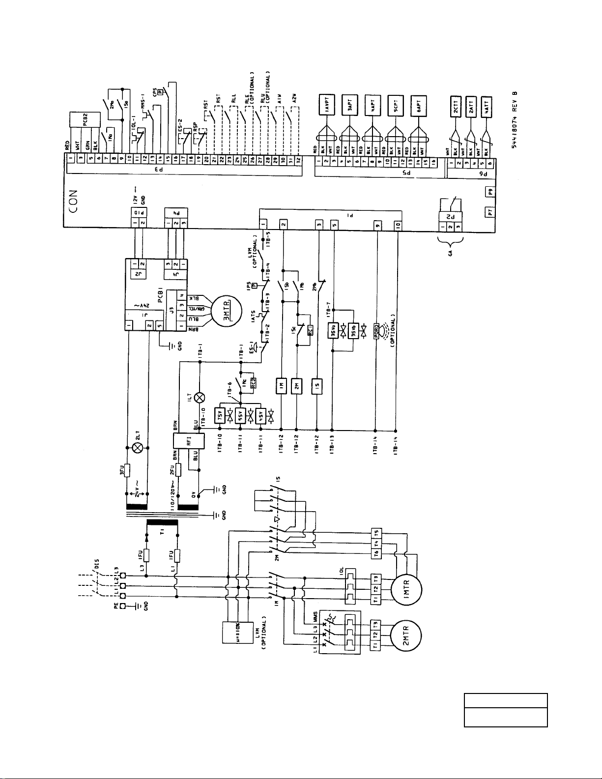
50
54418074
REV B
8.0 REFERENCE DRAWINGS
8.1 ELECTRICAL SCHEMATIC
STAR DELTA
Page 53
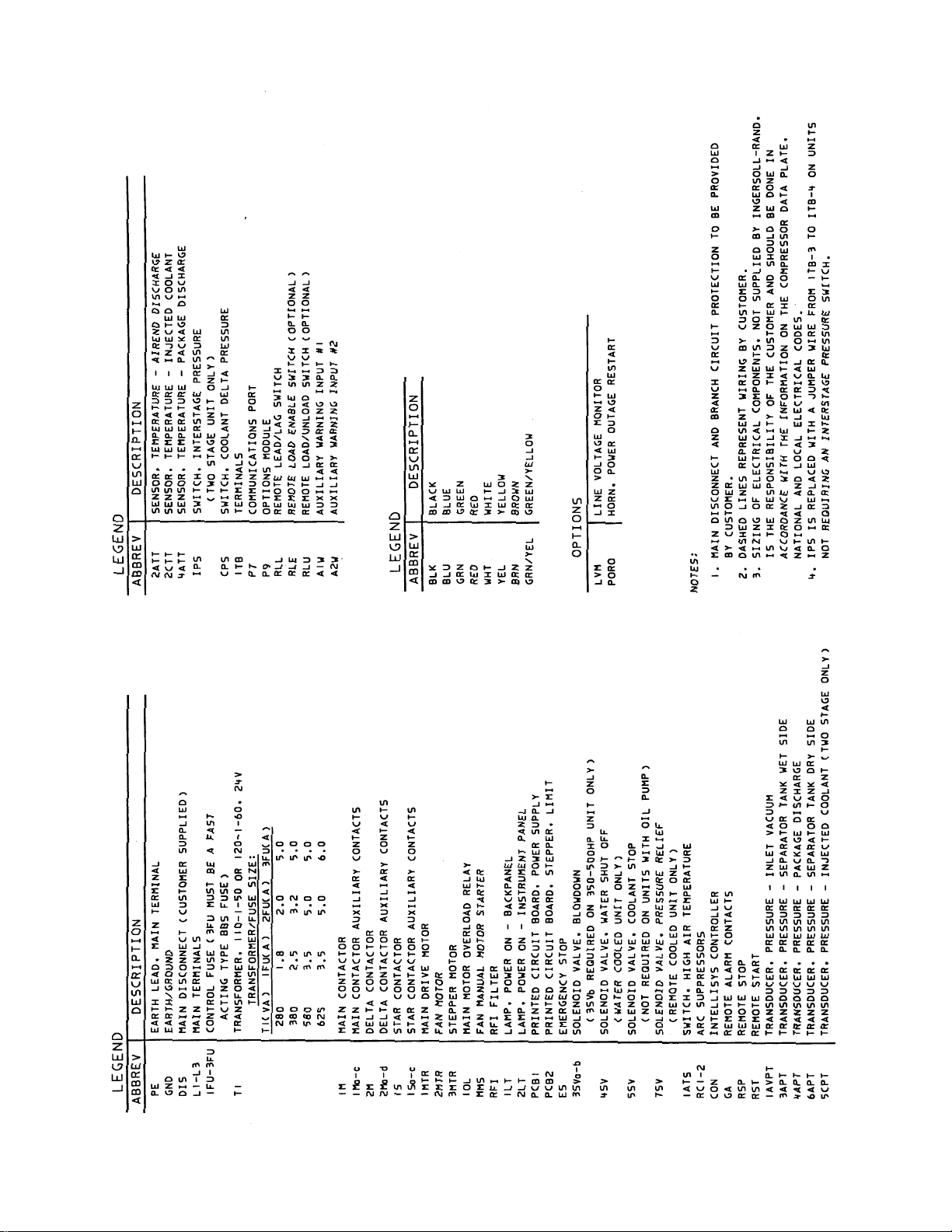
51
Page 54
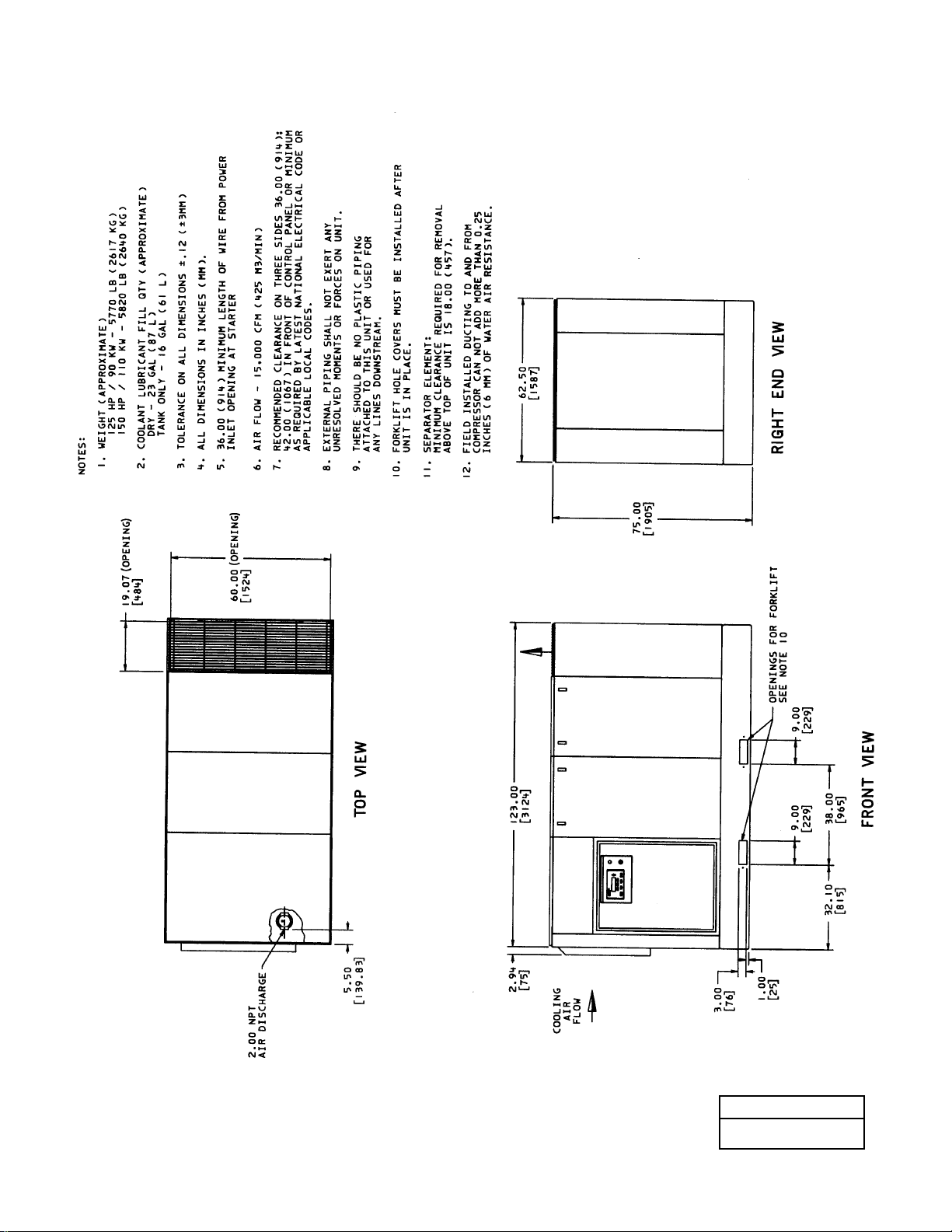
52
54622865
REV B
8.2 FOUNDATION PLAN
125-150 HP/90-110KW AIRCOOLED
SINGLE STAGE
(CONTINUED)
Page 55
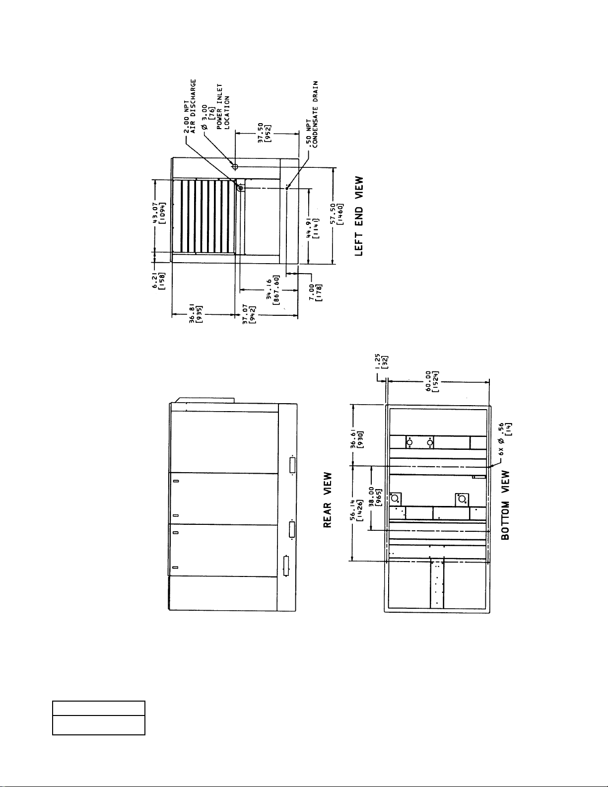
53
54622865
REV B
8.2 FOUNDATION PLAN
125-150 HP/90-110 KW AIRCOOLED
SINGLE STAGE
Page 56
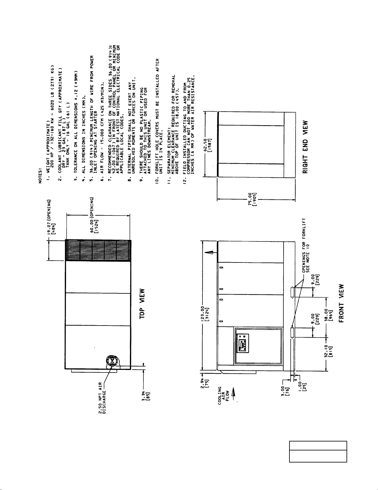
8.3 FOUNDATION PLAN
200 HP/132-160 KW AIRCOOLED
SINGLE STAGE
(CONTINUED)
54622931
REV B
54
Page 57
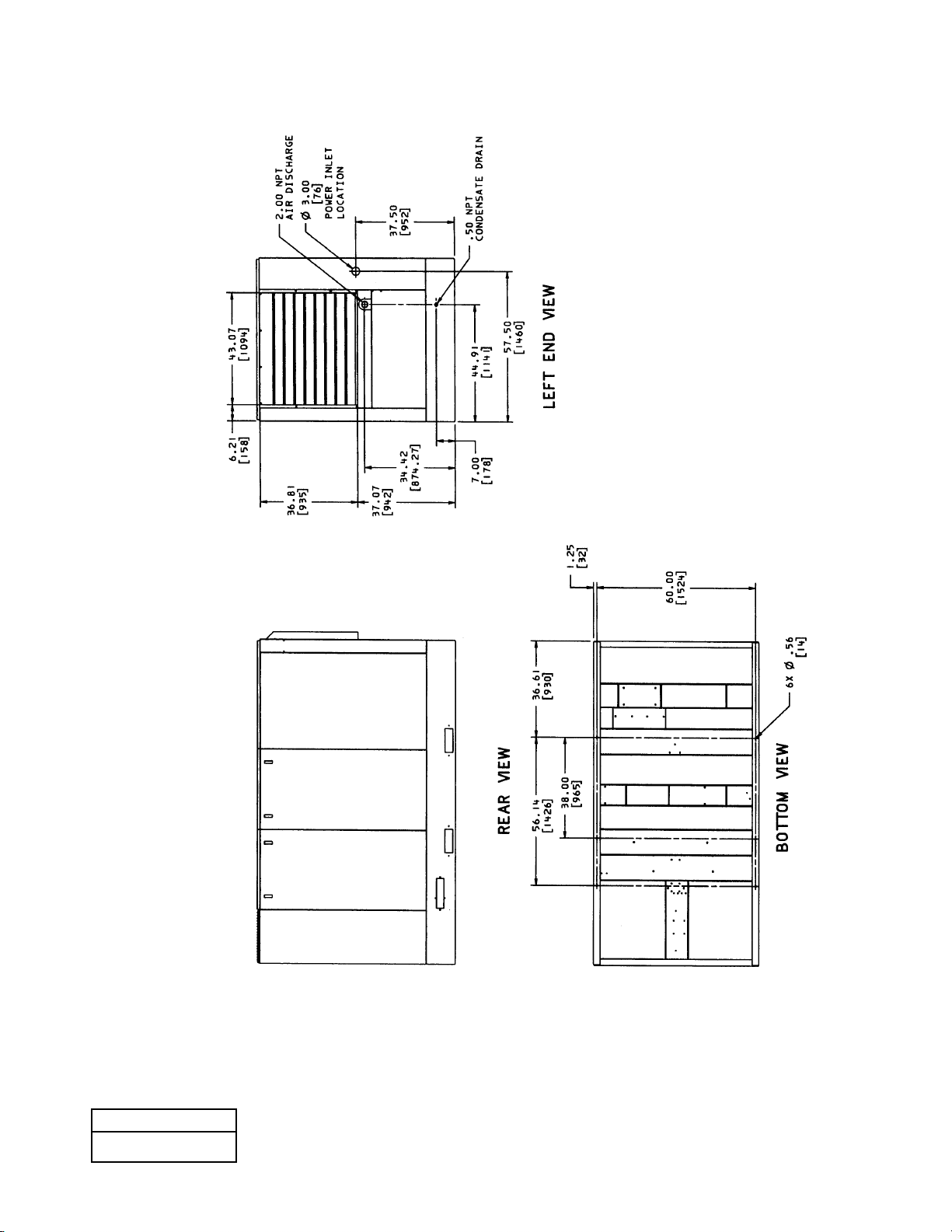
8.3 FOUNDATION PLAN
200 HP/132-160 KW AIRCOOLED
SINGLE STAGE
54622931
REV B
55
Page 58
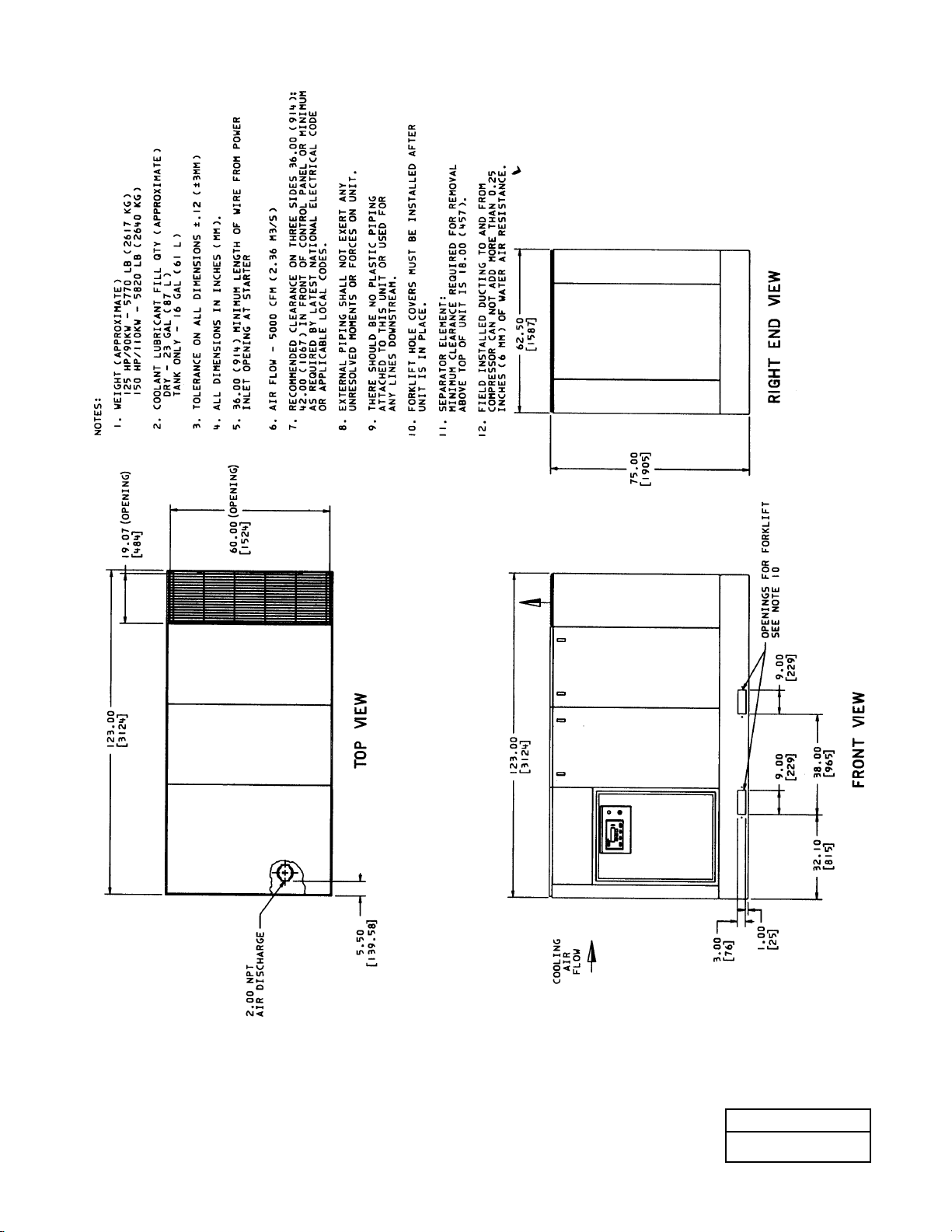
56
8.4 FOUNDATION PLAN
125-150 HP/90-110 KW WATERCOOLED
SINGLE STAGE
(CONTINUED)
39925300
REV C
Page 59
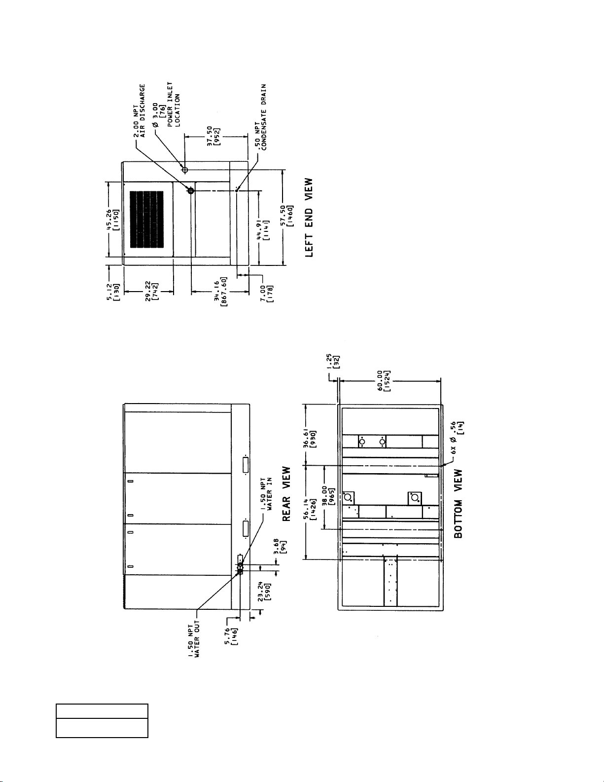
57
8.4 FOUNDATION PLAN
125-150 HP/90-110 KW WATERCOOLED
SINGLE STAGE
39925300
REV C
Page 60
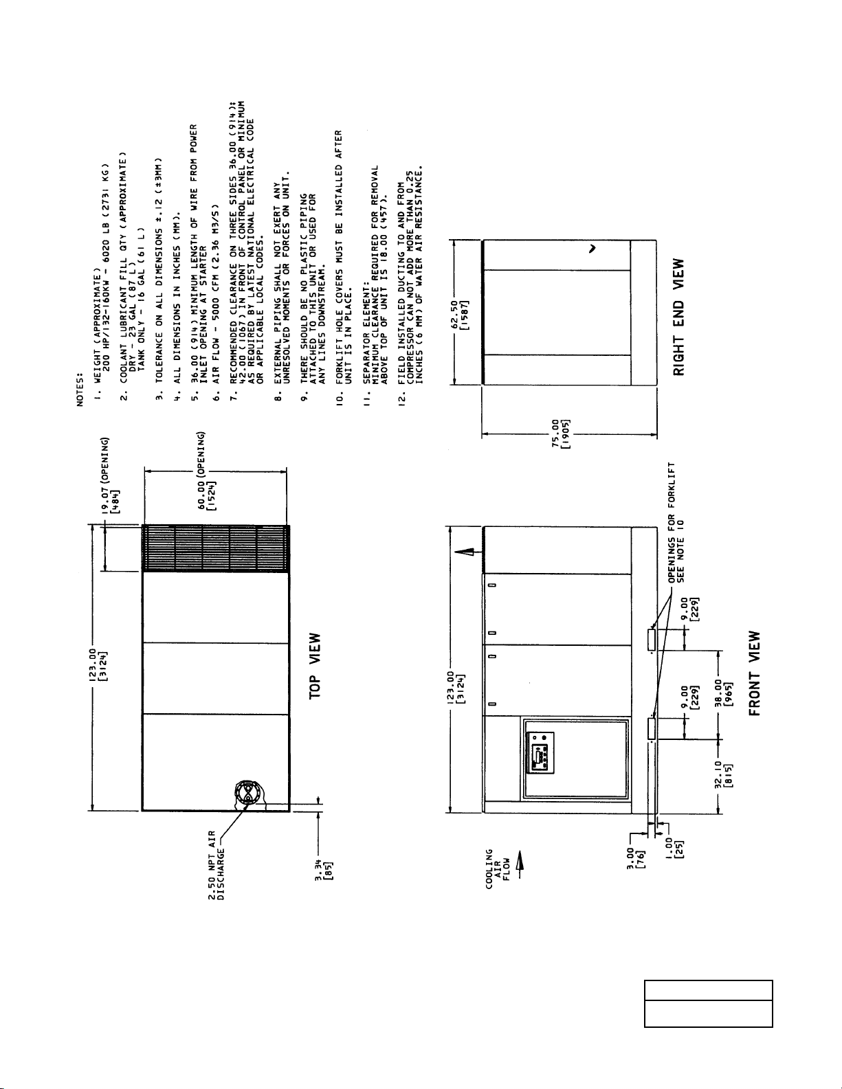
58
8.5 FOUNDATION PLAN
200 HP/132-160 KW WATERCOOLED
SINGLE STAGE
(CONTINUED)
39926191
REV C
Page 61
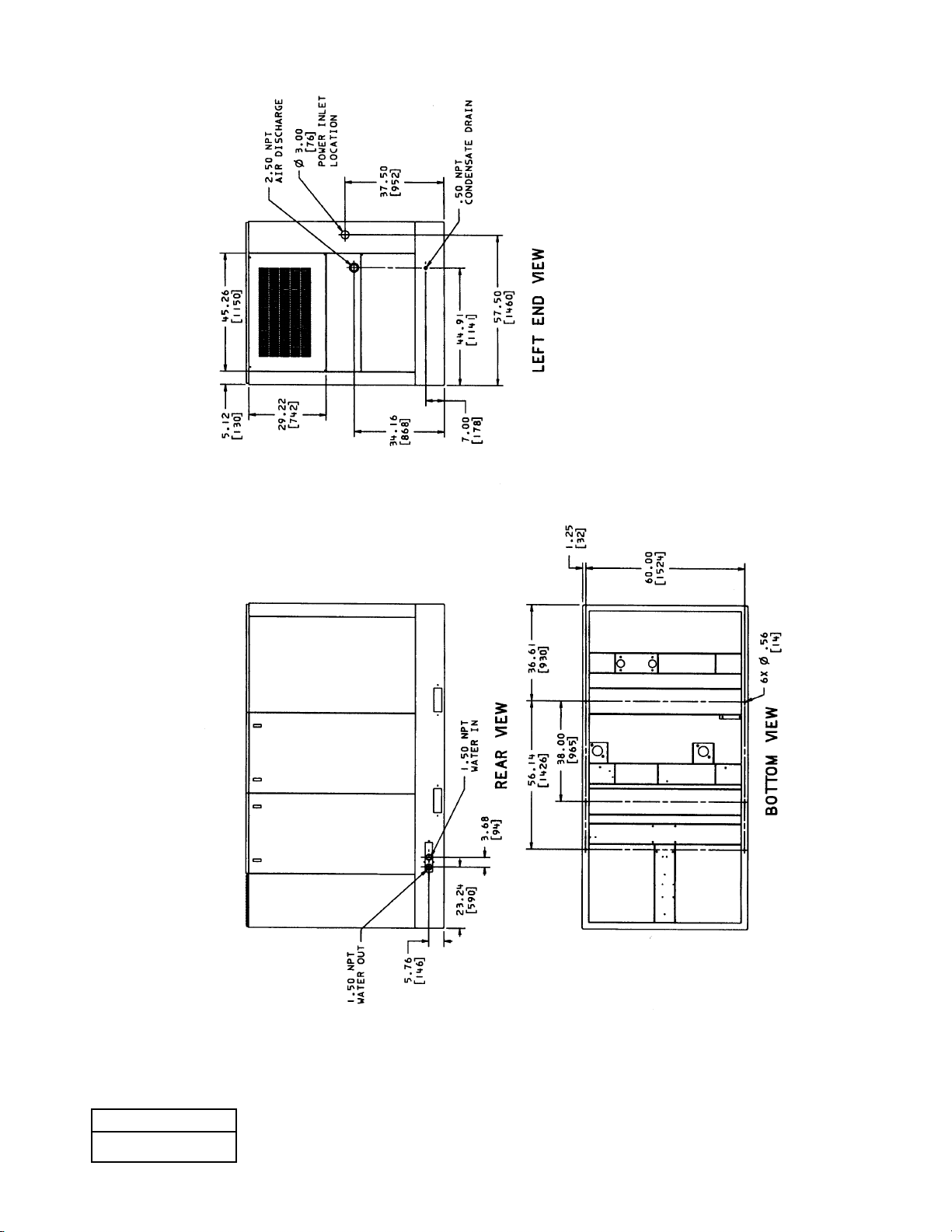
59
8.5 FOUNDATION PLAN
200 HP/132-160 KW WATERCOOLED
SINGLE STAGE
39926191
REV C
Page 62
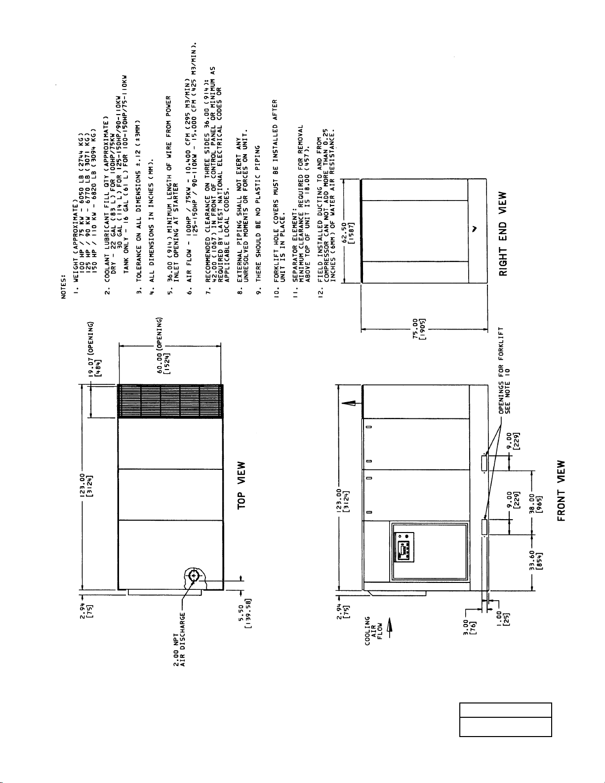
60
8.6 FOUNDATION PLAN - AIRCOOLED (CONTINUED)
100-150 HP/75-110 KW - TWO STAGE
54622980
REV B
Page 63
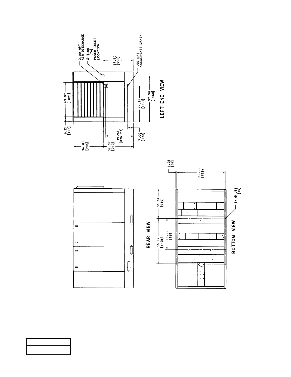
61
54622980
REV B
8.6 FOUNDATION PLAN - AIRCOOLED
100-150 HP/75-110 KW - TWO STAGE
Page 64
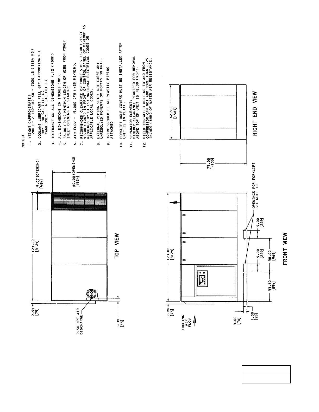
62
8.7 FOUNDATION PLAN - AIRCOOLED (CONTINUED)
200 HP/132-160 KW - TWO STAGE
54623053
REV B
Page 65
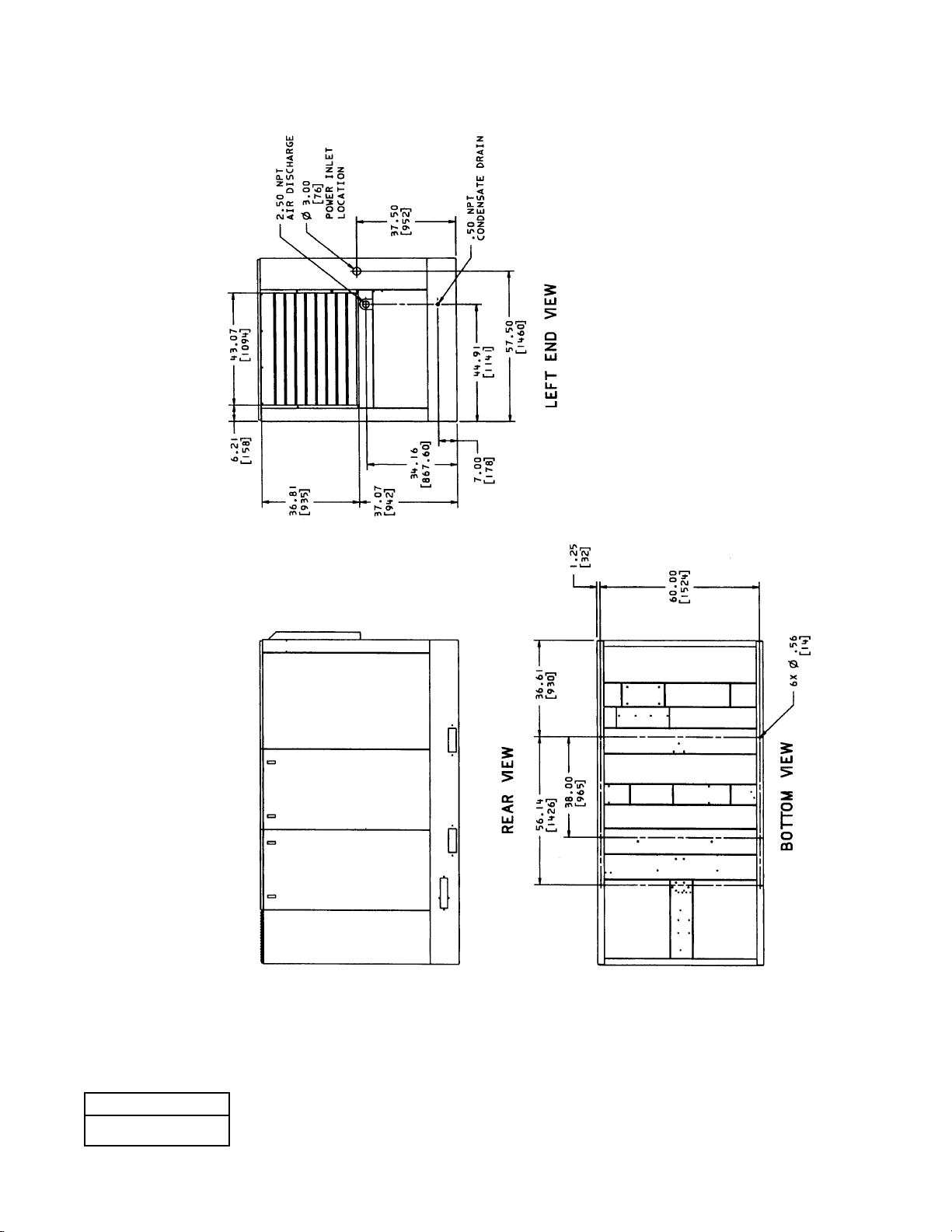
63
54623053
REV B
8.7 FOUNDATION PLAN - AIRCOOLED
200 HP/132-160 KW - TWO STAGE
Page 66
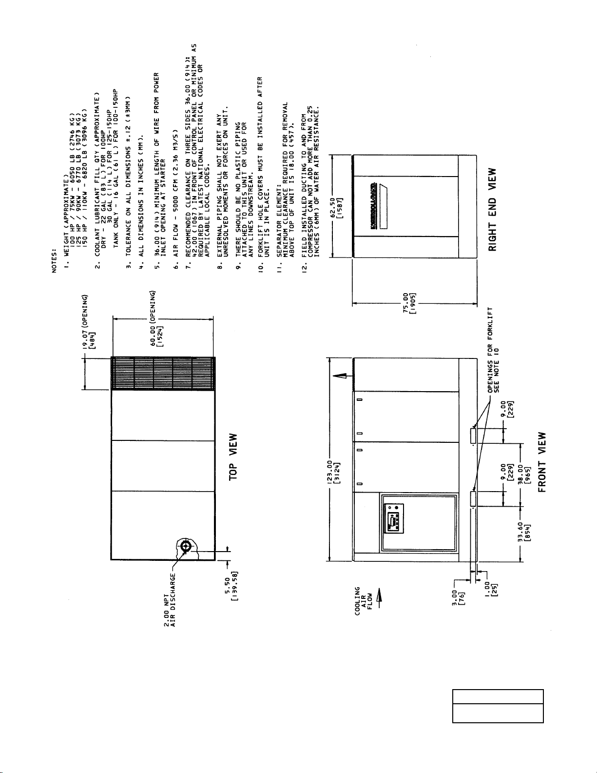
64
8.8 FOUNDATION PLAN -WATERCOOLED (CONTINUED)
100-150 HP/75-110 KW - TWO STAGE
39925326
REV C
Page 67
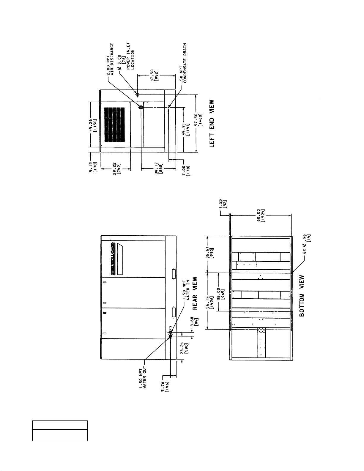
65
8.8 FOUNDATION PLAN -WATERCOOLED
100-150 HP/75-110 KW - TWO STAGE
39925326
REV C
Page 68
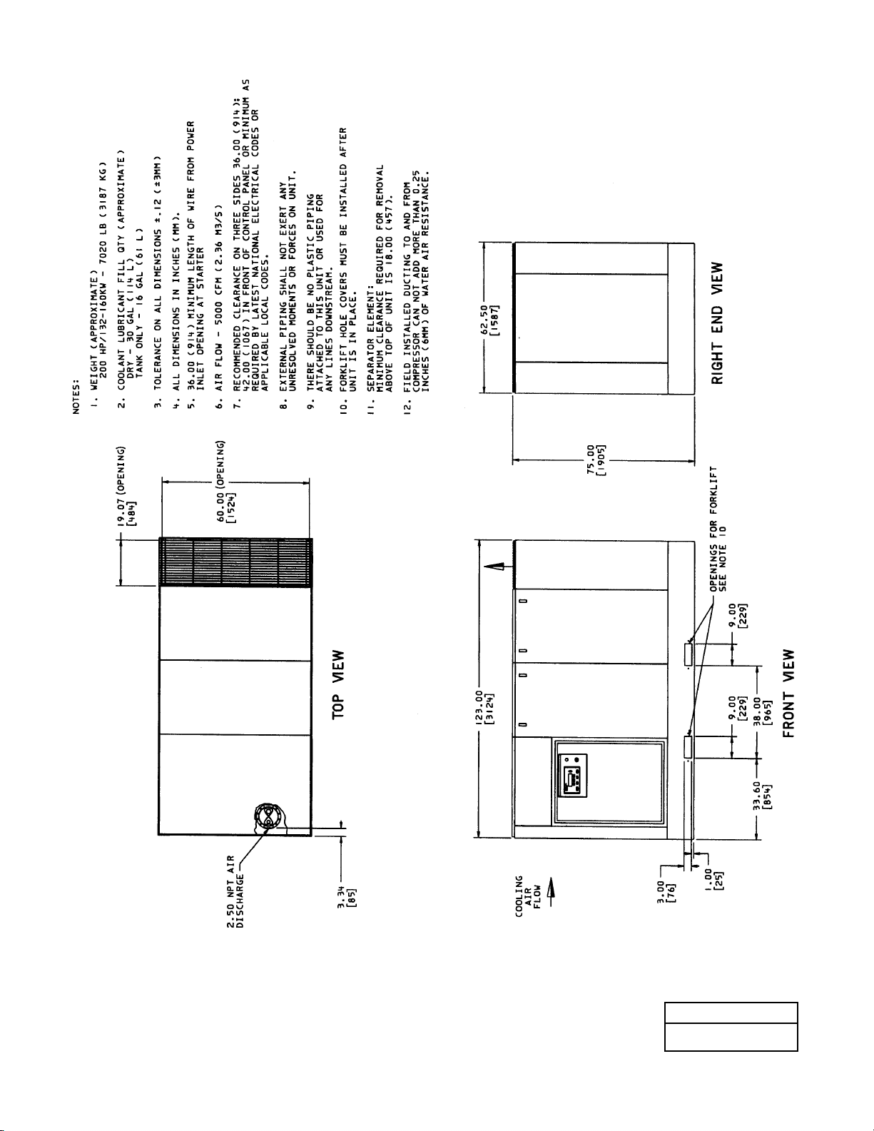
66
8.9 FOUNDATION PLAN -WATERCOOLED (CONTINUED)
200 HP/132-160 KW - TWO STAGE
39926340
REV C
Page 69
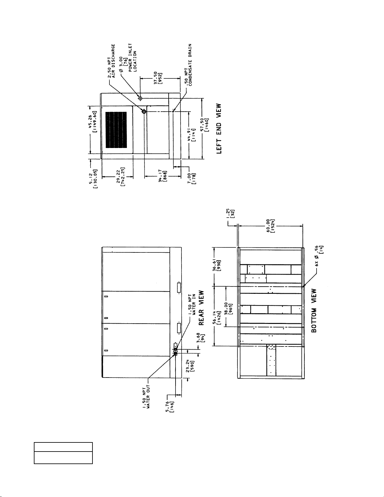
67
8.9 FOUNDATION PLAN -WATERCOOLED
200 HP/132-160 KW - TWO STAGE
39926340
REV C
Page 70
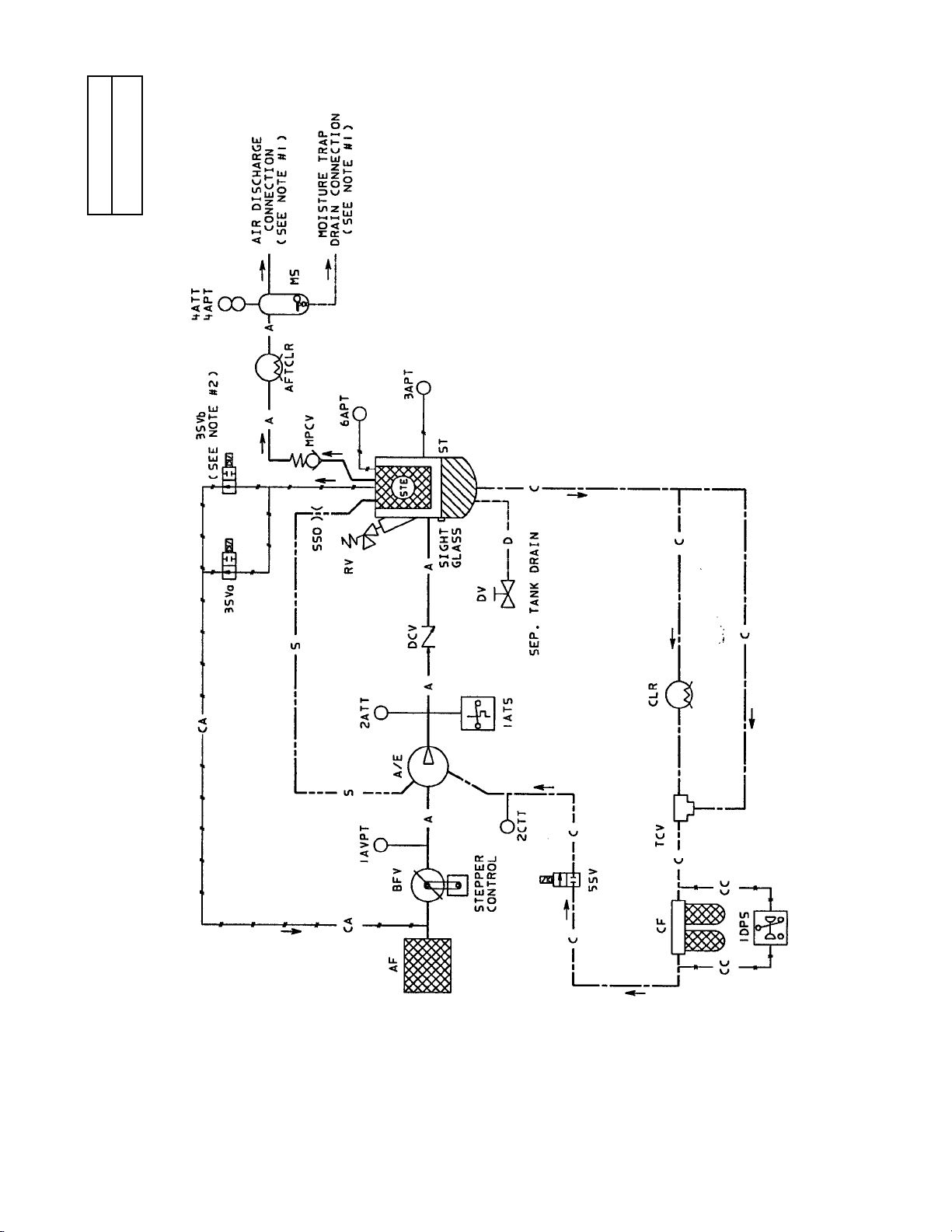
68
8.10 FLOW SCHEMATIC
AIRCOOLED - SINGLE STAGE
54579081
REV A
Page 71
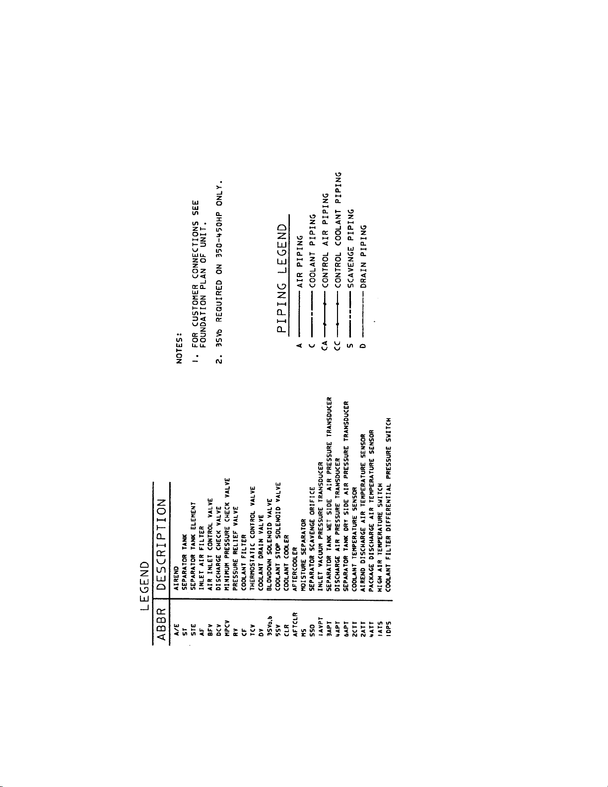
69
Page 72
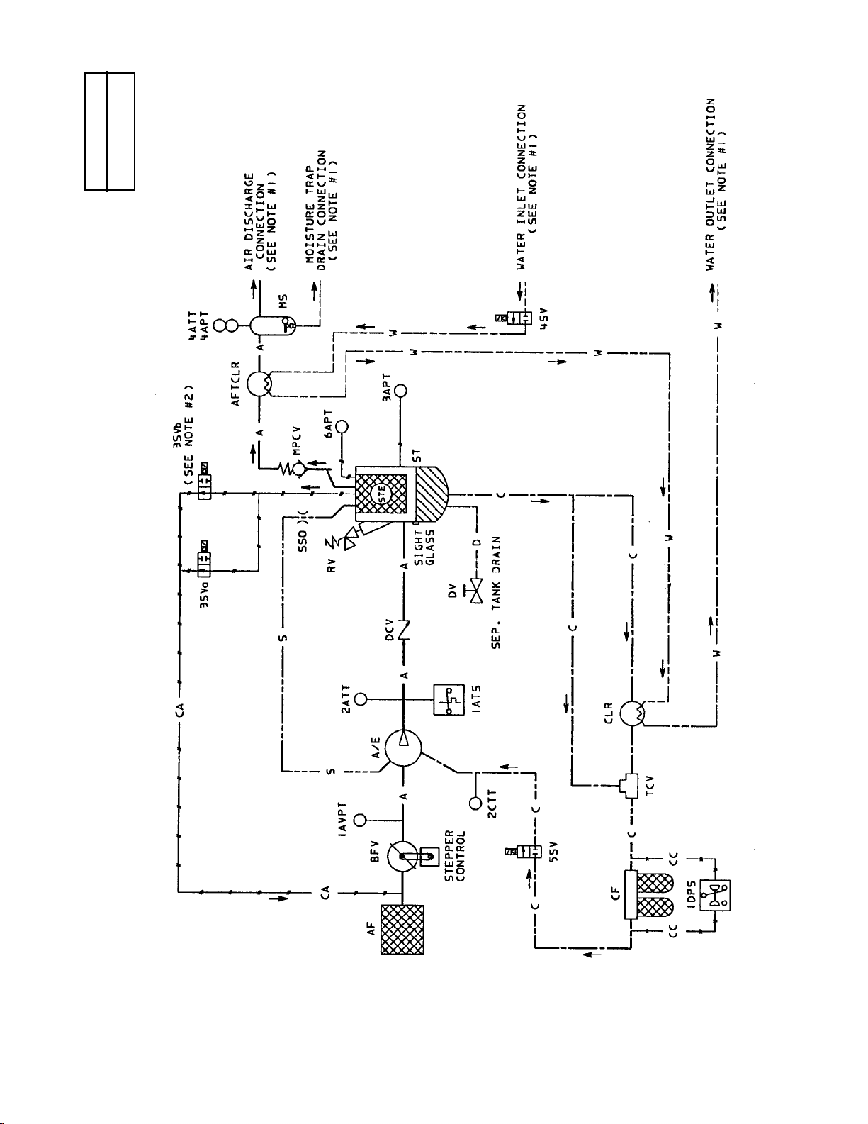
70
8.11 FLOW SCHEMATIC
WATERCOOLED - 90°F (32°C) - SINGLE STAGE
54579503
REV A
Page 73
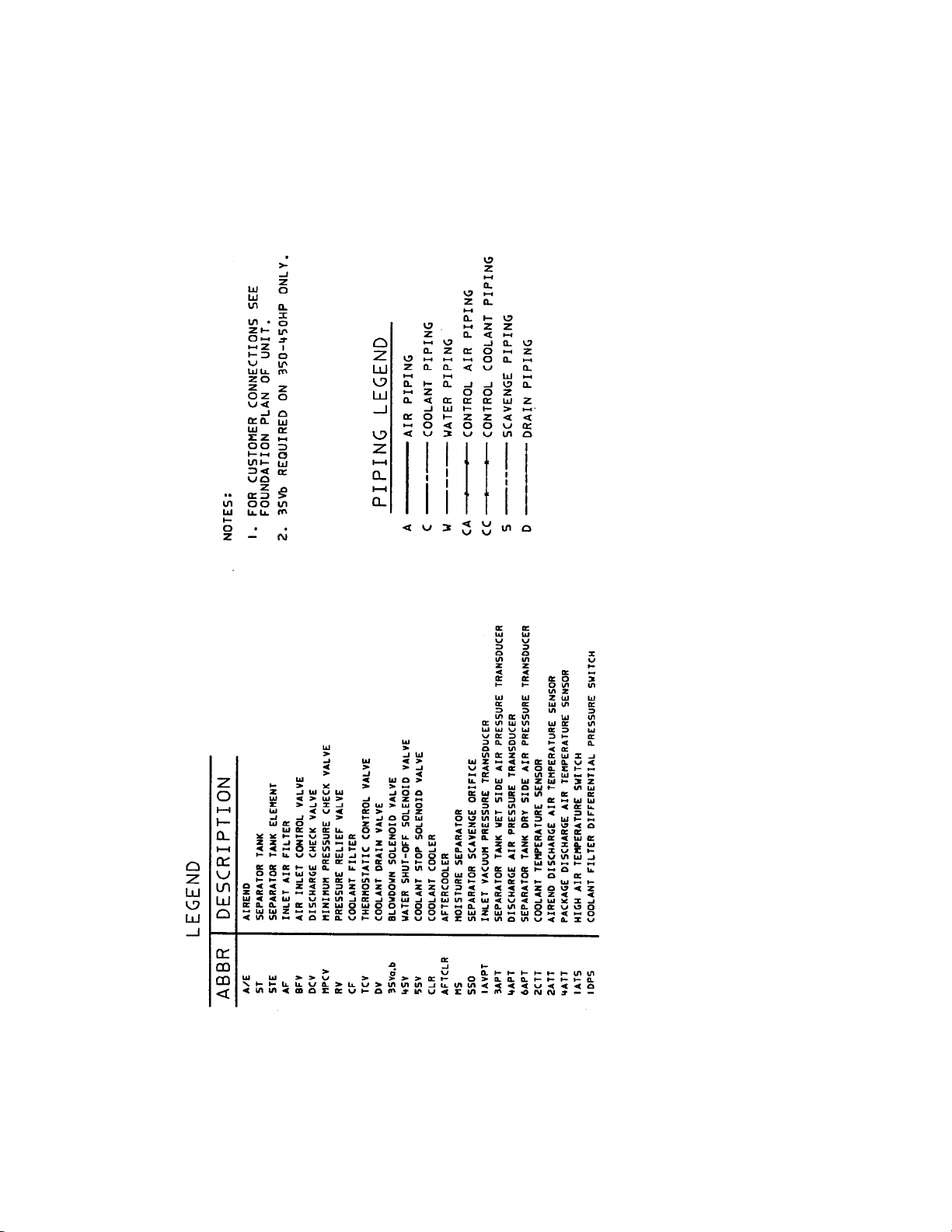
71
Page 74
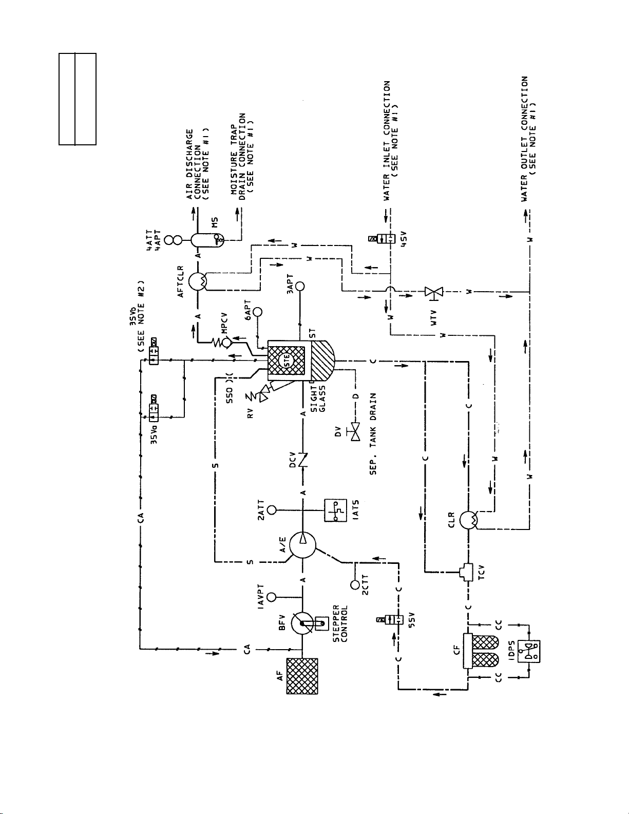
72
8.12 FLOW SCHEMATIC
WATERCOOLED - 115°F (46°) - SINGLE STAGE
54579511
REV A
Page 75
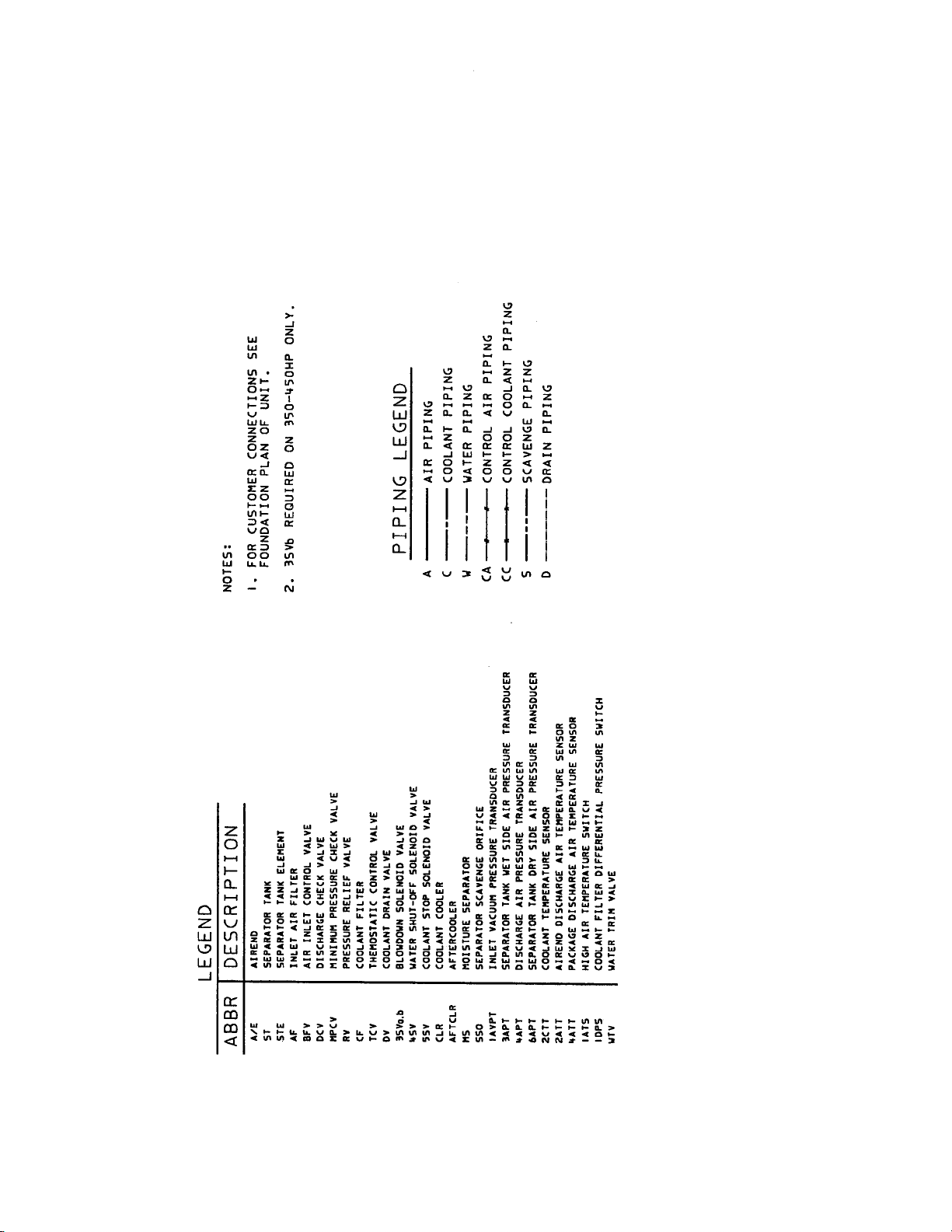
73
Page 76
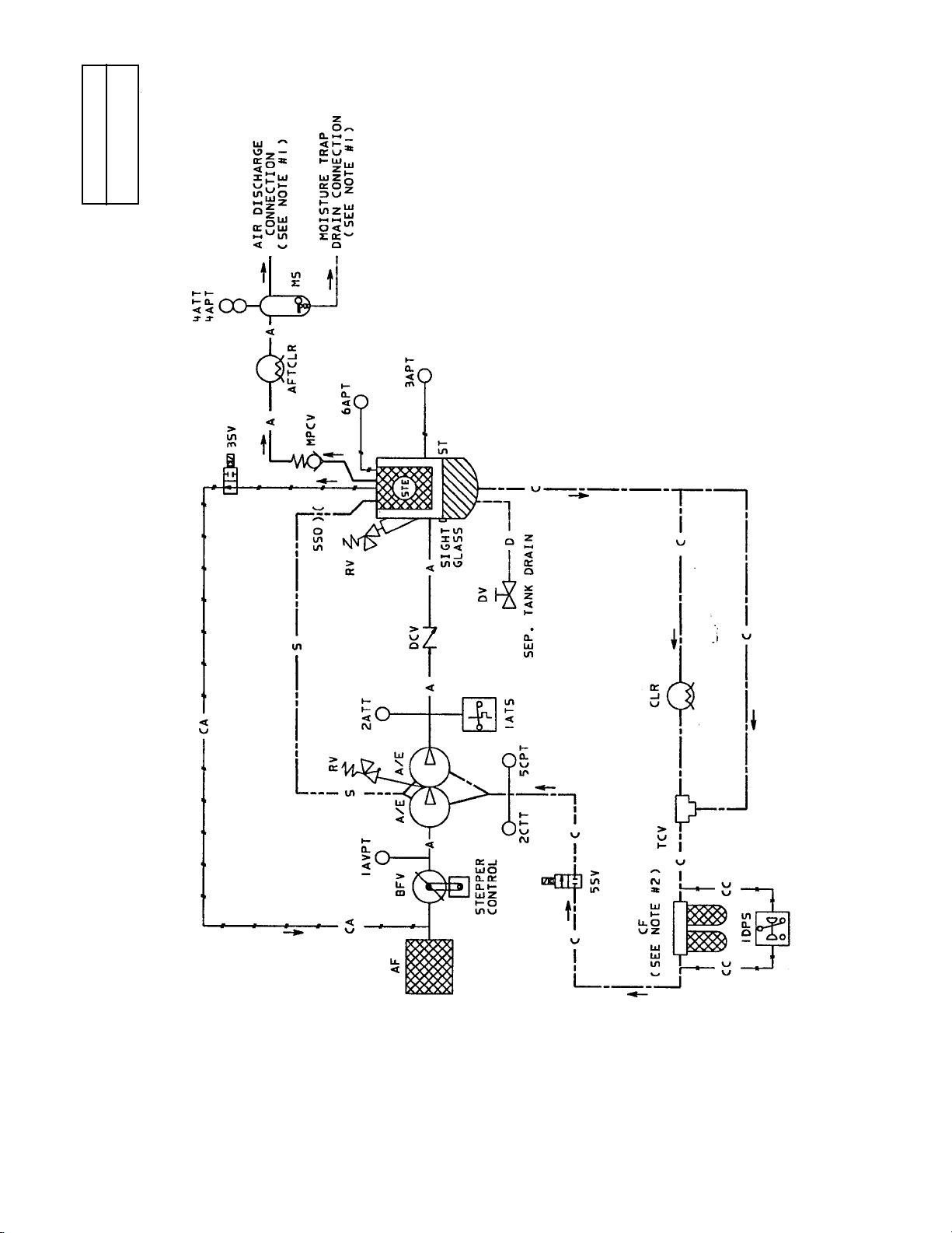
74
8.13 FLOW SCHEMATIC
AIR-COOLED - TWO STAGE
54579644
REV A
Page 77
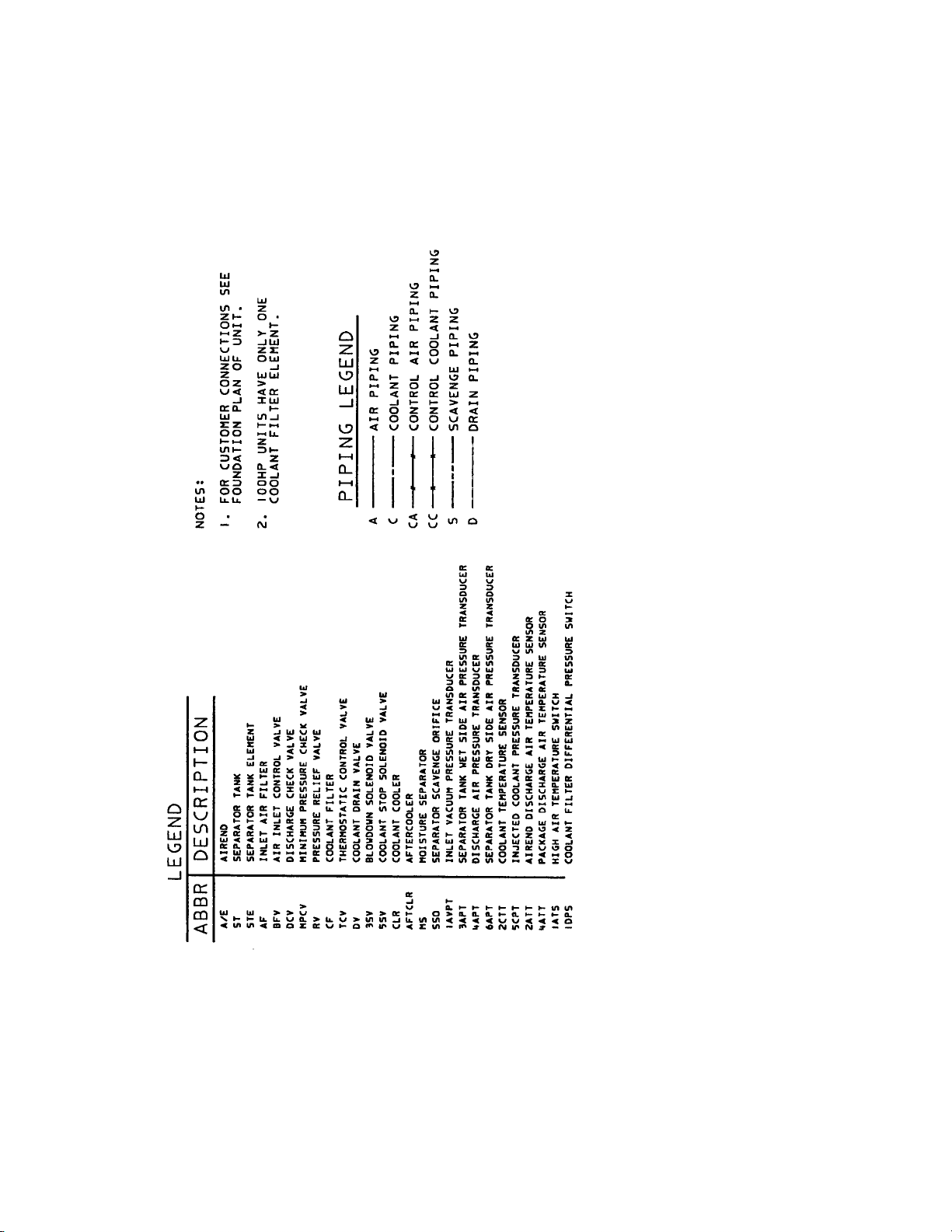
75
Page 78
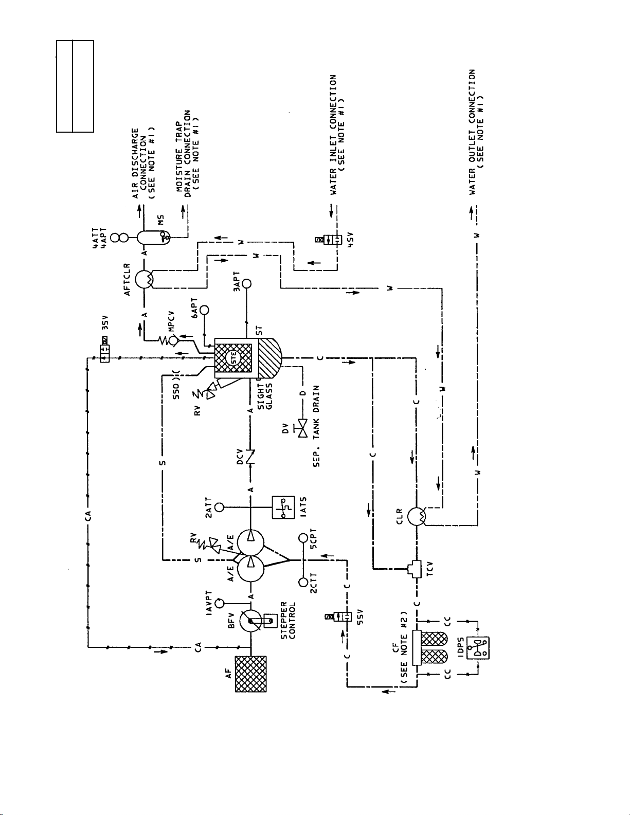
76
8.14 FLOW SCHEMATIC
WATERCOOLED 90°F (32°C)
TWO STAGE
54579693
REV A
Page 79
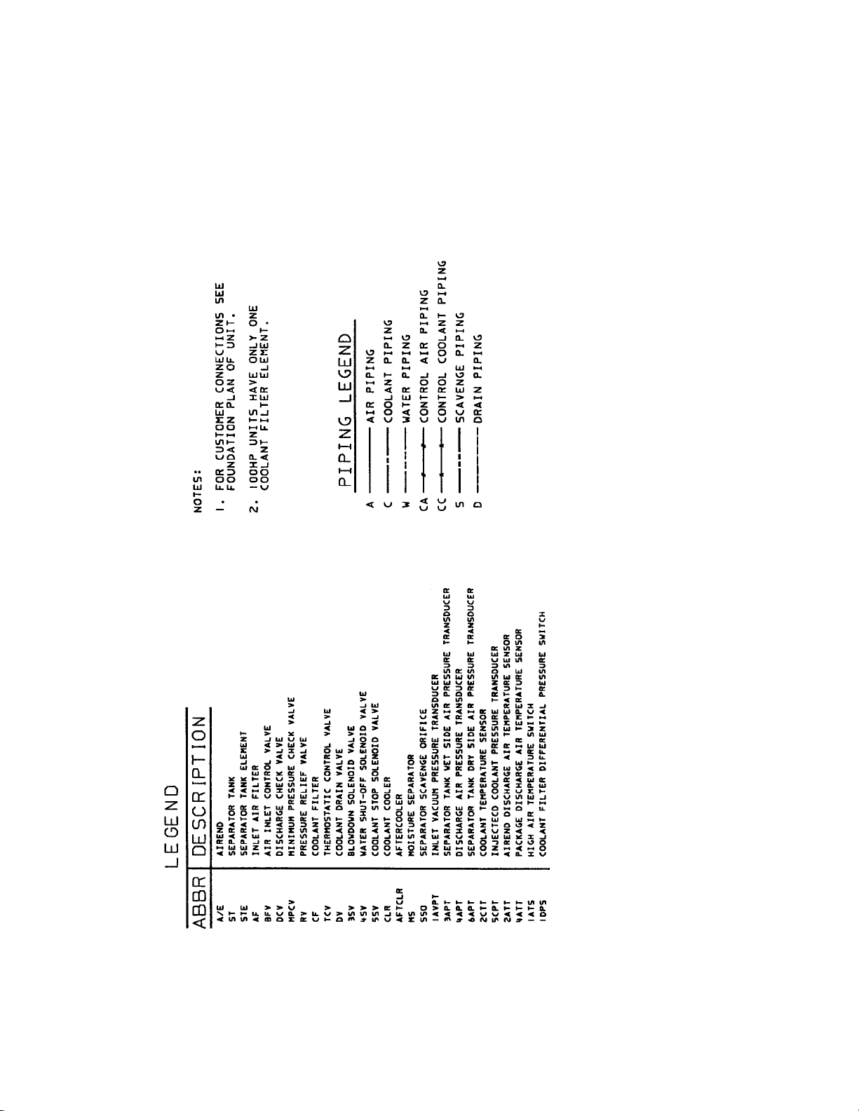
77
Page 80
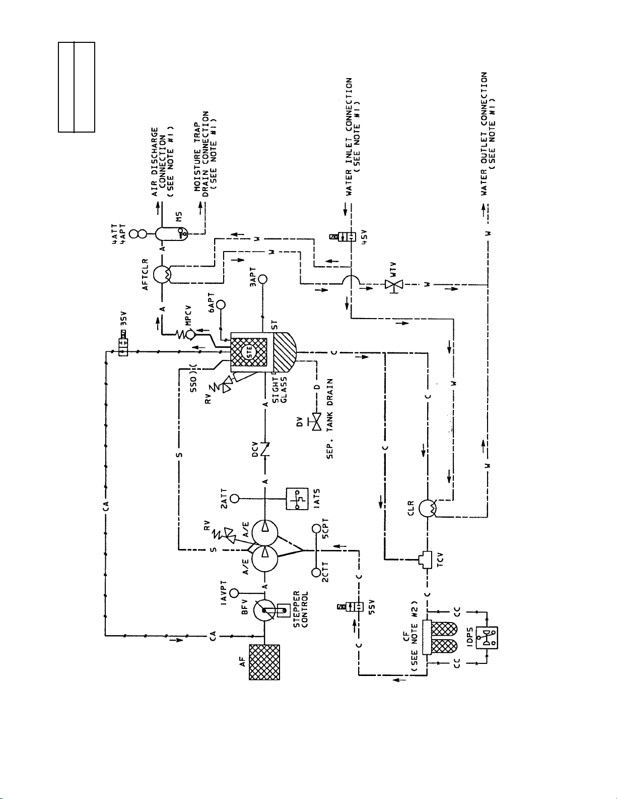
78
8.15 FLOW SCHEMATIC
WATERCOOLED 115°F (46°C)
TWO STAGE
54579727
REV A
Page 81
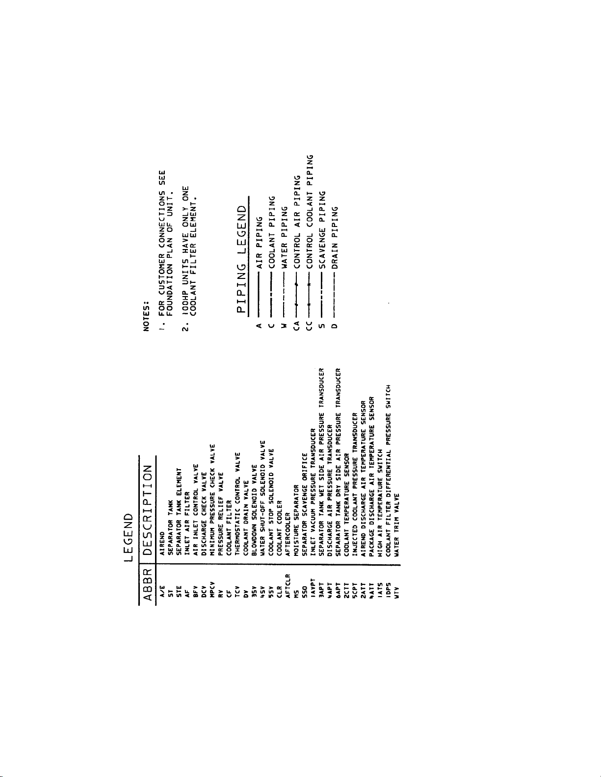
79
Page 82
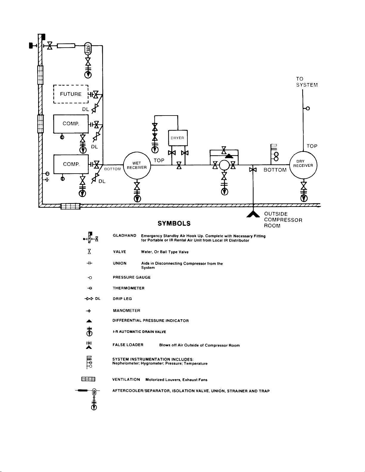
80
8.16 TYPICAL SYSTEM FLOW DIAGRAMS
TYPICAL SYSTEM FLOW
DIAGRAM
Page 83
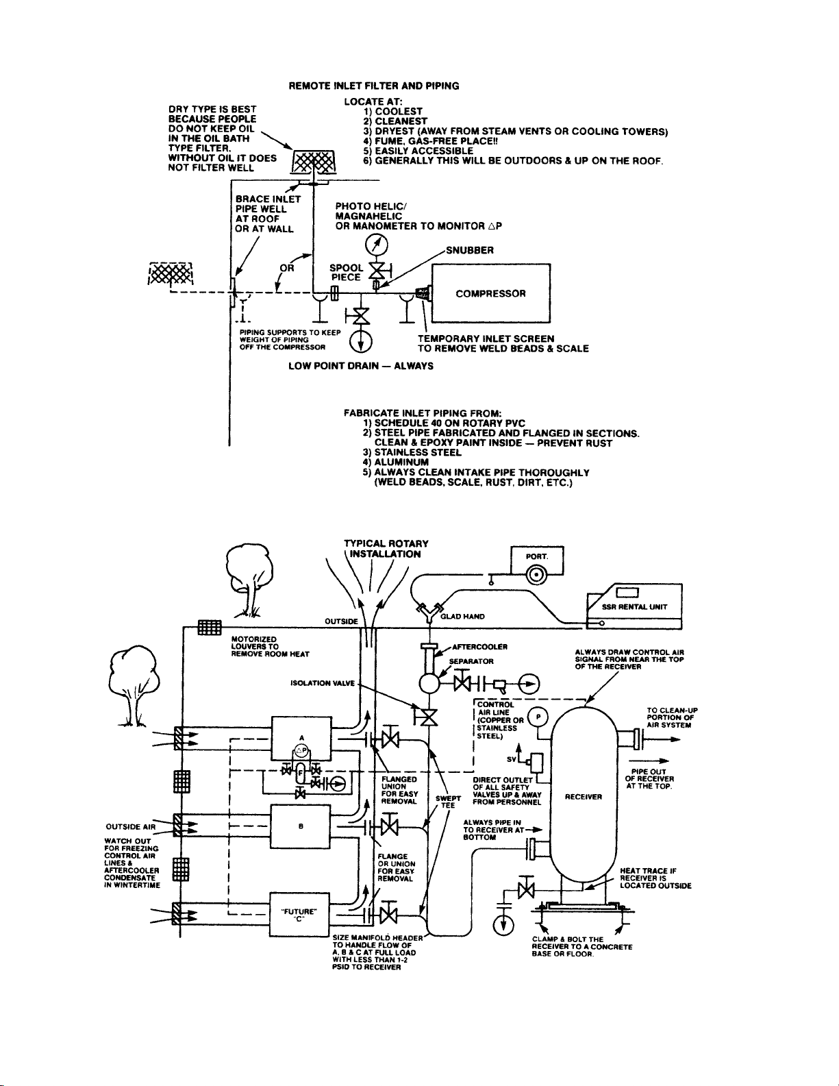
81
8.16 TYPICAL SYSTEM FLOW DIAGRAMS
Page 84
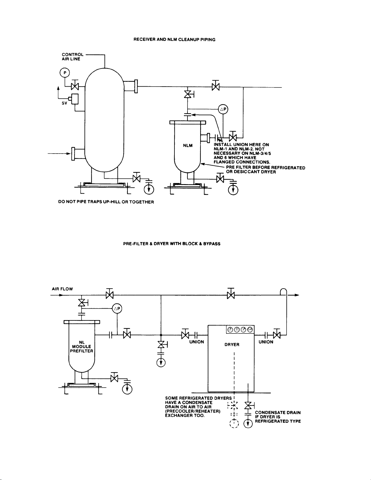
82
8.16 TYPICAL SYSTEM FLOW DIAGRAMS
Page 85
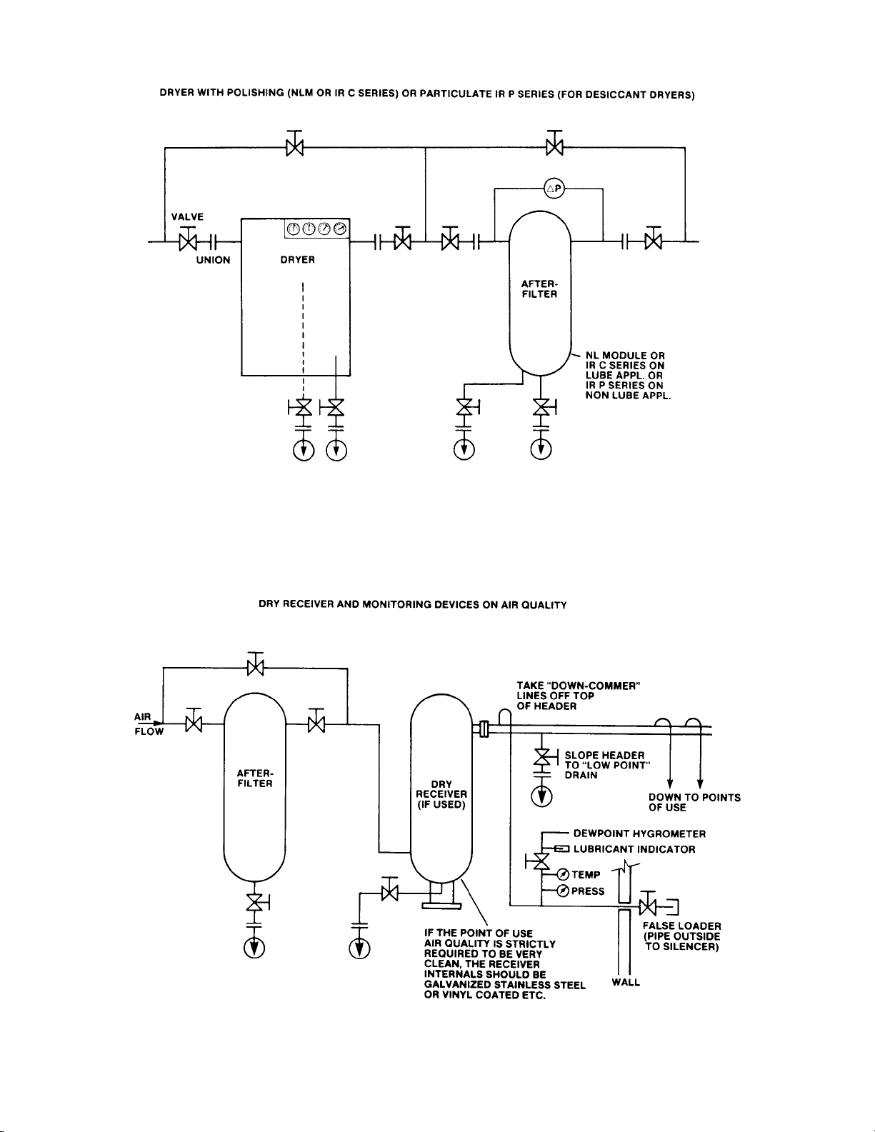
83
8.16 TYPICAL SYSTEM FLOW DIAGRAMS
Page 86
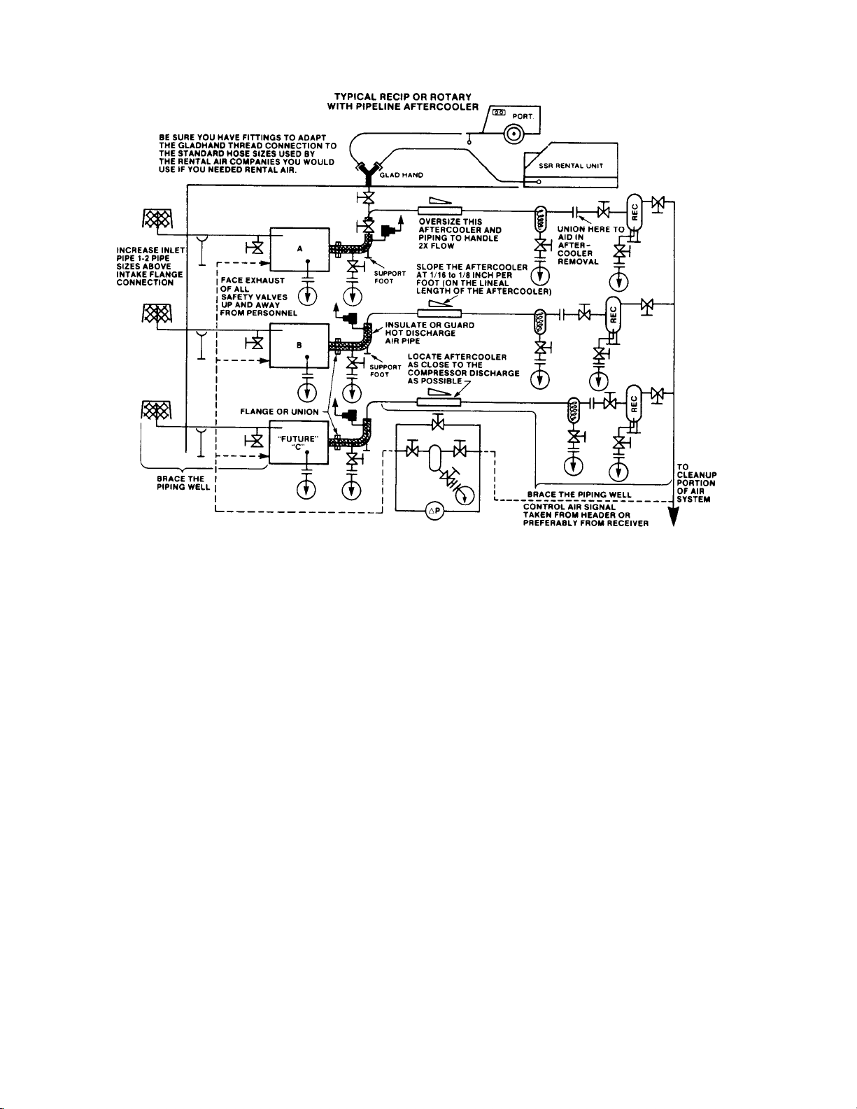
84
8.16 TYPICAL SYSTEM FLOW DIAGRAMS
Page 87

85
9.0 W A TER QU ALITY RECOMMENDATIONS
Water quality is often overlooked when the cooling
system of a water cooled air compressor is examined.
Water quality determines how effective the heat transfer
rate, as well as the flow rate will remain during the
operation life of the unit.It should be noted that the
quality of water used in any cooling system does not
remain constant during the operation of the system.The
water makeup is affected by evaporation, corrosion,
chemical and temperature changes, aeration, scale, and
biological formations. Most problems in a cooling system
show up first in a reduction in the heat transfer rate, then
in a reduced flow rate, and finally with damage to the
system.
There are many constituents in the water system that
must be balanced to have a good stable system.The
following is a list of the major components that should be
monitored:
SCALE
Scale formation inhibits effective heat transfer, yet it does
help prevent corrosion.Therefore, a thin uniform coating
of calcium carbonate is desired on the inner surfaces.
Perhaps the largest contributor to scale formation is the
precipitation of calcium carbonate out of the water.This is
dependent on temperature and pH.The higher the pH
value the greater the chance of scale formation.Scale
can be controlled with water treatment.
CORROSION
In contrast to scale formation is the problem of corrosion.
Chlorides cause problems because of their size and
conductivity. Low pH levels promote corrosion, as well as
high levels of dissolved oxygen.
FOULING
Biological and organic substances (slime) can also cause
problems, but in elevated temperature environments such
as cooling processes, they are not major concerns.If
they create problems with clogging, commercial shock
treatments are available.
To ensure good operation life and performance of the
compressor cooling system, the recommended
acceptable ranges for different water constituents are
included below:
PARAMETER
Corrosivity (hardness,
pH, total dissolved solids,
temperature at inlet,
alkalinity)
Iron
Sulfate
Chloride
Nitrate
Silica
Dissolved oxygen
Oil and grease
Ammonia
CONCENTRATION
Langelier Index
0 to 1
< 2 ppm
< 50 ppm
< 50 ppm
< 2 ppm
< 100 ppm
0 ppm
(as low as possible)
< 5 ppm
< 1 ppm
FREQUENCY OF ANALYSIS
Monthly
(if stable for 3 to 4 months,
analyze quarterly)
Monthly
Monthly
Monthly
Monthly
Monthly
Daily
(if stable, analyze weekly)
Monthly
Monthly
Page 88

86
Recommended equipment for on-site analysis includes a
thermometer, pH meter, and dissolved oxygen meter.
Dissolved oxygen and temperature must be measured
on-site and it is recommended that pH be measured
on-site. All other analyses should be performed by a
professional water quality analyst.The Langelier Index
(Ll) is calculated using the following equation and the
tables found on the following pages.
Ll = pH - (9.30 + Total Dissolved Solids char t value +
Temperature chart value ) + Hardness chart valve +
Alkalinity chart value)
The Ll is zero when the water is in chemical balance.If
the Ll is greater than zero, there is a tendency to form
scale. If the Ll is less than zero, the water tends to be
corrosive.
Dissolved oxygen may be controlled in closed cooling
towers.Several types of treatments are commercially
available to remove dissolved oxygen. For open cooling
towers, dissolved oxygen is not an easily controlled
parameter.Also, a filtration system is recommended for
the water going into the air compressor when using an
open cooling tower.
It should be noted that Ingersoll-Rand’s guidelines and
recommendations should be used in evaluating the water
systems and the problems that may occur in the normal
operation of our air compressors.If water problems
persist or are not covered above, you should consult a
professional.
Page 89
87
LANGELIER INDEX CHART VALUES
UNITS
0123456789
0 0.00 0.30 0.48 0.60 0.70 0.78 0.85 0.90 0.93
10 1.00 1.04 1.08 1.11 1.15 1.18 1.20 1.23 1.26 1.29
20 1.30 1.32 1.34 1.36 1.38 1.40 1.42 1.43 1.45 1.46
30 1.48 1.49 1.51 1.52 1.53 1.54 1.56 1.67 1.58 1.59
40 1.60 1.61 1.62 1.63 1.64 1.65 1.66 1.67 1.68 1.69
50 1.70 1.71 1.72 1.72 1.73 1.74 1.75 1.76 1.76 1.77
60 1.78 1.79 1.79 1.80 1.81 1.81 1.82 1.83 1.83 1.84
70 1.85 1.85 1.86 1.86 1.87 1.88 1.88 1.89 1.89 1.90
80 1.90 1.91 1.91 1.92 1.92 1.93 1.93 1.94 1.94 1.95
90 1.95 1.96 1.96 1.97 1.97 1.98 1.98 1.99 1.99 2.00
100 2.00 2.00 2.01 2.01 2.02 2.02 2.03 2.03 2.03 2.04
110 2.04 2.05 2.05 2.05 2.06 2.06 2.06 2.07 2.07 2.08
120 2.08 2.08 2.09 2.09 2.09 2.10 2.10 2.10 2.11 2 11
130 2.11 2.12 2.12 2.12 2.13 2.13 2.13 2.14 2.14 2.14
140 2.15 2.15 2.15 2.16 2.16 2.16 2.16 2.17 2.17 2.17
150 2.18 2.18 2.18 2.18 2.19 2.19 2.19 2.20 2.20 2.20
160 2.20 2.21 2.21 2.21 2.21 2.22 2.22 2.23 2.23 2.23
170 2.23 2.23 2.23 2.24 2.24 2.24 2.24 2.25 2.25 2.25
180 2.26 2.26 2.26 2.26 2.26 2.27 2.27 2.27 2.27 2.28
190 2.28 2.28 2.28 2.29 2.29 2.29 2.29 2.29 2.30 2.30
200 2.30 2.30 2.30 2.31 2.31 2.31 2.31 2.32 2.32 2.32
TENS
0102030405060708090
200 2.32 2.34 2.36 2.38 2.40 2.42 2.43 2.43 2.46
300 2.48 2.49 2.51 2.52 2.53 2.54 2.56 2.57 2.58 2.59
400 2.60 2.61 2.62 2.63 2.64 2.65 2.66 2.67 2.68 2.69
500 2.70 2.71 2.72 2.72 2.73 2.74 2.75 2.76 2.76 2.77
600 2.78 2.79 2.79 2.80 2.81 2.81 2.82 2.83 2.83 2.84
700 2.85 2.85 2.86 2.86 2.87 2.88 2.88 2.89 2.89 2.90
800 2.90 2.91 2.91 2.92 2.92 2.93 2.93 2.94 2.94 2.95
900 2.95 2.96 2.96 2.97 2.97 2.98 2.98 2.99 2.99 3.00
UNITS
02468
30 2.60 2.67 2.54 2.81
40 2.48 2.45 2.43 2.40 2.37
50 2.34 2.31 2.28 2.25 2.22
60 2.20 2.17 2.14 2.11 2.09
70 2.06 2.04 2.03 2.00 1.97
80 1.95 1.92 1.90 1.88 1.86
90 1.84 1.82 1.80 1.78 1.76
100 1.74 1.72 1.71 1.09 1.67
110 1.05 1.64 1.62 1.60 1.58
120 1.67 1.63 1.53 1.51 1.50
130 1.48 1.46 1.44 1.43 1.41
140 1.40 1.38 1.37 1.35 1.34
150 1.32 1.31 1.29 1.28 1.27
160 1.26 1.24 1.23 1.22 1.21
170 1.19 1.18 1.17 1.10
TENS
TENSHUNDREDS
Alkalinity (ppm)
Temperature (°F)
50 .07
75 .08
100 .10
150 .11
200 .13
300 .14
400 .16
600 .18
800 .19
1000 .20
TOTAL SOLIDS (PPM)
Total dissolved solids (ppm)
UNITS
01234 56789
0 0.08 0.20 0.30 0.38 0.43 0.51 0.56
10 0.60 0.64 0.68 0.72 0.73 0.78 0.81 0.83 0.86 0.88
20 0.90 0.92 0.94 0.96 0.98 1.00 1.02 1.03 1.05 1.06
30 1.08 1.09 1.11 1.12 1.13 1.15 1.16 1.17 1.18 1.19
40 1.20 1.21 1.23 1.24 1.25 1.26 1.26 1.27 1.28 1.29
50 1.30 1.31 1.32 1.33 1.34 1.34 1.35 1.36 1.37 1.37
60 1.38 1.39 1.39 1.40 1.41 1.42 1.42 1.43 1.43 1.44
70 1.45 1.45 1.46 1.47 1.47 1.48 1.48 1.49 1.49 1.50
80 1.51 1.51 1.52 1.52 1.53 1.53 1.54 1.54 1.55 1.55
90 1.56 1.56 1.57 1.57 1.58 1.58 1.58 1.59 1.59 1.60
100 1.60 1.61 1.61 1.61 1.62 1.62 1.63 1.63 1.64 1.64
110 1.64 1.65 1.65 1.66 1.66 1.66 1.67 1.67 1.67 1.68
120 1.68 1.68 1.69 1.69 1.70 1.70 1.70 1.71 1.71 1.71
130 1.72 1.72 1.72 1.73 1.73 1.73 1.74 1.74 1.74 1.75
140 1.75 1.75 1.75 1.76 1.76 1.76 1.77 1.77 1.77 1.78
150 1.78 1.78 1.78 1.79 1.79 1.79 1.80 1.80 1.80 1.80
160 1.81 1.81 1.81 1.81 1.82 1.82 1.82 1.82 1.83 1.83
170 1.83 1.84 1.84 1.84 1.84 1.85 1.85 1.85 1.85 1.85
180 1.86 1.86 1.86 1.86 1.87 1.87 1.87 1.87 1.88 1.88
190 1.88 1.88 1.89 1.89 1.89 1.89 1.89 1.90 1.90 1.90
200 1.90 1.91 1.91 1.91 1.91 1.91 1.92 1.92 1.92 1.92
TENS
0102030405060708090
200 1.92 1.94 1.96 1.98 2.00 2.02 2.03 2.03 2.06
300 2.08 2.09 2.11 2.12 2.13 2.13 2.16 2.17 2.18 2.19
400 2.20 2.21 2.23 2.24 2.23 2.26 2.26 2.27 2.28 2.29
500 2.30 2.31 2.32 2.33 2.34 2.34 2.35 2.36 2.37 2.37
600 2.38 2.39 2.39 2.40 2.41 2.42 2.42 2.43 2.43 2.44
700 2.45 2.45 2.46 2.47 2.47 2.48 2.48 2.49 2.49 2.50
800 2.51 2.51 2.52 2.52 2.53 2.53 2.54 2.54 2.55 2.55
900 2.56 2.56 2.57 2.57 2.58 2.58 2.58 2.59 2.60 2.60
TENSHUNDREDS
Hardness (ppm)
Page 90
88
DATE RUN TIME WORK DONE QTY. UNIT WORK
(HOURS) MEASURE BY
10.0 MAINTENANCE RECORD
Page 91
89
DATE RUN TIME WORK DONE QTY. UNIT WORK
(HOURS) MEASURE BY
MAINTENANCE RECORD
Page 92
90
DATE RUN TIME WORK DONE QTY. UNIT WORK
(HOURS) MEASURE BY
MAINTENANCE RECORD
Page 93
91
DATE RUN TIME WORK DONE QTY. UNIT WORK
(HOURS) MEASURE BY
MAINTENANCE RECORD
 Loading...