

U s e r G u i d e
Contents
iWL2xx Wireless Series
1. Introduction ________________________________________________ 4
2. Presentation________________________________________________ 5
2.1. Content of the box ______________________________________________________ 5
2.1 .1. Terminal________ _______________ _______________ ______________ ______________ 5
2.1 .2. Base ( opti onal ) ___ _______________ _______________ __________ _______________ __ 5
2.2. Overview of the iWL2XX__________________________________________________6
2.3. Keyboard details and functionality _________________________________________ 7
3. Use of the terminal __________________________________________ 7
3.1. Adjusting contrast (B&W display only)______________________________________ 7
3.2. Switching off the terminal ________________________________________________8
3.3. Reading cards___________________________________________________________8
3.4. Installing the terminal on the base _________________________________________9
4. Installation _________________________________________________ 10
4.1. Recommendations _____________________________________________________ 10
4.2. Terminal connection s ___________________________________________________ 10
4.3. Installing Modules_______________________________________________________11
4.3.1. SAM1/SAM2/SIM _______ __________ _______________ ______________ _____________ 11
4.3.2. MicroSD Memory Card____________ _______________ _______________ _____________ 11
INGENICO – 192 avenue Charles de Gaulle – 92200 Neuill y sur Seine - FRANCE
Tél. 33(0)1 46 25 82 00 - Fax 33 (0)1 47 72 56 95
www.ingenico.com
4.4. Paper roll _____________________________________________________________ 13
4.4.1. Mains characteristics of INGENICO paper roll___ _______________ _______________ _____ 13
4.4.2. Installing paper roll_ _______________ _________________ ____________ _________ ____14
4.5. Battery _______________________________________________________________ 15
4.5.1. Main characteristics _________ _______________ ________ ____________ _________ ____ 15
4.5.2. Installing the battery _______ _______________ ________ _____________ _____________ 15
4.5.3. Charging the battery ___ __________ _______________ _______________ _____________ 15
4.5.4. Changing the battery _____________ _______________ _________ _______________ ____ 15
5. Base ______________________________________________________ 15
5.1.1. Base rear connecti ons __________ _______________ ________ _________ ____________ _15
iWL2xx Wireless Series • 2/32 Copyright © 2011 Ingen ico
900003061 R11 000 04/1050 All rights reserved
5.1.2. Base downside connections ______________________ ________ _________ ____________ 15
5.1.3. Fasten your b ase on desk __________ _______________ ____________ _______________ _15
6. Recommendations ___________________________________________ 15
6.1. Safety ________________________________________________________________ 15
6.2. Security of your terminal ________________________________________________ 15
6.3. Telephone call _________________________________________________________ 15
7. Standards __________________________________________________ 15
8. Troubleshooting_____________________________________________ 15
9. Annex _____________________________________________________ 15
1. Introduction
We hope that you will be fully satisfied with your new terminal iWL2XX. This terminal is
available in different models. Please select by yourself in this documentation items related
to your model.
Read this guide to un derstand and make the best use of your terminal.
It presents you the necessary information about use, installation, maintenance, safety and
security recommendations.
WARRANTY / SECURITY
Use only the power supply included with the product to ensure best performance and
safety. Maintenance should only be provided by Ingenico authorized technician.
Failu re to comply with these instructions will void the manufacturer’s responsibility.
This symbol indicates an important Warning.
This symbol indicates a piece of advice.
iWL2xx Wireless Series • 3/32 Copyright © 2011 Ingenico
900003061 R11 000 04/1050 All rights reserved
iWL2xx Wireless Series • 4/32 Copyright © 2011 Ingenico
900003061 R11 000 04/1050 All rights reserved
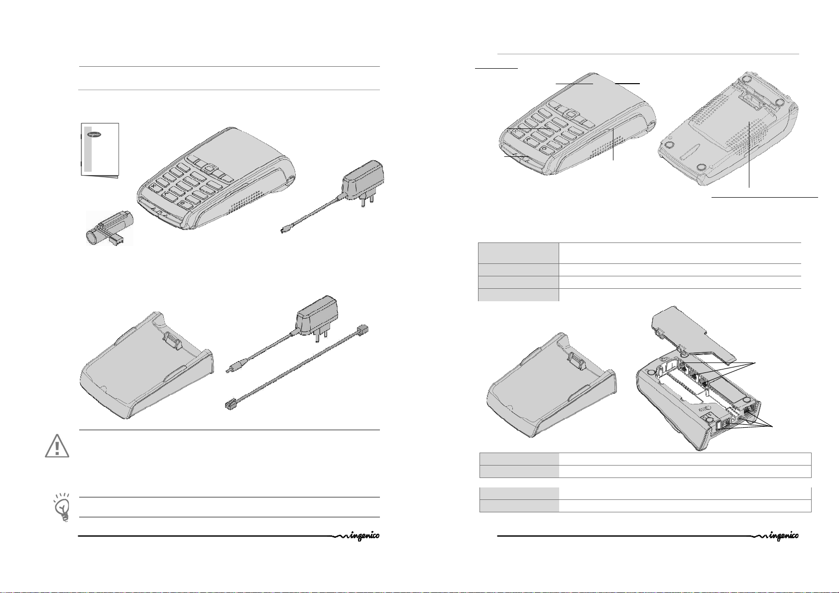
IWL2XX terminal uni t
Base
mains network
A battery pack disconnected
(with base modem)
A user’s guide
Easy loading printer
Large graphi c display
Terminal
unit
E
xternal
Base unit
2. Presentation
2.1. Content of the box
2.1.1.
Terminal
equipped with a paper roll
2.1.2.
Base ( optional )
A power supply unit that
connect the base to the
WARNING
The power supply unit provided with your equipment is specially desig ned for Ingenico
terminals. Do not use any other power supply. The use of a power supply with apparently
similar voltage/current characteristics may damage your terminal.
This product can be powered by an IT network only in Norway
In Switzerland, plug must complying with SEV 1011 or IEC 60884-1
ADVICE
Keep the packaging. It must be re-used when ever the terminal is shipped.
Power travel adapter
(when no base)
A telephone cab le
2.2. Overview of the iWL2XX
Backlit
keyboard
Smart
card reader
Weight (without paper
roll nor battery)
Dimensions (L x w x h) 150x76x44mmfor the R25 model and 164,5x76x53,5mm for the R40 model
Mains ne twork 100- 240VAC / 50-60 Hz - Class II equipment
Connections on terminal Micro USB AB serial link
290g for the R25 model and 310g for the R40 model
Base
Weight About 150g
Dimensions (L x w x h) 140,7x87,7x45 mm
Power supply unit
Weight About 100g
2pole sockets 1A (traveller power supply) or 1 A (base power supply)
Power supply units are specially fitted for INGENICO terminals.
Magnetic card
reader
Compartment where are located :
• the battery pack
• the SAM1/SAM2/SIM connector
• the module microSD
nd
• the 2
Smart card reader
External
links
links
iWL2xx Wireless Series • 5/32 Copyright © 2011 Ingenico
900003061 R11 000 04/1050 All rights reserved
iWL2xx Wireless Series • 6/32 Copyright © 2011 Ingen ico
900003061 R11 000 04/1050 All rights reserved
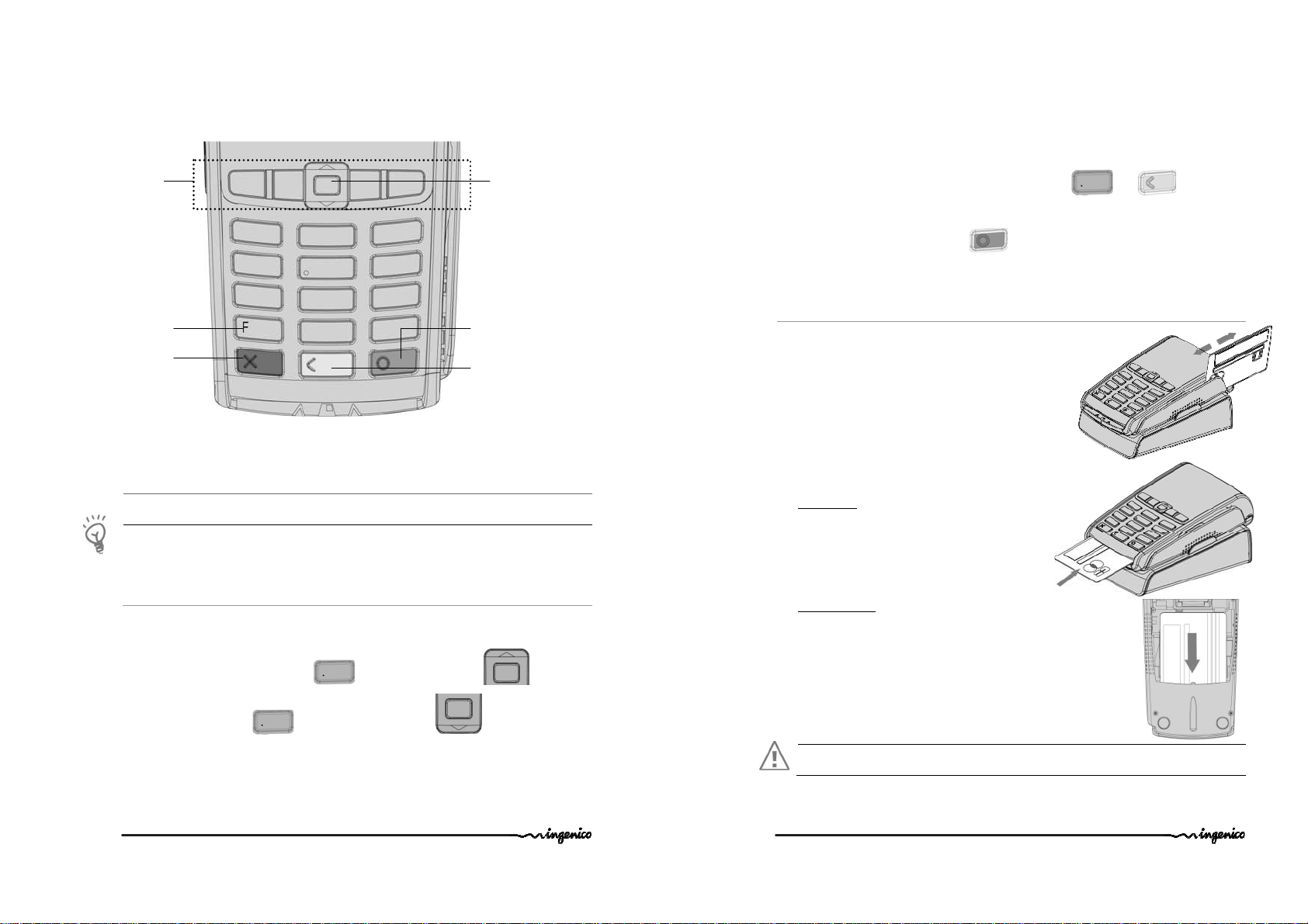
2.3. Keyboard details and functionality
Some keys can have other functions according to the applications that are in the terminal.
The navigation keys
navigate in the
terminal menus
The function key
accesses the different
application menus
The red key cancels the
procedure in progres s
3. Use of the terminal
ADVICE
Before using the terminal, always check if the roll of paper is present.
3.1. Adjusting contrast (B&W display only)
If you wish to increase or to decrease the contrast of the characters displayed on black and
white display, press simultaneously and navigator UP key in order to
increase the contrast, or and navigator DOWN key in order to decrease
the contrast.
Keep pressing the keys as long as necessary.
iWL2xx Wireless Series • 7/32 Copyright © 2011 Ingenico
900003061 R11 000 04/1050 All rights reserved
Up/down and OK navigator
The green key validates input
selections and information.
It is als o used to switch on the
terminal
The yellow key cancels the last
character it can also advance
the paper a few centimetres if
pressed for a long time (more
than 2 se conds)
3.2. Switching off the terminal
If the battery is empty and the terminal in use is removed from its base, the terminal
automaticall y shuts off.
It may also be forced stopped by pressing simultaneously and (yellow key)
for one second.
In order to restart the terminal, press (green key) on the keyboard.
3.3. Reading cards
Magnetic stripe card
The card can be read either from bottom to top or from
topto bottom, with the stripe facing the terminal.
Use a regular movement in order to ensu re a reliable
card reading.
Smart card
• Card reader : insert the card horizontally with
the metal chip facing upward and leave in
position throughout the transact ion.
nd
• 2
card reader (Optional) : is located under
terminal trapdoor (on back of the terminal). Insert the card up
side down, magnetic stripe visible.
Warning
Switch off the terminal before opening the trapdoor.
iWL2xx Wireless Series • 8/32 Copyright © 2011 Ingen ico
900003061 R11 000 04/1050 All rights reserved
4 leds
(B&W display only)
Acti ve
zone
Contactless (optional)
• Bring the card firmly up to the active zone. Keep the
card close to the reader during the transaction
•
The 4 LEDs indicate transaction processing (as shown
on the picture) . On color screen terminal virtual LEDs
are displayed.
The terminal behavior for the cardho lder may depend on:
• The terminal environment
• Local usage (language…)
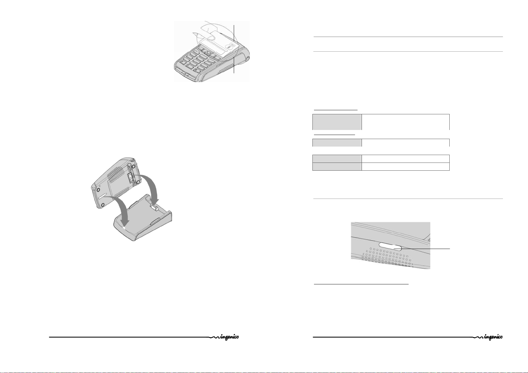
3.4. Installing the terminal on the base
Connecting the terminal on the base
Place the iWL2XX between the flanges on its base so that the contacts of the iWL2XX
engage on the contacts provided on the base (see picture below).
Using the modem base (if modem fitted on your base)
Once installed, the base modem is designed to always be plugged into the mains network
and be connected to a telephone line. The telephone line should not be shared.
The portable may be placed back on its base after each transaction. It must be placed on its
modem base when telephone network is used for : authorization request, remote
collection, downloading.
4. Installation
4.1. Recommendations
Location of the iWL2xx
Place the base on flat surface near an electric socket and, if modem option, a telephone
socket. The terminal should be placed far from any very hot zones, protected from
vibrations, dust, damp and electromagnetic radiation (computer screen , anti-theft barrier
etc.).
The terminal must not be fixed to a counter in such a way that a user cannot pick up the
terminal and use h is/her body to conceal the PIN when it is requested.
Operating conditions
Ambiant temperature from -10°C to +40°C
Max relative humidity 85% at +40°C
Charging conditions
Ambiant temperature from 0°C to +40°C
Storage conditions
Ambient temperature from -20°C to +55°C
Max relative humidity 85% at +55°C
4.2. Terminal connections
• There is an USB connector (microAB) on the left side of the iWL2XX Wireless
terminal (see below picture). This connector manages Host or Slave connexions.
*MicroAB connector durability : up to 10000 mating cycl es
• The terminal supports USB Keys with FAT16 or FAT32
• The USB Key has to be used with an USB adapter (r efers to accessories section)
USB (microAB)
Connector used for PC,
travel charger adapter, USB
Key, etc…)
iWL2xx Wireless Series • 9/32 Copyright © 2011 Ingen ico
900003061 R11 000 04/1050 All rights reserved
iWL2xx Wireless Series • 10/32 Copyright © 2011 Ingenico
900003061 R11 000 04/1050 All rights reserved

4.3. Installing Modules
Micro
SD card
4.3.1.
SAM1/SAM2/SIM
CAUTION :
Switch off the terminal before opening the trapdoor.
The SAM/SIM connectors are located inside the terminal,
in a closed compartment.
• Turn the terminal and unclip the trapdoor by pushing on the
clips with your nails as sh own with the arrows on the picture
• SAM1, SAM2 and SIM are identified by the engraved marks on
the lower housing
• When introducing a SAM/SIM in its slot, be sure to put the
cut corner as indicated on the picture
• Cl ose the trapdoor.
TIP
Use a piece of adhesive tape to grip th e SAM for easier and faster removal.
4.3.2.
MicroSD Memory Card
CAUTION :
Switch off the terminal before opening the trapdoor.
MicroSD connector is located inside the terminal , in a closed
compartment.
To install a MicroSD Memory Card :
• Turn the terminal and unclip the trapdoor by pushing on the
clips with your nails as sh own with the arrows on the picture
• Remove battery pack (disconnecting is not necessary).
• Insert the MicroSD Memory Card into the connector slot as
shown on the figure.
Be sure to put the MicroSD contacts downside and the cut
corner as indicated on the figure.
• Close the trapdoor
The terminal supports MicroSD up to 32GB
iWL2xx Wireless Series • 11/32 Copyright © 2011 Ingen ico
900003061 R11 000 04/1050 All rights reserved
To remove a MicroSD Memory Card :
• Turn the terminal and unclip the trapdoor by pushing on the clips
with your nails as sh own with the arrows on the picture
• Remove battery pack (disconnecting is not necessary).
• Remove the MicroSD Memory Card. MicroSD connector has
push/pull ability . Push on MicroSD card edge to remove it.
• Close the trapdoor
SIM
Cut corner
position
SAM1
SAM2
Cut corner
po sition
iWL2xx Wireless Series • 12/32 Copyright © 2011 Ingen ico
900003061 R11 000 04/1050 All rights reserved

4.4. Paper roll
4.4.1.
Mains characteristics of INGENICO paper roll
Depending on iWL model two paper roll can be u sed:
R40 paper roll Characteristics Precisions
Colour White
Width 58 mm
Diameter 40 mm
Length About 18 metres
R25 paper roll Characteristics Precisions
Colour White
Width 58 mm
Diameter 25 mm
Length About 9 metres
• The thermal paper can be deteriorated by poor storage conditions, so we
recommend you to avoid :
– storage in h ot wet places (near air-conditioner, humidity higher than 85%)
– exposure to sunlight or ultraviolet for long periods
– contact with organic solvents (solvent type adhesive)
– direct contact with materials containing plasticizers (PVC transparent
folders or envelopes)
– direct contact with «diazo» papers
– direct contact with water
– Rubbing or pressing the paper too strongly
• Recommended paper:
AF50KS (Jujo), or F5041 (Mitsubishi), or TK50KS (Nippon_Paper), or equivalent.
WARNING
For best product performance, only use heat sensitized paper approved by Ingenico.
WARNING
Switch off the terminal prior to installing a paper roll.
Use only paper approved by Ingenico.
The use of non approved paper is likel y to damage the printer of your terminal.
4.4.2.
Installing paper roll
• Open the paper compartment by lifting the catch located at the rear of the iWL2XX and
pull the cover to the rear of the terminal.
• Insert the paper roll in the compartment following the directions shown on the below
picture
• Pull the paper up to the top of the terminal
• Maintain the paper and close the cover
• Press simultaneously on both upper corners of the pap er flap, as shown by red arrows
on picture, until it clips into position
ADVICE
If you insert a new R40 paper roll, tear off th e first length (one complete turn to avoid
printing on adhesive tape footprint). This is not necessary on R25 paper roll as it has no
tape.
iWL2xx Wireless Series • 13/32 Copyright © 2011 Ingen ico
900003061 R11 000 04/1050 All rights reserved
iWL2xx Wireless Series • 14/32 Copyright © 2011 Ingenico
900003061 R11 000 04/1050 All rights reserved

4.5. Battery
Red wire
Battery compartment
4.5.1.
Main characteristics
Characteristics
Capacity 2050mAh
Charge
Autonomy*
* depend on the terminal type and its base.
4.5.2.
Installing the battery
WARNING
Switch off the terminal prior to connecting the battery.
• Turn your terminal and unclip the battery trapdoor by
pushing on the clips with your nails as shown on the
picture
• Disengage the trapdoor
• Take the battery pack included in the box
• Locate th e battery pack connector beside the battery
compartment
• Plug the battery pack connector according to the
connector locating system and the red wire (as
shown on picture).
Verify that it locks.
• Pl ace the battery pack in its compartment.
• Ch eck that the wires’ path is flat
• Cl ose the battery compartment trapdoor.
Li-ion
50% capacity in 1.5h; full capacity
in 4hours
500 typical transactions
up to 250h in stand by
4.5.3.
Charging the batter y
When does the battery need to be charged?
• On initial start up, charge the battery for 16 hours under the environmental
conditions stated above
• When used daily, the terminal recharges its batteries each time it is placed on its
base or each time the traveller charger is connected. Charging is automatic
How does the battery need to be charged?
• The environment in which the charge takes place influences battery lifetime and
autonomy (nu mber of transactions)
The optimal conditions are as follows:
Charging away from any external heat source (radiator, sun, enclosed area…)
The optimal temperature is between +15°C an d +25°C
How can the battery be charged?
Using the base
• Place the terminal on its base
• Check if the battery symbol is flashi ng or moving (=battery charging).
Using the power travel adapter (th e terminal is out of its base)
• Connect the travel ler power supply unit to the terminal microAB connector located
on the left side of the terminal.
• Connect the power supply unit to the power supply mains network
• Check if the battery symbol is flashi ng or moving(=battery charging)
iWL2xx Wireless Series • 15/32 Copyright © 2011 Ingen ico
900003061 R11 000 04/1050 All rights reserved
iWL2xx Wireless Series • 16/32 Copyright © 2011 Ingenico
900003061 R11 000 04/1050 All rights reserved

A
B
C
E
D
F
4.5.4.
Changing the battery
It is imperative to use a battery authorized by Ingenico.
There is danger of explosion if battery used is not approved by Ingenico.
• Remove the ter minal from its base
• Turn it off by pressing simultaneously and (yellow key) for
about one second
• Remove the battery trapdoor (see section 4.5.2“installing battery”)
• Lift the battery and remove it from its compartment
• Carefully disconnect battery, following the
instructions below.
a) Unlock the connector by pressing the locking
mechanism as indicated by F1 arrow while pulling
wires (F2 arrow ), to disconnect the connector.
Release traction on it as soon as the connector
comes un clipped
b) Finish extracting connector by tilt ing it slightly
(F3 arrow) to bring it away from the terminal
housing
• Connect and install the new battery by following the instructions in section 4.5.2
“Installing battery”
• Close the battery trapdoor and charge the new battery. See section "0 “Charging
the Battery"
• In order to preserve the environnement, dispose used battery in compliance with
current country recycling legislation.
• If the terminal is stored for a long time remove the battery from the terminal.
5. Base
IXL2xx Base is available in different models. Please select by yourself in this documentation
items relat ed to your model.
WARNING
Turn off base power supply unit before connection operation.
5.1.1.
Base rear connections
A = Ethernet socket (optional) B= power supply unit socket
C = Path for wires. D= USB Slave socket-CDC serial mode only (optional)
E = USB host Socket 1 (optional) F = USB host Socket 2 (optional)
WARNING
Select an electrical socket that complies with the general safety instruction given in section
6 “Recommendation s” of this document.
Follow the bel ow instructions :
• Connect the power supply unit after all other connection s.
• Connect the power supply unit to the base socket B.
• Connect the power supply unit to the mains network .
iWL2xx Wireless Series • 17/32 Copyright © 2011 Ingen ico
900003061 R11 000 04/1050 All rights reserved
iWL2xx Wireless Series • 18/32 Copyright © 2011 Ingenico
900003061 R11 000 04/1050 All rights reserved

5.1.2.
Path for wires
G
H
I
B
Base downside connections
• Remove base trapdoor pushing on clips
( see clips location at red arrows)
• Connect all downside connections
• Use “path for wires” to
manage cable exit
• Close trapdoor
G= Serial link COMØ – RS232 (optional) H= Serial link COM1 – RS232 (optional)
I = Modem socket (optional)
Follow the bel ow instructions to connect the base to the tel ephone network :
• Disconnect power supply unit (socket B) in order to switch off the base prior to
connecting it to the appropriate network.
• Connect telephone cable equipped if necessary with user country specific
telephone plug, to the telephone network.
• Connect the other en d of the wire to the base (socket I).
• Connect the mains power supply wire to the base (socket B).
• Connect base power supply block to the mains .
Socket I : TNV-3 circuit: Telecommunication Network Voltage, as per safety standard EN
60950-1.
5.1.3.
Fasten your base on desk
It is possible to fasten base on desk thanks to buttonholes located on base bottom casing.
Uses pattern beside to best locate screws position:
WARNING
Base must be set in horizontal position to insure terminal link work properly. This remains true when
buttonholes are used. Uses wall docking station accessory to fasten base in non horizontal position.
iWL2xx Wireless Series • 19/32 Copyright © 2011 Ingenico
900003061 R11 000 04/1050 All rights reserved
iWL2xx Wireless Series • 20/32 Copyright © 2011 Ingen ico
900003061 R11 000 04/1050 All rights reserved

6. Recommendations
6.1. Safety
Powering down the iWL2XX base :
Disconnect the iWL2XX power supply block adapter from the electrical mains
network.
Lithium cell (Backup battery)
The iWL2XX is fitted with an internal lithium cell which can only be accessed by a
qualified technician.
Battery
iWL2XX is fitted with battery specially designed for this terminal.
• Only use the appropriate chargers and batteries listed in the Ingenico’s catalogue.
• Do not short-circuit the battery.
• Do not attempt to remove the battery housing as its components cannot be
modified.
• Do not disassemble
• Batteries in “end oflife” must be disposed of at the appropriates sites.
The lifespan depends on:
• Features
• Cycle number of charge and discharge
• Use temperature
Warning
There is a risk of explosion if the battery is incorrectly replaced.
Never place the battery next to a warmth source or in fire.
Electrical power outlet
The electrical outlet must meet the following criteria :
• Must be installed near the equ ipment and easily accessible;
•
Must meet standards and regulations in the country where used;
•
The protection of the installation must be set to 20 A.
Telephone network
The ph one jack must comply with standards and regulations in the country where
used.
iWL2xx Wireless Series • 21/32 Copyright © 2011 Ingen ico
900003061 R11 000 04/1050 All rights reserved
SAM1/SAM2/SIM readers compartment
The trapdoor for bat tery, SAM1/SAM2/SIM, readers located underneath the terminal,
must be in pl ace during the normal operation of the terminal. See sections "Removal
of SAM1/SAM2/SIM, modules" as well as "Connecting the battery".
On airplanes
Your handset must be switched off by removing the battery pack. Remove the
battery from the terminal when on an airplane.
Non-compliance with these safety rules may result in legal action and/or a b an on
later access to cel lular network services.
Explosion areas
Some regulations restrict the use of radio equipment in chemical plants, fuel depots
and any site where blasting is carried out. You are urged to comply with these
regulations. The terminal shall be protected by a speciall y fitted and certified cover
enabling use in proximity to a fuel pump.
Electronic health appliances
Your handset is a radio transmitter which may interfere with health appliances, su ch
as hear ing aids, pacemaker, hospital equipment, etc.
Your doctor or the equipment manufacturer will be able to provide you with
appropriate advice.
6.2. Security of your terminal
Upon receipt of your terminal you should check for sign s of tampering of the equipment. It
is strongly advised that these checks are performed regularly after receipt. You should
check, for example: that the keypad is firmly in place; that there is no evidence of unusual
wires that have been connected to any ports on your terminal or associated equipment, the
chip card reader, or any other part of your terminal. Such checks would provide warning of
any unauthorised modifications to your terminal, and other suspicious b ehaviour of
individuals that have access to your terminal. Your terminal detects any “tampered state”.
In this state the terminal will repeatedly flash the message” Alert Irruption!” and further
use of the terminal will not be possible. If you observe the “Alert Irruption!” message, you
should contact the terminal helpdesk immediately.
You are strongly advised to ensure that privileged access to your terminal is only granted to
staff that have been independently verified as being trustworthy.
CAUTION
NEVER ask the customer to divulge their PIN Code. Customers should be advised to ensure
that they are not being overlooked when entering their PIN Code.
The terminal must never be put in or left at a location where it cou ld be stolen or replaced
with another device.
6.3. Telephone call
You have an urgent call to make while the iWL2XX is occupying the line.
In order to get a dial tone in short time:
Place the handset in the hang up position pressing the red key (=cancel)
or disconnet the base power supply from the mains network
or disconnet the iWL2XX telephone connector from the telephone call socket, and
place the telephone connector into the telephone wall socket.
You hear a dial tone within 6 seconds.
iWL2xx Wireless Series • 22/32 Copyright © 2011 Ingen ico
900003061 R11 000 04/1050 All rights reserved

7. Standards
CE Marking
The CE marking indicates iWL2xx complies with the requirements of European Directive
1999/5/EC of 9 March 1999 on Radio and Telecommunications Terminal Equipment for:
• the protection of the health and the safety of the user and any other person.
• the protection requirements with respect to electromagnetic compatibility.
and complies with harmonised standards.
Depending iWL2xx model involved standards are:
EN 60950-1 :2006 According to 2006/95/EC (Low Voltage Directive)
EN 55022 :2006 According to 2004/108/EC (EMC Directive)
EN 55024 A2 :2003 According to 2004/108/EC (EMC Directive)
EN 301489-1/7 /08-2005 According to 89/336/EEC (EMC Directive)
EN 301 511 /12-2003 According to 1999/5/EC (R&TTE Directive)
EN 62311 (2008) /07-2001 According to 1999/519/EEC (R&TTE Directive)
EN 301489-1/17 /08-2008 According to 89 /336/EEC (EMC Dir ective)
EN 300 328 v1.4.2 /12-2000 According to 1999/5/EC (R&TTE Directive)
EN 301489-3 /08-2002 According to 89 /336/EEC (EMC Directive)
EN 301357-1/2 (2008) According to 1999/5/EC (R&TTE Directive)
EN 50357;EN50364 /2001 According to 1999/519/EEC (R&TTE Directive)
European approval specification on connecting terminals with DTMF dialling to the public
switched telephone network (Council Decision 1998/482/EC, Council Decision 1999/303/EC):
TS 103021-1/2/3 / 09-2003 ES 203021 /1/2/3 (2006)
TR 103000-1/2/3/4 /06-2003
ES 201187 /03-1999
iWL2xx Wireless Series • 23/32 C opyright © 2011 Ingen ico
900003061 R11 000 04/1050 All rights reserved
FCC/IC Compliance (Bluetooth model)
The FCC ID for IWL Bluetooth Terminal model (
IWL2XXBPOS
and IC number is:
2586D-IWL220BPOS
The FCC ID for IWL Bluetooth Base model
IWL2XXBBASE
and IC number is:
2586D-IWL200BBASE
The FCC ID for IWL Bluetooth Contactless Terminal models
IWL252-01T1535A
) is:
XKB-IWL2XXBCL
and IC number is:
• This device complies with Part 15 of the FCC Rules. Operation is subject to the
following two conditions:
(1) This device may not cause harmful interference, and
(2) This device must accept any interference received, including interference that may
cause undesired operation.
• This device complies with Industry Canada licence-exempt RSS standard(s).
Operation is subject to the following two conditions:
(1) This device may not cause harmful interference, and
(2) This device must accept any interference received, including interference that may
cause undesired operation.
• Le présent appareil est conforme aux CNR d'Industrie Canada applicables aux
appareils radio exempts de licence. L'exploitation est autorisée aux deux conditions
suivantes :
(1) l'appareil ne doit pas produire de brouillage, et
(2) l'utilisateur de l'appareil doit accepter tout brouillage radioélectrique subi, même si
le brouillage est susceptible d'en compromettre le fonctionnement.
• This class (B) digital apparatus complies with Canadian ICES-003.
• No changes shall be made to the equipment without the permission of Ingenico as
this may void the user’s authority to operate the equipment.
• Part 68 of FCC Rul es (for Modem version Only)
This equipment complies with Part 68 of the FCC rules and the requirements adopted by
the ACTA. On the bo ttom of this equipment is a label that contains, among other
information, a product identifier in the format US:AAAEQ##TXXXX. If requested, this
number must be provided to the telephone company.
iWL2xx Wireless Series • 24/32 Copyright © 2011 Ingen ico
900003061 R11 000 04/1050 All rights reserved
Model: IWL220-01T1426A)
(Model: IWL200-01B1328A)
( Models IWL222-01T1488A and
2586D-IWLBCL
is:
is:
XKB-
XKB-
This equipment uses the following USOC jacks: (RJ11C).
A plug and jack used to connect this equipment to the premises wiring and telephone
network must comply with the applicable FCC Part 68 rules and requirements adopted by
the ACTA. A compliant telephone cord and modular plug is provided with this product. It is
designed to be connected to a compatible modular jack that is also compliant. See
installation instructions for details.
The REN is used to determine the number of devices that may be connected to a telephone
line. Excessive RENs on a telephon e line may result in the devices not ringing in response to
an incoming call. In most but not all areas, the sum of RENs should not exceed five (5.0). To
be certain of the number of d evices that may be connected to a line, as determined by the
total RENs, contact the local telephone company.
If this equ ipment causes harm to the telephone network, the telephone company will notify
you in advance that temporary discontinuance of service may be required. If advance notice
is not practical, the telephone company will notify the customer as soon as possible. Also,
you will be advised of your right to file a complaint with the FCC if you believe it is
necessar y.
The telephone company may make changes in its facilities, equipment, operations, or
procedures that could affect the operation of this equipment. If this happens, the
telephone company will provide advance notice in order for you to make the necessary
modifications to maintain un interrupted serv ice.
If trouble is experienced with this equipment, pleas e contact Ingenico, or your local
INGENICO distributor or service center in the U.S.A. for repair and/or warrant information. If
the trouble is causing harm to the telephone network, the telephone company may request
you to remove this equipment from the network until the problem is resol ved. No repairs
can be done by a customer on this equipment.
Connection to party line service is subject to state tariffs. Contact the state public utility
commission, public service commiss ion or corporation commission for information.
If your home has specially wired alarm equipment connected to the telephone line, ensure
the ins tallation of this equipment does not disable your alarm equipment. If you have
questions about what will disable alarm equipment, consult your telephone company or a
qualified installer.
CAUTION: The user is cautioned that any changes or modification not approved by
INGENICO could void user’s authority to operate the equipment.
• US Service Center Information
The US service center to be contacted is:
INGENICO North America
79 Torarrie Road
M3L 1G5 Toronto Ontario
Fax : +1 416 245 6701 tel : +1 416 245 6700
FCC/IC Compliance (GSM/GPRS model)
The FCC ID for IWL GSM/GPRS Terminal model is:
The FCC ID for IWL GSM/GPRS Contactless Terminal model is:
number is:
- Reorient or relocate the receiving an tenna.
- Increase the separation between the equipment and receiver.
- Connect the equipment into an outlet on circuit different from that to which the
receiver is connected.
- Consul t the dealer or an experienced radio/TV technician for help
The antenna(s) used for this transmitter must be install ed to provide a separation distance
of at l east 20cm from all persons and must not be co-located or operated in conjunction
with any antenna or transmitter. The final product operating with this transmitter must
include operating instruct ions and antenn a installation instructions, for end-users and
installers to satisfy RF exposure compliance requirements.
2586D- IWL2XXGCL
• This device complies with Part 15 of the FCC Rules. Operation is subject to the
following two conditions:
(1) This device may not cause harmful interference, and
(2) This device must accept any interference received, including interference that may
cause undesired operation.
NOTE: This equipment has been tested and found to comply with the limits for a Cl ass B
digital device, pursuant to part 15 of the FCC Rul es. These limits are designed to provide
reasonable protection against harmful interference in a residential installation. This
equipment generates, uses and can radiate radio frequency energy and, if not installed
and used in accordance with the instruction, may cause harmful interference to
radio communications. However, there is no gu arantee that interference will not
occur in a particular installation. If this equipment does cause harmful interference
to rad io or television reception which can be determined by turning the equipment off
and on, the user is encouraged to try to correct interference by one or more of the
following measures:
XKB-IWL2XXG
XKB-IWL2XXGCL
and IC
iWL2xx Wireless Series • 25/32 C opyright © 2011 Ingen ico
900003061 R11 000 04/1050 All rights reserved
iWL2xx Wireless Series • 26/32 Copyright © 2011 Ingen ico
900003061 R11 000 04/1050 All rights reserved

• Under Industry Canada regulations, this radio transmitter may only operate
using an antenna of a type and maximum (or lesser) gain approved for the
transmitter by Industry Canada. To reduce potential radio interference to other
users, the antenna type and its gain should be so chosen that the equivalent
isotropically radiated power (e.i.r.p.) is not more than that necessary for successful
communicat ion.
• Conformément à la réglementation d'Industrie Canada, le présent émetteur radio
peut fonctionner avec une antenne d'un type et d'un gain maximal (ou
inférieur) approuvé pour l'émetteur par Industrie Canada. Dans le but de réduire les
risques de brouillage radioélectrique à l'intention des autres utilisateurs, il faut
choisir le type d'antenne et son gain de sorte que la puissance isotrope rayonn ée
équival ente (p.i.r.e.) ne dépasse pas l'intensité nécessaire à l'établissement d'une
communicat ion satisfaisante.
• This device complies with Industry Canada licence-exempt RSS standard(s).
Operation is subject to the following two conditions:
(1) This device may not cause harmful interference, and
(2) This device must accept any interference received, including interference that may
cause undesired operation.
• Le présent appareil est conforme aux CNR d'Industrie Canada applicables aux
appareils radio exempts de licence. L'exploitation est autorisée aux deux conditions
suivantes :
(1) l'appareil ne doit pas produire de brouillage, et
(2) l'utilisateur de l'appareil doit accepter tout brouillage radioélectrique subi, même si
le brouillage est susceptible d'en compromettre le fonctionnement.
• This class (B) digital apparatus complies with Canadian ICES-003.
End of life
The product belon gs to the family of electrical and electronic equipment. Therefore, it is
subjected to the WEEE directive which requ ires the collection and the recycling at the end
of life product.
The Ing enico products present the symbol for the marking of electrical and electron ic
equipment as required by the WEEE Directive.
To assure that the product is collected and recycled with respect to the environment, you
must contact your supplier (in defect, contact the Ingenico local office or the commercial
head office in charge of your country on www.ingenico.com, « contact us » page).
The abandonment or uncontrolled disposal of waste can cause harm to environment and to
human health. So, by recycling your product in a responsible manner, you contribute to the
preservation of natural resources and to the protection of human health.
BATTERIES
If your product contains batteries, they must be disposed of at the appropriate collection
points.
The crossed-out wheeled bin printed on the product gives the information about
the requirement not to dispose of WEEE as unsorted municipal waste and to
collect such WEEE separately.
• No changes shall be made to the equipment without the permission of Ingenico as
this may void the user’s authority to operate the equipment.
iWL2xx Wireless Series • 27/32 C opyright © 2011 Ingenico
900003061 R11 000 04/1050 All rights reserved
iWL2xx Wireless Series • 28/32 Copyright © 2011 Ingen ico
900003061 R11 000 04/1050 All rights reserved

8. Troubleshooting
9. Annex
The terminal does not turn on
• Check the battery ( is it discharged ?, is it connected ?)
A full discharged battery can take long charging time to recover
• Connect terminal to traveler power supply or put it on powered base
The terminal does not connect to the telephone line
• Check the base power supply and telephone line cables
• Check for base electrical power network
• Check for Power On Ethernet network (POE powered base only: optional)
The terminal fails to establish a telephone connection
• Check that the tone of the phone line is free
• Check the configuration of the phone line and number to call
• Get technical support
Cards are not read
• Check if the magnetic card is swiped correctly (with magnetic stripe on terminal
side) .
• Swipe again the card with the magnetic stripe movement constant and rapid
• Check if the magnetic strip is not damaged, grooved or cracked
• Make sure you have inserted correctly the smart card into the smart card reader
and removed the card only after the transaction is performed.
The ticket is not printed
• Check the presence and proper positioning of the paper roll.
Possibly adjust the paper roll following the instructions in this manual (section 4.4
“Installing the paper roll”)
• Check the type of paper used (thermal paper must be used)
• Verify thermal paper sensitive side.
Accessories list
• 192013244 : Car charger 5V 0.75A µUSB iWL
• 296110863: Power travel adapter JACK/µUSB
• 192010793 : CE traveler power supply unit (µUSB)
192010813 : UK traveler power supply unit (µUSB)
192010834 : US traveler power supply unit (µUSB)
192010855 : CHN traveler power supply unit (µUSB)
192010876 : AUS traveler power supply unit (µUSB)
• 192010579: CE base power supply unit (Jack)
192010582 : UK base power supply unit (Jack)
192010602 : US base power supply unit (Jack)
192010623 : CHN base power supply unit (Jack)
192010644 : AUS base power supply unit (Jack)
• 192011323 : Pack BA Multi EU/US/UK 5V 1A (Jack)
192011344 : Pack BA Multi EU/US/UK 5V 1A (µUSB)
Comments:
Using Power supply with Jack connector to charge the battery with the base.
Using Power sup ply with µUSB connector to charge the battery without the base (direct
connection to the µUSB connector of the terminal).
iWL2xx Wireless Series • 29/32 Copyright © 2011 Ingen ico
900003061 R11 000 04/1050 All rights reserved
iWL2xx Wireless Series • 30/32 Copyright © 2011 Ingen ico
900003061 R11 000 04/1050 All rights reserved

• 296109815: USB Cord (microB on terminal side USBA male on the other side) 1.5 m black
20A
D
*
• 296109807: USB Co rd (microB on terminal side USBA female on the other side) 0,15 m
black
• 295006044 : Battery pack Li-Ion standard
“This Document is Copyright © 2011 by INGENICO Group. INGENICO retains full copyright ownership,
rights and protection in all material contained in th is document. The recipient can receive this
document on the c ondition that he will keep the document confidential and will not use its contents
in any form o r by any mean s, except as agreed beforehand, without the prior written permission of
INGENICO. Moreover, nobody is authorized to p lace this document at the disposal of any third party
without the prior written permission of INGENICO. If such permission is granted, it will be subject to
the condition that the recipient ensures that any other recipient of this document, or information
contained therein, is held res ponsible to INGENICO for the confidentiality of that information.
Care has been taken to ensure that the content of this d ocument is a s accurate as
possible. INGENICO however declines any responsibility for inaccurate, inc omplete or outdated
information. The contents of this document may change from time to time without prior notice, and
do not create, specify, modify or replace any new or prior contractual obligations agreed up on in
writing between INGENICO and the user.
INGENICO i s not responsible for any use of this device, which would be non consistent with the
present document.
All trademarks u sed in this document remain the property of their rightfu l owners.”
Your contact
Ingenico
192 avenue Charles de Gaulle
92200 Neuilly sur Seine - France
Tél: + 33 1 46 25 82 00 - Fax: + 33 1 47 72 56 95
www.ingenico.com
*2961159
iWL2xx Wireless Series • 31 /32 Co pyright © 2011 Ingen ico
900003061 R11 000 04/1050 All rights reserved
iWL2xx Wireless Series • 32/32 C opyright © 2011 Ingen ico
900003061 R11 000 04/1050 All rights reserved
 Loading...