

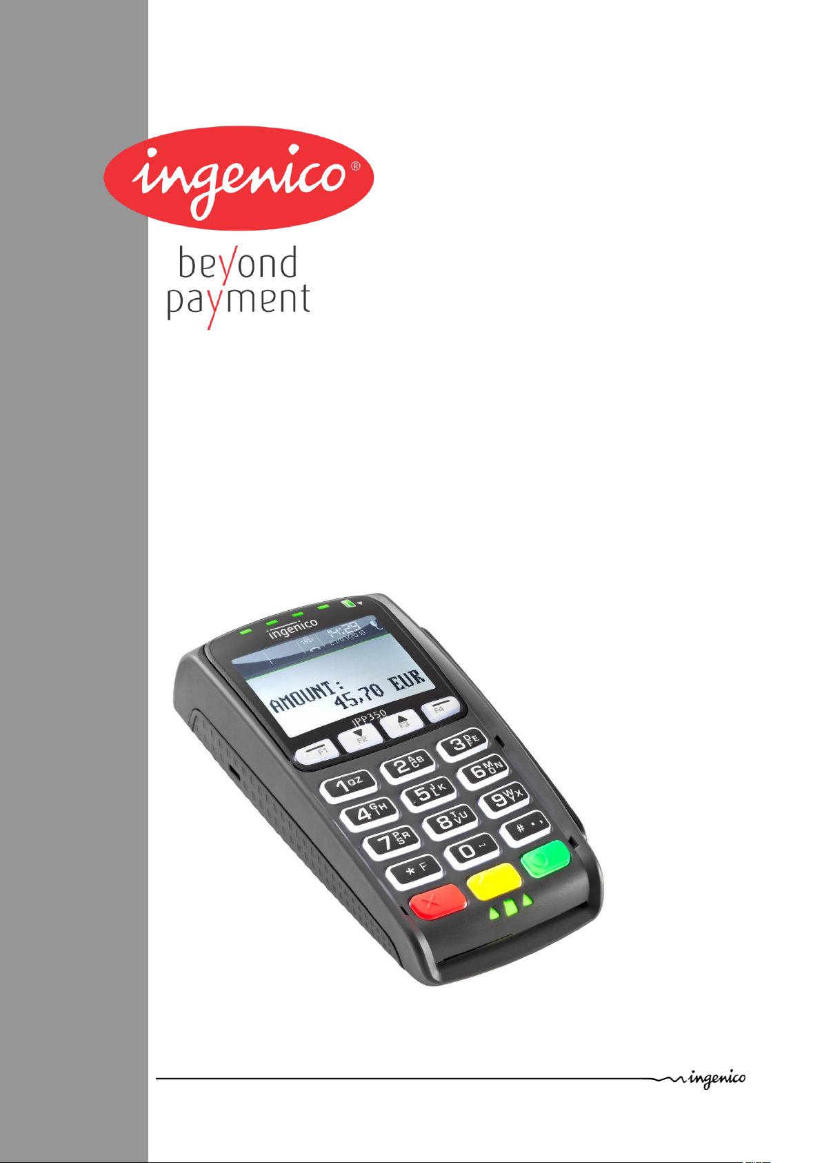
U s e r G u i d e
Product name: IPP3x0-X1Txxxxx
Ingenico – 28/32 Boulevard de Grenelle – 75015 Paris - FRANCE
Tél. 33(0)1 58 01 80 00 - Fax 33 (0)1 58 01 91 35
www.ingenico.com

Contents
1. Introduction __________________________________________________ 4
2. Unpacking ___________________________________________________ 5
3. Recommendations _____________________________________________ 5
3.1. Security _____________________________________________________________ 5
3.2. Security of your terminal _______________________________________________ 6
3.3. IPP3xx Fixed Installation ________________________________________________ 6
3.4. EC standard compliance marking _________________________________________ 8
3.5. IC statements ________________________________________________________ 8
3.6. FCC Statement ________________________________________________________ 8
3.7. Main Characteristics ___________________________________________________ 9
4. Installation and connection _____________________________________ 10
4.1. Positioning the terminal _______________________________________________ 10
4.2. Connections _________________________________________________________ 10
4.2.1. Cable or adaptor connection ____________________________________________________ 10
4.2.2. Cable or adaptor disconnection ___________________________________________________ 11
4.2.3. Installation of the Magic Box (optional) ____________________________________________ 12
12
4.3. Installing SAM (Secure access module) and MicroSD Card ___________________ 13
4.4. ___________________________________________________________________ 14
5. Daily use _____________________________________________________ 15
5.1. Keypad functions ____________________________________________________ 15
5.2. Adjusting the contrast ________________________________________________ 15
5.3. Card insertion _______________________________________________________ 16
5.3.1. Swiping a card ________________________________________________________________ 16
5.3.2. Inserting a chip card ___________________________________________________________ 16
5.3.3. Reading Contactless (Optional) __________________________________________________ 16
6. Maintenance _________________________________________________ 17
Product name: IPP3x0-X1Txxxxx 2/20 Copyright © 2012 Ingenico
900001663 R11 000 08/1227 All rights reserved

Cleaning of the terminal ___________________________________________________ 17
6.1. Transport and storage ________________________________________________ 17
6.2. Troubleshooting _____________________________________________________ 17
6.3. End of life ___________________________________________________________ 18
6.3.1. End of live ___________________________________________________________________ 18
6.3.2. Product end of life disassembly instructions ________________________________________ 18
Product name: IPP3x0-X1Txxxxx 3/20 Copyright © 2012 Ingenico
900001663 R11 000 08/1227 All rights reserved
1. Introduction
Thank you for choosing a payment terminal from Ingenico.
We recommend that you to read this installation guide carefully: It gives you the necessary
information about safety precautions, unpacking, installation, and maintenance of your
terminal.
WARRANTY / SECURITY
To benefit from the product warranty, and to respect the security of the product, we ask
you to use only the accessories delivered in the box with the product, and to ensure
maintenance operations are only performed by an authorized person.
GARANTIE / SICHERHEIT
Um das mit der Garantie verbundene Erzeugnis nutzen und die Sicherheit wahren zu
können, bitten wir Sie, nur die mit dem Erzeugnis in der Verpackung gelieferten
Zubehörteile zu verwenden und die Wartungsarbeiten einer dazu berechtigten Person
anzuvertrauen.
The IPP3X0-X1TXXXXX can be powered by different sources please respect these
recommendations:
All external circuits connected to the IPP3X0-X1TXXXXX must be SELV (Safety Extra Low
Voltage) and LPS (limited power source) within the meaning of section 2.2 and 2.5 of the
standard IEC60950-1:2005+/A1:2010 and EN60950-1:2006+/A11:2009+/A1:2010+/A12:2011
IPP3X0-X1TXXXXX can be USB powered from a USB port; it must be connected to a fully
compatible USB port.
USB 5V 500 mA
IPP3X0-X1TXXXXX can be powered from an Power Over Ethernet (POE) port; it must be
connected to a full compatible POE port.
POE 48V (1.3W)
When IPP3X0-X1TXXXXX is driven by RS232 interface, it must be powered by the specific
power supply supplied by Ingenico.
Falls IPP3X0-X1TXXXXX durch RS232 betrieben wird, muss die von Ingenico bereitgestellte
spezifische Stromversorgung verwendet werden.
For Europe use power supply 152810 and PSC16E-080, l’USB et le POE
For US and Canada use supply 153051, l’USB et le POE
The PSU is 8-12 volts DC and must be compliant with international standard IEC60950-1 (§2.5
: limited power source)
8 – 12 V 450 mA
Note :
Failure to comply with these instructions will void the manufacturer’s responsibility.
This symbol indicates an important Warning.
Dieses Symbol stellt ein wichtiges Warnzeichen dar.
This symbol indicates a piece of advice.
Product name: IPP3x0-X1Txxxxx 4/20 Copyright © 2012 Ingenico
900001663 R11 000 08/1227 All rights reserved
2. Unpacking
ADVICE
Carefully preserve the packaging of the IPP3X0-X1TXXXXX. It must be re-used whenever the
terminal is shipped.
According to the model, the following items are included in the IPP3X0-X1TXXXXX box
(including optional accessories):
The IPP3X0-X1TXXXXX terminal
This installation guide
The IPP3X0 cradle (optional)
The connection cable or adaptor (optional)
The application user guide (optional)
3. Recommendations
3.1. Security
Power on/Power down
To power on or power off the IPP3X0-X1TXXXXX you must connect or disconnect the cable
connected to the host port (for USB or Power Over Ethernet)
If the serial link is used with an additional power supply:
The disconnection device of the terminal is the separable plug of the power supply cord.
Therefore the socket outlet must be installed close to the equipment and shall be easily
accessible by the operator.
Zum Ein- oder Ausschalten des IPP3X0-X1TXXXXX wird das mit dem Host (für USB oder
Power Over Ethernet) verbundene Kabel eingesteckt oder abgeklemmt.
Falls die serielle Verbindung mit zusätzlicher Stromversorgung genutzt wird:
Die Abschaltvorrichtung des Geräts besteht aus dem abtrennbaren Stecker des
Stromkabels.
Dementsprechend muss die Steckdose in der Nähe des Geräts angebracht werden und für
den Benutzer leicht zugänglich sein.
Lithium battery
The IPP3X0-X1TXXXXX is fitted with a lithium battery which is not accessible to the user.
Only a qualified technician may be authorized to open the unit and change this component.
For Switzerland annex 2.15 of SR 814.81 applies for batteries.
SAM, MMC and contactless lid
The lid located under the terminal (see chapter “Installation SAM”) must be in place during
normal operation of the terminal.
Product name: IPP3x0-X1Txxxxx 5/20 Copyright © 2012 Ingenico
900001663 R11 000 08/1227 All rights reserved
3.2. Security of your terminal
DC Power jack polarity
Upon receipt of your terminal you should check for signs of tampering of the terminal. It is
strongly advised that these checks are performed regularly on the terminal. You should
check, for example: that the keypad is firmly in place; that there is no evidence of unusual
wires that have been connected to any ports on your terminal or associated equipment, the
chip card reader, or any other part of your terminal. Such checks would detect any
unauthorised modifications to your terminal, and other suspicious behaviour of individuals
that have access to your terminal. Your terminal detects any “tampered state”. In this state
the terminal will repeatedly flash the message” Alert Irruption!” and further use of the
terminal will not be possible. If you observe the “Alert Irruption!” message, you should
contact the terminal helpdesk immediately.
You are strongly advised to ensure that privileged access to your terminal is only granted to
staff that have been independently verified as being trustworthy.
CAUTION
NEVER ask the customer to divulge their PIN Code. Customers should be advised to ensure
that they are not being overlooked when entering their PIN Code.
3.1. Marking
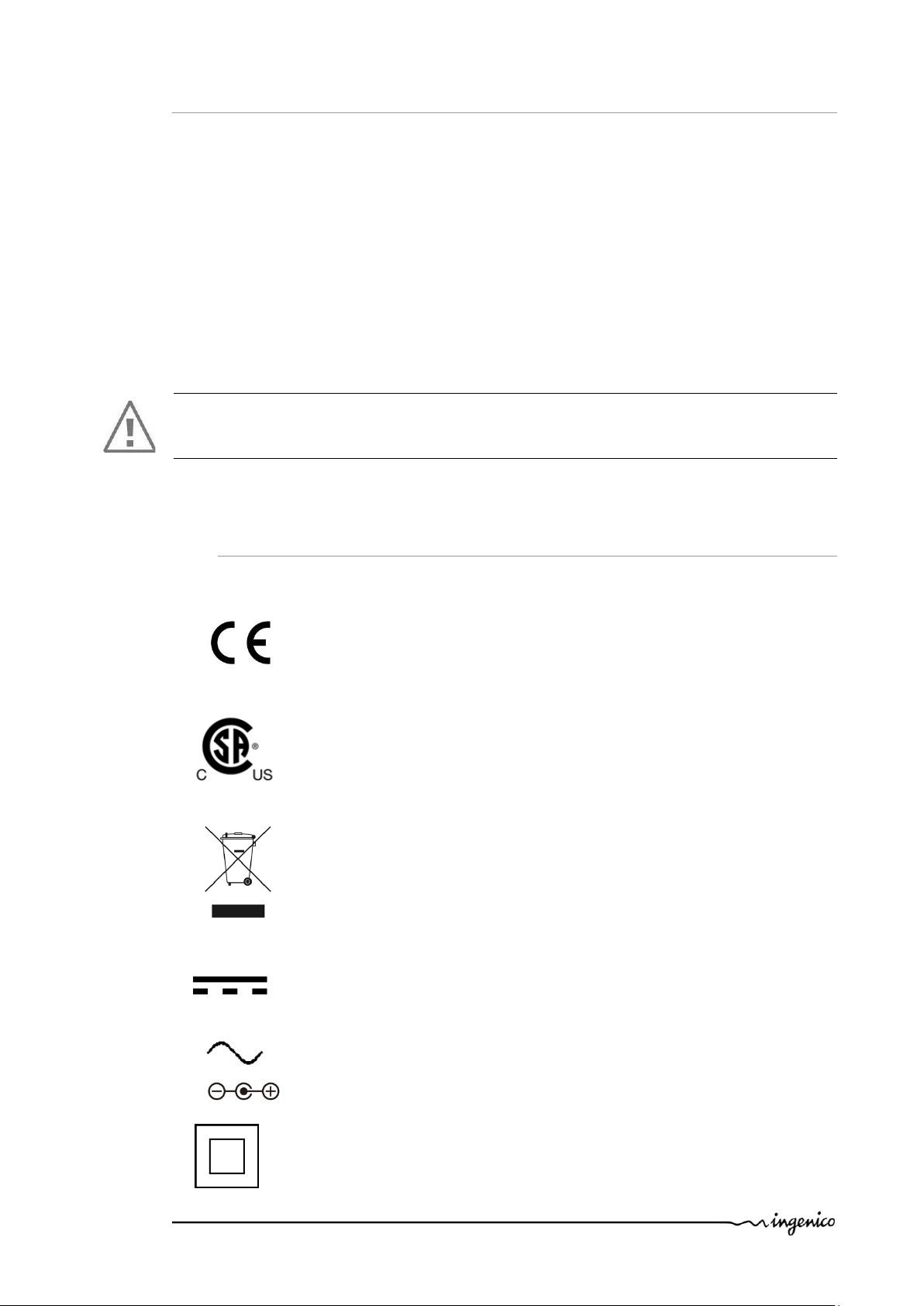
Below, you will find the different symbols used on the product and its power supply.
The CE marking is the manufacturer's declaration that the product meets
the requirements of the applicable EC directives. The CE mark is a
mandatory conformity marking for certain products sold within the
European Economic Area (EEA).
The CSA mark shows that your products have been certified by an
accredited third party lab and have met applicable standards as required by
North American law.
Waste of Electrical and Electronic Equipment (WEEE) symbol indicates that
when the end-user wishes to discard this product, it must be sent to
separate collection facilities for recovery and recycling. By separating this
product from other household-type waste, the volume of waste sent to
incinerators or land-fills will be reduced and natural resources will thus be
conserved.
This logo indicates that the product operates with a continuous voltage. This
symbol is followed by the ratings (voltage and current for instance)
This logo indicates that the product operates with an alternative voltage.
This symbol is followed by the ratings (voltage and current for instance)
Double insulated or class 2 electrical appliances are products that have been
designed in a way so as not to require a safety connection to electrical earth
(These products must NOT have a safety connection to Earth).
Product name: IPP3x0-X1Txxxxx 6/20 Copyright © 2012 Ingenico
900001663 R11 000 08/1227 All rights reserved

Indoor use symbol.
Limited Power Supply
3.2. IPP3xx Fixed Installation
If the device is to be used in a situation where it is not possible for the cardholder to pick up
and shield their PIN entry themselves,
the device may be used without PIN shield, but it must be installed in the following manner:
a) The device must be angled at 45 or more, so that oversight of the PIN entry from the rear
of the device is not possible.
b) The device must either be fitted in a swivel stand – so that the customer can position the
device in the best angle to prevent oversight – or the device must be fixed in the best
possible position to prevent oversight if such a generic position exists in the specific
environment to which the device is installed.
c) The device environment must be accompanied with conspicuous notices and educational
material which informs the customer to shield their PIN during PIN entry.
d) The device must be deployed so that oversight from other customers, either in different
payment lanes, or in other areas of the shopping environment, is prevented. This may be
achieved through the placement of the lanes and device , so that the customer is
automatically positioned between the device keypad and other customers. Alternatively, it
may be achieved by the environment in which the device is installed, so that the checkout
itself shields the PIN entry process.
e) The terminal is exclusively made for indoor use
Product name: IPP3x0-X1Txxxxx 7/20 Copyright © 2012 Ingenico
900001663 R11 000 08/1227 All rights reserved

3.3. EC standard compliance marking
EC standard compliance marking certifies that the product stipulated below:
IPP3X0-X1TXXXXX
conforms to the following harmonized standards :
– IEC/EN 60950-1: Electrical safety of data processing equipment including electrical
office equipment. Issue dec. 2001
EN 55022: Data processing equipment – Radiofrequency disturbance characteristics Limits and measurement methods. EN 55022 2006 + A1 (2007)
– EN 55024: Data processing equipment – Immunity characteristics - Limits and
measurement methods. Issue 1998 + A1- 2001 + A2 – 2003
3.4. IC statements
Under Industry Canada regulations, this radio transmitter may only operate using an
antenna of a type and maximum (or lesser) gain approved for the transmitter by Industry
Canada. To reduce potential radio interference to other users, the antenna type and its gain
should be so chosen that the equivalent isotropically radiated power (e.i.r.p.) is not more
than that necessary for successful
communication."
Conformément à la réglementation d'Industrie Canada, le présent émetteur radio peut
fonctionner avec une antenne d'un type et d'un gain maximal (ou inférieur) approuvé pour
l'émetteur par Industrie Canada. Dans le but de réduire les risques de brouillage
radioélectrique à l'intention des autres utilisateurs, il faut choisir le type d'antenne et son
gain de sorte que la puissance isotrope rayonnée équivalente (p.i.r.e.) ne dépasse pas
l'intensité nécessaire à l'établissement d'une communication satisfaisante.
"This device complies with Industry Canada licence-exempt RSS standard(s). Operation is
subject to the following two conditions: (1) this device may not cause interference, and (2)
this device must accept any interference, including interference that may cause undesired
operation of the device."
“Le présent appareil est conforme aux CNR d'Industrie Canada applicables aux appareils
radio exempts de licence. L'exploitation est autorisée aux deux conditions suivantes : (1)
l'appareil ne doit pas produire de brouillage, et (2) l'utilisateur de l'appareil doit accepter
tout brouillage radioélectrique subi, même si le brouillage est susceptible d'en
compromettre le fonctionnement ”.
3.5. FCC Statement
FCC standard compliance marking certifies that the product stipulated below:
IPP3X0-X1TXXXXX
conforms to the following harmonized standards :
– part 15 subpart B of the FCC rules
This class (B) digital apparatus complies with Canadian ICES-003.
Information to users:
This device complies with FCC and IC radiation exposure limits set forth for general
population. This device must be installed to provide a separation distance of a least 20cm
Product name: IPP3x0-X1Txxxxx 8/20 Copyright © 2012 Ingenico
900001663 R11 000 08/1227 All rights reserved

from all persons and must not be co-located or operating with any other antenna or
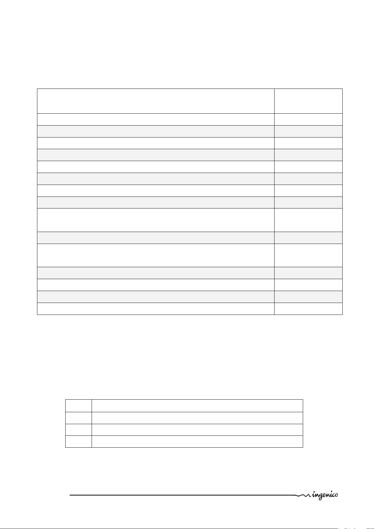
Mass
260 g without cable
Dimensions
169,5 x 83x 42 mm (l x w x h)
Ambient temperature
from +5°C to +40°C
Max relative humidity
85% at +40°C
Link
USB, Power Over Ethernet or RS232 and
power supply
Storage temperature
-20°C,+55°C
Max relative humidity
85% at +55°C
transmitter.
Changes or modifications not expressly approved by the party responsible for compliance
could void the user’s authority to operate the equipment.
NOTE: This equipment has been tested and found to comply with the limits for a Class B
digital device, pursuant to part 15 of the FCC Rules. These limits are designed to provide
reasonable protection against harmful interference in a residential installation. This
equipment generates uses and can radiate radio frequency energy and, if not installed and
used in accordance with the instruction, may cause harmful interference to radio
communications. However, there is no guarantee that interference will not occur in a
particular installation. If this equipment does cause harmful interference to radio or
television reception which can be determined by turning the equipment off and on, the
user is encouraged to try to correct interference by one or more of the following measures:
- Reorient or relocate the receiving antenna.
- Increase the separation between the equipment and receiver.
- Connect the equipment into an outlet on circuit different from that to which the receiver
is connected.
- Consult the dealer or an experienced radio/TV technician for help.
3.6. Main Characteristics
The main technical characteristics of the terminal Ingenico IPP3X0-X1TXXXXX are:
Operating conditions
Storage conditions
Product name: IPP3x0-X1Txxxxx 9/20 Copyright © 2012 Ingenico
900001663 R11 000 08/1227 All rights reserved

4. Installation and connection
4.1. Positioning the terminal
Install the terminal on a flat surface, with an easy access to an electrical outlet. Place the
terminal away from any heat source and protected from dust, vibrations and electromagnetic
radiations (away from video terminals, PC, anti-shoplifting barriers, ...).
Terminal Location
The positioning of the IPP3xx on a counter stand must be in such a way to make cardholder
PIN (Personal Identification Number) spying infeasible.
Avoid exposing the terminal to the direct rays of the sun.
4.2. Connections
A connection area is located on the rear of the terminal.
In this place it’s possible to plug one of the different specific cables, or an adaptor to
replace directly another product on the field.
In this last case, the specific adaptor must be chosen in the Ingenico range.
4.2.1. Cable or adaptor connection
Present the device in front of the connector and plug it
Product name: IPP3x0-X1Txxxxx 10/20 Copyright © 2012 Ingenico
900001663 R11 000 08/1227 All rights reserved

Cables and accessory are able to be fixed with two braces and two M2.5x8 screws (Kit
296133808 not included in the package)
CAUTION
Use only an Ingenico cable or accessory so as not to void the warranty.
WARNUNG
Verwenden Sie nur das von Ingenico bereitgestellte Kabel oder Zubehör, um die Garantie
nicht aufzuheben.
4.2.2. Cable or adaptor disconnection
On specific cables, a handle helps the disconnection
Product name: IPP3x0-X1Txxxxx 11/20 Copyright © 2012 Ingenico
900001663 R11 000 08/1227 All rights reserved

4.2.3. Installation of the Magic Box (optional)
1 3 2
ADVICE
It is strongly recommended to attach the “Magic cable” to the terminal’s work area in
order to reduce stress on the terminal and connection.
Examples of securing the “Magic Cable” are as illustrated:
1. Using the supplied cable tie to attach to a table leg (or similar)
2. Using the supplied cable tie and self-adhesive support
3. Using a counter-sunk screw (not supplied) to an appropriate surface
The “Magic Cable” should be readily accessible for support and terminal helpdesk
diagnosis purposes.
Note: The connection Magic Box can also be attached using a VELCRO™ or other system.
CAUTION
Plug Ethernet cable before power supply
Use POE (Power over Ethernet) without power supply for 296120447 and 296121027 cables.
Product name: IPP3x0-X1Txxxxx 12/20 Copyright © 2012 Ingenico
900001663 R11 000 08/1227 All rights reserved

4.3. Installing SAM (Secure access module) and MicroSD Card
SAM
Cut corner
Adhesive
CAUTION :
Before starting, switch off the terminal by disconnecting the power supply or the link to the
host
WARNUNG:
Vor Beginn sollte das Endgerät ausgeschaltet werden, indem die Stromversorgung oder die
Verbindung zum Host abgeschaltet wird
In order to access the SAM card you must first remove the SAM compartment cover located
at the back of your terminal.
Press the two clips of the cover and open the cover.
Insert completely the MicroSD Card into the slot marked (MicroSD) as indicated on
the figure.
Take care to ensure that the MicroSD Card is inserted in the correct manner.
Insert the SAM Card into the slot marked (1),(2) or (3). Take care to ensure that the
SAM Card is inserted in the correct manner. The cut corner must be positioned as
indicated on the figure.
To remove the SAM card, Ingenico recommend that you to use a piece of adhesive
tape previously applied on both sides of the SAM as shown here below
CAUTION:
Do not use any tools when installing or removing the SAM Card.
WARNUNG:
Verwenden Sie keinerlei Werkzeug für den Einsatz oder das Entfernen der SAM-Karte.
Product name: IPP3x0-X1Txxxxx 13/20 Copyright © 2012 Ingenico
900001663 R11 000 08/1227 All rights reserved

Replace the cover as illustrated by the procedure below:
The SAM door is able to be fixed with one M2.5x8 screw (not included
in the package)
Product name: IPP3x0-X1Txxxxx 14/20 Copyright © 2012 Ingenico
900001663 R11 000 08/1227 All rights reserved

5. Daily use
1 4 2 3 5
5.1. Keypad functions
1. NAVIGATION keys in the menus – Interactive keys for use between the screen
2. CANCEL key (red)
3. CLEAR key (yellow)
4. VALIDATION key (green)
5. Dot Key
5.2. Adjusting the contrast
There is no contrast management for the Colour display
The screen of your chart is 128 x 64 pixels, illuminated with white light.
If you wish to increase or to decrease the contrast of the characters displayed on screen,
press simultaneously on the (dot key) and key in order to decrease the
contrast, or the (dot key) and key in order to increase.
Keep pressing the keys as long as necessary.
Product name: IPP3x0-X1Txxxxx 15/20 Copyright © 2012 Ingenico
900001663 R11 000 08/1227 All rights reserved

5.3. Card insertion
Green
lights
Contactless
Do not insert any foreign object into the slot of the magnetic card reader or smart card
reader.
5.3.1. Swiping a card
Insert the card manually into the reader with the magstripe-
facing towards the keypad.
Swipe the magnetic card at a constant speed, not too slow
and not too fast, to ensure the card is read successfully.
5.3.2. Inserting a chip card
The chip Cards should be inserted into your terminal as illustrated with the chip
facing up and into the card reader
5.3.3. Reading Contactless (Optional)
Bring the card firmly up to the active zone above the display (at about 1cm). Keep
the card close to the display during the transaction
Your contactless terminal has a row of four status lights that are visible on display.
When a contactless transaction is started the first (left hand) status light will be lit
steadily; this indicates that the contactless display is in use but a card is not being
read.
When a contactless card is presented to the contactless active zone during a
transaction the second, third and fourth status lights will be lit in turn. The card
read is successful when all four status lights are lit and the confirmation tone is
heard.
Active Zone
Product name: IPP3x0-X1Txxxxx 16/20 Copyright © 2012 Ingenico
900001663 R11 000 08/1227 All rights reserved

6. Maintenance
ATTENTION
Before making any maintenance operations on the terminal, make sure that the power
supply is disconnected.
WARNUNG
Stellen Sie vor der Durchführung von Wartungsarbeiten am Endgerät sicher, dass die
Stromversorgung ausgeschaltet ist.
Cleaning of the terminal
First of all, unplug all the cables from the terminal.
Good rules for proper cleaning of the terminal are:
Use a damp soft cloth to clean the outside of the terminal. Or alternatively a
terminal wipe supplied by Ingenico.
Do not clean the electrical connections.
Do not use in any case, solvents, detergents or abrasive products:
Those materials might damage the plastic or electrical contacts.
Do not insert any foreign objects into the slot of the smart card reader
The card readers can be cleaned using Ingenico supplied cleaning cards.
Avoid exposing the terminal to the direct rays of the sun.
6.1. Transport and storage
Use the original packaging for any unit or stored.
Disconnect all cables from the terminal during the transport.
6.2. Troubleshooting
Cards are not read
Check that the magnetic card is passed correctly (with magnetic band
directed to the interior of the terminal)
Swipe again the card with the magnetic stripe movement constant and rapid
Verify that the magnetic strip is not damaged, grooved or cracked
Make sure you have inserted correctly the smart card into the smart card reader
and removed the card only after the transaction
Product name: IPP3x0-X1Txxxxx 17/20 Copyright © 2012 Ingenico
900001663 R11 000 08/1227 All rights reserved

6.3. End of life
Product Name
Nom du produit
Product description
Description du produit
Product mass (g)
Masse du produit (g)
IPP320
electronic payment pinpad
280
IPP350
electronic payment pinpad
280
6.3.1. End of live
This product is labeled in accordance with European Directives 2002/96/EC concerning
Waste Electrical and Electronic Equipment (WEEE) and 2006/66/EC concerning Batteries
and Accumulators. Those provisions are requiring producers and manufacturers to become
liable for take-back, treatment and recycling upon end of life of equipment and batteries.
The associated symbol means that WEEE and waste batteries must not be thrown
away but collected separately and recycled.
Ingenico ensures that efficient collection and recycling schemes are set-up for WEEE
and batteries according to the local regulation of your country. Please contact your
retailers for more detailed information about the compliance solution in place for disposing
of your old product and used batteries.
Packaging waste must also be collected separately to assure a proper disposal and
recycling.
Please note that proper recycling of the electrical and electronic equipment and waste
batteries will ensure safety of human health and environment.
6.3.2. Product end of life disassembly instructions
This document is intended for treatment and recycling facilities. It provides the basic
instructions for the disassembly of Ingenico products to remove components and
materials requiring selective treatment, as defined by EU directive 2002/96/EC, Waste
Electrical and Electronic Equipment (WEEE).
Ce document est destiné aux installations de traitement et de recyclage. Il fournit les instructions de base
pour le démontage de produits Ingenico afin de retirer les composants et matériaux nécessitant un
traitement sélectif, tel que défini par la directive européenne 2002/96/CE, sur les Déchets d’Equipements
Electriques et Electroniques (DEEE).
MODELS AND DESCRIPTIONS
MODELES ET DESCRIPTIONS
Products covered by these disassembly instructions.
Produits concernés par ces instructions de démontage.
Product name: IPP3x0-X1Txxxxx 18/20 Copyright © 2012 Ingenico
900001663 R11 000 08/1227 All rights reserved
COMPONENTS AND MATERIALS REQUIRING SELECTIVE TREATMENT
Components and materials
Composants et matériaux
Quantity included in
product(s)
Quantité contenue
dans le(s) produit(s)
Capacitors containing Polychlorinated biphenyls (PCB)
Condensateurs contenant du polychlorobiphényle (PCB)
0
Components containing Mercury, such as switches or backlighting lamps
Composants contenant du mercure, tels que les interrupteurs ou les lampes à rétroéclairage
0
Batteries
Piles et accumulateurs
1
Printed circuit boards greater than 10 cm²
Cartes de circuits imprimés de plus de 10 cm²
2
Toner cartridges
Cartouches de toner
0
Plastic containing brominated flame retardants
Matières plastiques contenant des retardateurs de flamme bromés
0
Asbestos waste and components which contain asbestos
Déchets d'amiante et composants contenant de l'amiante
0
Cathode ray tubes
Tubes cathodiques
0
Chlorofluorocarbons (CFC), Hydrochlorofluorocarbons (HCFC) or Hydrofluorocarbons
(HFC), Hydrocarbons (HC)
Chlorofluorocarbones (CFC), hydrochlorofluorocarbone (HCFC) ou hydrofluorocarbone (HFC),
hydrocarbures (HC)
0
Gas discharge lamps
Lampes à décharge
0
Liquid crystal displays (LCD) of a surface greater than 100 cm² and all those back-lighted with
gas discharge lamps
Écrans à cristaux liquides (LCD) d'une surface supérieure à 100 cm² et tous les écrans rétroéclairés par
des lampes à décharge
0
External electric cables
Câbles électriques extérieurs
0
Components containing refractory ceramic fibres
Composants contenant des fibres céramiques réfractaires
0
Components containing radioactive substances
Composants contenant des substances radioactives
0
Electrolyte capacitors measuring greater 2,5 cm in diameter or height
Condensateurs électrolytiques mesurant plus de 2,5 cm de diamètre ou de hauteur
0
Step
Etape
Product disassembly process
Processus de démontage du produit
1
Unclip the back door and unplug the printed circuit.
Déclipser la trappe arrière et débranché le circuit imprimé.
2
Unscrew the six screws and disassemble the bottom casing.
Dévisser les six vis et démonter le capot arrière.
3
Disassemble the large printed circuit, unclip the display and the ISO head reader.
Démonter le grand circuit imprimé, déclipser l’afficheur et la tête de lecture magnétique.
COMPOSANTS ET MATERIAUX NECESSITANT UN TRAITEMENT SELECTIF
The following components and materials, if present in the Ingenico product(s), have to be
removed and selectively treated.
Les composants et matériaux suivants, si présents dans le(s) produit(s) Ingenico, doivent être retirés et
faire l’objet d’un traitement sélectif.
PRODUCT DISASSEMBLY PROCESS
PROCESSUS DE DEMONTAGE DU PRODUIT
Basic steps to remove components and materials previously identified and requiring
selective treatment.
Etapes de base pour retirer les composants et matériaux précédemment identifiés et nécessitant un
traitement sélectif.
Product name: IPP3x0-X1Txxxxx 19/20 Copyright © 2012 Ingenico
900001663 R11 000 08/1227 All rights reserved

Ingenico
28/32 Boulevard de Grenelle
75015 Paris - France
Tél.: + 33 1 58 01 80 00 - Fax: + 33 1 58 01 91 35
www.ingenico.com
Ingenico
192 avenue Charles de Gaulle
92200 Neuilly sur Seine - France
Tél.: + 33 1 46 25 82 00 - Fax: + 33 1 47 72 56 95
www.ingenico.com
Your contact
“This Document is Copyright © 2012 by INGENICO Group. INGENICO retains full copyright ownership,
rights and protection in all material contained in this document. The recipient can receive this
document on the condition that he will keep the document confidential and will not use its contents
in any form or by any means, except as agreed beforehand, without the prior written permission of
INGENICO. Moreover, nobody is authorized to place this document at the disposal of any third party
without the prior written permission of INGENICO. If such permission is granted, it will be subject to
the condition that the recipient ensures that any other recipient of this document, or information
contained therein, is held responsible to INGENICO for the confidentiality of that information.
Care has been taken to ensure that the content of this document is as accurate as
possible. INGENICO however declines any responsibility for inaccurate, incomplete or outdated
information. The contents of this document may change from time to time without prior notice, and
do not create, specify, modify or replace any new or prior contractual obligations agreed upon in
writing between INGENICO and the user.
INGENICO is not responsible for any use of this device, which would be non consistent with the
present document.
All trademarks used in this document remain the property of their rightful owners.”
Product name: IPP3x0-X1Txxxxx 20/20 Copyright © 2012 Ingenico
900001663 R11 000 08/1227 All rights reserved
 Loading...