

Page 1

Installation Guide
LP 740 Series
Ceiling Mount
Installation Guide
LP 740 Series
Installationhandbuch zur
Deckenbefestigung
English. . . . . . . . . . . . .1
Deutsch . . . . . . . . . .13
Page 2

Copyright © 1998 by In Focus, Inc.
W ilsonville , Oregon. All rights res erved.
Copyright © 1998 by In Focus, Inc.
Wilsonville, Oregon, USA. Alle Rechte vorbehalten.
010-0170-00
Page 3

CEILING MOUNT INSTALLATION GUIDE
TM
The LP 740 LiteMount
makes it easy to hang
your projector from the ceiling for fixed installation use in meeting, auditorium and training
room settings.
You must determine the suitability of this product for your intended use and assume all risk
and liability in connection therewith. In Focus
recommends that a professional contractor or
other facilities professional assist you in mounting this device. Be sure to take precautions to
meet all local building codes.
WARNING:
tion must be performed in
compliance with your local
building code requirements. Local require-
This installa-
Additional LiteMount Products
In Focus offers two additional LiteMount products that may make your ceiling mount installation easier.
•
The LiteMount False Ceiling Plate
SP-LTMT-PLT
(
) is designed for suspended ceilings wit h aco ust ic ti le s. It moun ts in you r c ei ling in place of a ceiling tile. It is preassembled with threaded studs to instal l the
LiteMount brackets, and includes the necessary hardware to attach to the brackets.
•
The LiteMount Pipe Tubing Extension (
LTMT-EXT
) allows you to install the projector
SP-
in a room with a high ceiling. With the extension, you can place the projector from 24”
(61 cm) to 46” (117 cm) from the ceiling (12”
to 24” with cut).
ments take precedence
over any instructions given
in this guide.
Contact your In Focus dealer to or der these pr o ducts.
Placing the Projector
Refer to the
LP 740 User’s Guide
tances and sizes to determine where to install the
ceiling mount to meet your projection needs.
for image dis-
1
Page 4

Contents
Contents
The LP 740 Ceiling Mount package contains:
Installation Guide
1
NOTE
load the ceiling mount can
: The maximum
support is 50 pounds .
ceiling mount base box
2
dimensions: 11.6” x 10” x 1.5”
weight: 4.2 lbs
projector mounting bracket
3
dimensions: 12” x 7.8” x 1.5”
weight: 2.2 lbs
hardware for installing the projector mount-
4
ing bracket on the projector:
•
three (3) 5 mm Phillips-head screws
•
three (3) 5 mm quick release sleeves
•
one (1) 5 mm knurled knob screw
hardware for installing the projector (with
5
mounting plate) to the base box in the ceiling:
•
four (4) 6mm kn urled knob screws
•
two (2) 6 mm flat washers
•
two (2) 6 mm conical spacers
2
Page 5

Install the C eilin g Mount Base Bo x o n the Ceil ing
Instructions for installing the ceiling mount on
the LiteMount False Ceiling Plate an d the LiteMount Pipe Tubing Extension are given in this
installation guide. If you have not purchased
either of these products, consult a professional
contractor or other facilities professional to
ensure a safe installation.
WARNING
structure must be able to
support at least 5 times
the weight of the pro jector
and mounting hardware. If
: The ceiling
Please refer to the LiteMount False Ceiling Plate
and LiteMount Pipe Tubing Exten sion installation instructions for lists of included hardware.
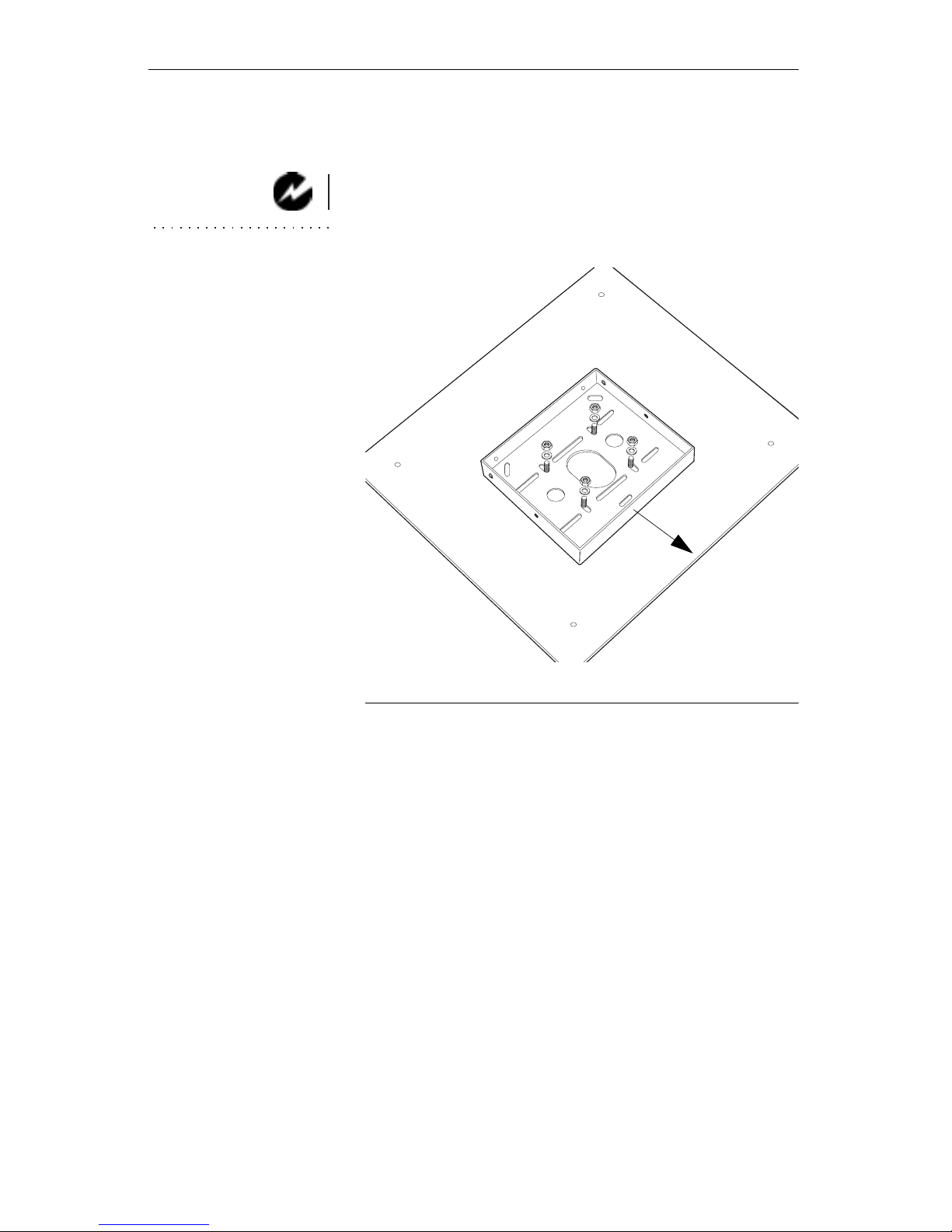
Center the ceiling mount base box on the ceil-
1
ing plate as shown in Figure 1. Make sure the
front of the base box faces forward toward
your projection screen. The front side of the
base box is the only surface without drilled
holes.
LiteMount False Ceiling Plate - Align the
2a
holes in the base box with the threaded studs
on the plate. Install the 4 washers and nuts as
shown in Figure 1.
LiteMount Pipe Tubing Extension - Line up
2b
the holes in the base box with the holes in the
plate at the end of the pipe extension. Install
the hardware as shown in Figure 2.
not, it must be reinforced
according to your local
building codes.
NOTE
Installation Instructions
that came with the Lite-
: Refer to the
Mount False Ceiling Plate
and the LiteMount Pipe
Tubing Extension for
important additional information.
3
Page 6
Install the Ceiling Mount Base Box on the Ceiling
Place the ceiling plate or pipe extension in the
3
ceiling so that the base box hangs down into
the room.
Route the projector’s cables through your
4
ceiling and out the hole in the ceilin g.
WARNING
: If the
dropped ceiling is an air-
handling plenum, be sure
the cables are plenum-
rated, or install the cables
within conduit.
F
IGURE
make sur e this
surface faces front
1
Install the base box to the LiteMount False Ceiling Plate
4
Page 7

false ceiling plate
make sur e this
surface fa ces front
F
IGURE
2
Install the base box to the LiteMount Pipe Tubing Extension
5
Page 8
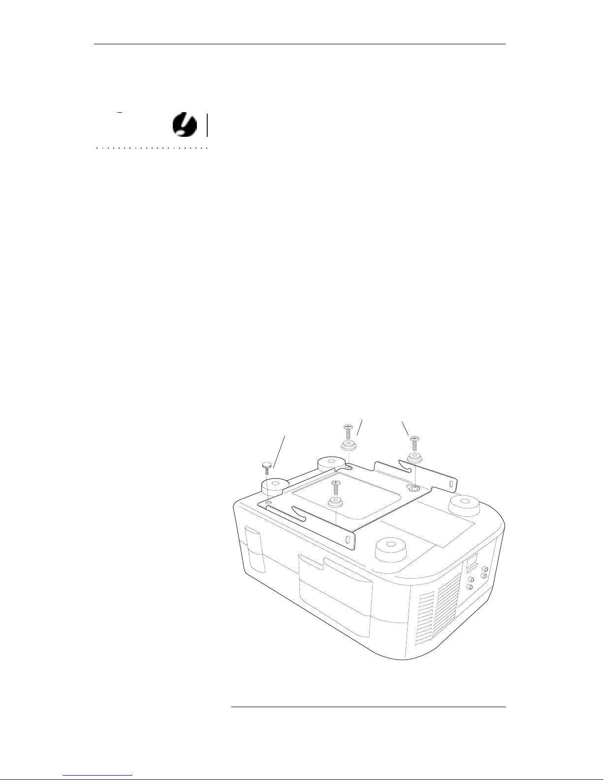
Attach the Mounting Plate to the Projector
Attach the Mounting Plate to the Projector
Set the projector on a table with the bottom
1
side up. Align the holes in the mounting plate
with the holes in the projector.
Insert the 3 screws into the 3 quick release
2
CAUTION
: Use only the
sleeves (Figure 3).
hardware that is provided
with the LP 740 Ceiling
Mount. Using different
hardware may damage
your projector.
Loosely attach the screws and sleeves to the
3
holes in the projector as shown in Figure 3.
Align the keyholes in the mount ing bracket
4
with the screws in the projector. Slide the
mounting bracket until the quick release
sleeves are at the top of the keyhole slot.
Attach the 5mm knurled knob to the projector
5
in the location shown in Figure 3. Tighten the
three 5mm screws and the 5 mm knurled
knob. Be careful not to over-tighten the
screws.
knurled knob
goes here
quick release screws
6
F
IGURE
Attach the mounting plate to the projector
3
Page 9

Hang the Projector on the Ceiling
Loosely install the 6 mm knurled knobs, flat
1
washers, and conical spacers to the 2 hinge
pins on the base box (Figure 4).
spacer
washer
knurled knob
slide projector
bracket here between
the base box and the spacer
F
IGURE
Attach knurled knobs to the side of the base box
Make sure your cables are pulled thr ough the
2
center hole of the base box, then carefully lift
the projector and turn it upside down so the
mounting plate faces the ceili ng (Figure 5).
Insert the projector and mounting bracket
3
slots onto the base box hinge pins between
the spacers and base box (Figure 4). Slide the
projector bracket forward until the hinge pins
rest fully in the vertical slots and support the
projector.
4
7
Page 10

Hang the Projector on the Ceiling
F
IGURE
5
Install the projector in the ceiling base box
Insert the remaining two 6 mm knurled
4
knobs through the rear slots in the mounting
bracket and into the holes on the sides of the
base box.
Insert knurled knob
through this slot
8
F
IGURE
6
Insert the knurled knobs to adjust the angle
Page 11

Adjust the angle of the projector so th at it will
5
project correctly. Refer to your
Guide
for detailed information on projection
LP 740 User’s
angles and image sizes.
Tighten all the knurled knobs to secure the
6
projector in position.
Check all fasteners to make sure they are
7
properly tightened.
Connect the power cord and the cables to the
8
projector. (Refer to your
LP 740 User’s Guide
for information about connecting the cables.)
9
Page 12

Inverting the Image
When you need to remov e the projector or replace
the lamp or clean the air filter:
Disconnect all cables.
1
Hold the projector from underneath.
2
Remove the knurled knob that holds the pro-
3
jector to the mounting plate.
Slide the projector to release it from the quick
4
release bolts. The projector will come off of
the mounting plate. The mount ing plate will
still be attached to the base box.
Replace the lamp or clean the air filter as
5
described in your
LP 740 User’s Guide
if
needed.
Realign the quick release bolts in the keyhole
6
slots on the mounting plate.
7
ADJUSTING THE IMAGE
Inverting the Image
1
2
3
Fasten the knurled knob.
Press the
Menu
button on the remote or keypad to display the projector’s on- screen
menu.
Using the arrow buttons, move the cursor to
the Custom Setup menu, then press
Enter
.
Move the cursor to the Image Mode menu
and press
. Move the cursor to Ceiling,
Enter
then select ON.
10
Page 13

Limited Warranty
In Focus Inc. warrants that each “ceiling mount” sold hereunder will
conform to and function in accordance with the written specifications
of In Focus. Said limited warranty shall apply only to the first person
or entity that purchases the Product for personal or business use and
not for the purpose of distribution or resale. The pr od uct may contain
recycled components that are in new condition. Said warranty shall
continue for a period of one (1) year from the date of such purchase.
In Focus does
Proof of purchase is required for all warranty claims.
not warrant that the Product will meet the spe cific r equir ements o f the
first person or entity that purchases the Product for personal or business use. In Focus’ liability for the breach of the foregoing limited warranty is limited to the repair or replacement of the Product or refund
of the purchase price of the Product, at In Focus’ sole option. To exercise the Purchaser’s rights under the foregoing warranty, the Product
must be returned at the Purchaser’s sole cost and expense, to In Focus,
and must be protected by packaging comparable to the original packaging. The Product must be accompanied by a written letter that
includes (i) proof of date of purchase, (ii) the dealer’s name, (iii) the
part number of the accessory item or the projector/panel model number, (iv) your business card information, (v) explanation of how the
item was damaged, and (vi) description of the damage and reason for
the return. Please call In Focus or your dealer for information on
where to send your case. In Focus will repair/replace and return the
case within 10 days of receipt of the item.
Warranty Limitation and Exclusion
In Focus shall have no further obligation under the foregoing limited
warranty if the Product has been damaged due to abuse, misuse,
neglect, accident, unusual physical stress, unauthorized modifications, tampering, alterations, or service other than by In Focus, causes
other than from ordinary use or failure to properly use the Product in
the application for which said Product is intended.
Disclaimer or Unstated Warranties
The warranty printed above is the only warranty applicable to this
purchase. All other warranties, express or implied, including, but not
limited to, the implied warranties of merchantability and fitness for a
particular purpose are disclaimed. Ther e are no warranties that extend
beyond the face hereof and the foregoing warranty shall not be
extended, altered or varied except by written instrument signed by In
Focus.
Limitation of Liability
It is understood and agreed that In Focus’ liability whether in contract, in tort, under any warranty, in negligence or otherwise shall not
exceed the return of the amount of the purchase price paid by purchaser and under no circumstances shall In Focus be liable for special,
indirect or consequential damages or los t pr ofits, los t r evenues, or lost
savings. The price stated for the product is a consideration in limiting
In Focus’ liability. No action, regardless of form, arising out of the
agreement to purchase the product may be brought by purchaser
more than one year after the cause of action has accrued
11
Page 14

INSTALLATIONSANLEITUNG FÜR DIE DECKENBEFESTIGUNG
TM
Mit dem LiteMount
der LP-Serie 740 können
Sie Ihren Projektor mühelos zur permanenten
Verwendung in Besprechungs-, Vortrags- und
Schulungsräumen an der Decke befestigen.
Sie müssen die Eignung dieses Produkts für den
beabsichtigten Verwendungszweck überprüfen
und übernehmen das gesamte Risiko und die
WARNUNG
Installation muß gemäß
: Diese
volle Haftung in Zusammenhang mit diesem
Produkt. In Focus empfiehlt, daß Ihnen ein
Berufshandwerker bei der Befestigung dieses
Geräts behilflich ist. Vergewissern Sie sich, daß
alle örtlich geltenden Bauvorschriften beachtet
den jeweils geltenden Bauvorschriften durchgeführt
werden. Die örtlichen Bauvorschriften haben Vor-
werden.
rang vor den Anleitungen
LiteMount-Zusatzprodukte
In Focus bietet zwei zusätzliche LiteMount-Produkte an, die die Installation der Deckenbefestigung erleichtern.
•
Die LiteMount-Zwischendeckenplatte (
LTMT-PLT
) ist für abgehängte Decken mit
SP-
Schallschutzfliesen vorgesehen. Sie wird an
der Decke anstelle einer Deckenfliese angebracht und verfügt über vorgebohrte Löcher
zur Montage der LiteMount-Halterung.
•
Mit der LiteMount-Rohrverlängerung (
LTMT-EXT
) können Sie den Projektor in einem
SP-
Raum mit einer hohen Decke installieren. Mit
Hilfe der Verlängerung können Sie den Projektor 61 bis 117 cm von der Decke entfernt
anbringen.
in dieser Unterlage.
Diese Produkte können Sie bei Ihrem In FocusHändler bestellen.
13
Page 15

Plazierung des Projektors
Plazierung des Projekto rs
Um die optimale Deckenbefestigungsposition
für Ihre Projektionsansprüche zu bestimmen,
schlagen Sie bitte die Bildentfernung, die Bildgröße und den Projektionswinkel im LP 740
Benutzerhandbuch nach.
Lieferumfang
Das Paket mit der Deckenbefestigung für LPProjektoren der Serie 740 enthält folgendes:
Installationsanleitung
1
HINWEIS:
Deckenhalterung beträgt
Die maximale
Belastung des
22.7kg
Deckenbefestigungssockel
2
abmessungen: 28.8 x 25 x 3.8 cm
eigengewicht: 1.9kg
Projektor-Befestigungsbügel
.
3
abmessungen: 30.5 x 19.8 x 3.8 cm
eigengewicht: 1.0kg
Befestigungsmaterial zur Anbringung des
4
Projektor -Bef estigungsbügels am Projektor:
•
drei (3) 5-mm-Kreuzschlitzschrauben
•
drei (3) 5-mm-Schnelltrennmuffen
•
einen (1) 5-mm-Rändelknopf
Befestigungsmaterial zur Anbringung des
5
Projektors (mit der Montageplatte) am Sockel
an der Decke:
•
vier (4) 6-mm-Rändelknopf
14
•
zwei (2) schwarze Abstandshalter
•
zwei (2) 6-mm-Unterlegscheiben
Page 16

Den Deckenbefestigungssockel an der Decke
montieren
Anweisungen für die Montage der Deckenbefestigung auf der LiteMount-Zwischendeckenplatte und der LiteMount-Rohrverlängerung
sind in der vorliegenden Installationsanleitung
enthalten. Wenn Sie keines dieser beiden Produkte erworben haben, wenden Sie sich a n einen
Berufshandwerker, um eine sichere Montage zu
gewährleisten.
WARNUNG:
kenstruktur muß mindestens das fünffache
Gewicht des Projektors
und des Befestigungsmaterials tragen können. Ist
Die Dek-
Eine Liste der mitgelieferten Befestigungsteile
finden Sie in der Installationsanleitung zur
LiteMount-Zwischendeckenplatte.
Eine Liste der mitgelieferten Befestigungsteile
finden Sie in der Installationsanleitung zur
LiteMount-Rohrverlängerung.
Legen Sie den Deckenbefestigungssockel mit-
1
tig auf die Deckenplatte, wie in Abbildung 1
gezeigt. Überprüfen Sie, daß die Sockelvorderseite nach vorne zur Leinwand gerichtet
ist. Die Sockelvorderseite ist die einzige Seite
ohne vorgebohrte Löcher.
LiteMount-Zwischendeckenplatte - Richten
2a
Sie die Löcher im Sockel an den Gewindestreben auf der Platte aus. Montieren Sie die vier
Unterlegscheiben und Muttern, wie in Abbildung 1 gezeigt.
LiteMount-Rohrverlängerung - Richten Sie
2b
die Löcher im Sockel an den Löchern in der
Platte am Ende der Rohrverlängerung aus.
Montieren Sie die Befestigungsteile, wie in
Abbildung 2 gezeigt.
dies nicht der Fall, muß sie
entsprechend der örtlichen
Bauvorschriften verstärkt
werden.
HINWEIS:
auch die Installationsanleitungen, die mit der
LiteMount-Zwischendeckenplatte und der
LiteMount-Rohrverlängerung geliefert werden, da diese wichtige
Lesen Sie
zusätzliche Informationen enthalten.
15
Page 17

Lieferumfang
Montieren Sie die Deckenplatte bzw. die
3
Rohrverlängerung so an der Decke, daß der
Sockel in den Raum herabhängt.
Führen Sie die Projektorkabel durch die
4
öffnung in der Decke (Abbildung 7).
WARNUNG:
Handelt
es sich bei der abgehängten Decke um einen
Luftverteilerkasten, sollten die Kabel in einem
Kabelkanal verlegt werden.
Sockelv or derseit e
nach vorne zur
Leinwand gerichtet
ist
A
BBILDUNG
1
Befestigung des Sockels an der LiteMount-Zwischendeckenplatte
16
Page 18

Sockelvorderseite
nach vorne zur
Leinwand gerichtet
ist
Befestigung des Sockels an der LiteMount-Rohrverlängerung
A
BBILDUNG
2
17
Page 19

Lieferumfang
ACHTUNG:
Sie nur die mit der
Deckenbefestigung für
Projektor der Serie 740
gelieferten Befestigungsteile. Die Verwendung
anderer Befestigungsteile kann zur Beschädigung des Projektors
Verwenden
Die Montageplatte am Projektor befestigen
Stellen Sie den Projektor mit der Unterseite
1
nach oben auf einen Tisch. Richten Sie die
Löcher in der Montageplatte an den Löchern
im Projektor aus.
Führen Sie die beiden Schrauben in die bei-
2
den Schnelltrennmuffen ein (Abbildung 3).
Befestigen Sie die Schrauben und Muffen in
3
den Löchern vorne am Projektor, wie in
Abbildung 3 gezeigt. Achten Sie darauf, daß
Sie die Schrauben nicht zu fest anziehen.
Richten Sie die Schlüssellöcher im Befesti-
4
gungsbügel an den Schrauben im Projektor
aus. Schieben Sie den Befestigungsbügel, bis
sich die Schnelltrennmuffen am oberen Rand
des Schlüssellochschlitzes befinden.
führen.
Befestigen Sie den 4-mm-Rändelknopf am
5
Projektor an der in Abbildung 3 gezeigten
Stelle.
Schnelltrennmuffen
Rändelknopf
18
A
BBILDUNG
Montage der Befestigungsplatte am Projektor
3
Page 20

Den Projektor an der Decke aufhängen
Stecken Sie die Rändelknopf, Unterlegschei-
1
ben und Abstandshalter an jeder Seite des
Sockels zusammen, wie in Abbildung 4
gezeigt.
Abstandshalter
Unterlegscheibe
Rändelknopf
Projektorbügel hier
schieben
A
BBILDUNG
Anbringung von Rändelknopf an der Seite des Sockels
Heben Sie den Projektor vorsichtig hoch, und
2
drehen Sie ihn um, so daß die Befestigungsplatte zur Decke hin zeigt.
Setzen Sie den Projektor und Befestigungsbü-
3
gel zwischen die Abstandshalter und den
Sockel in den Sockel ein (Abbildung 4). Schieben Sie den Projektorbügel nach vorne, bis
sich die Rändelknopf vollständig in den vertikalen Schlitzen befinden und den Projektor
tragen.
4
19
Page 21

Lieferumfang
A
BBILDUNG
5
Befestigung des Projektors am Deckensockel
Setzen Sie die beiden letzten 6-mm-Rändel-
4
knopf durch die Schlitze im Befestigungsbügel in die Löcher auf der Sockelseite ein.
Ziehen Sie sie von Hand an.
Setzen Sie Rändelknopf
durch die Schlitze
20
A
BBILDUNG
6
Setzen Sie die beiden letzten 6-mm-Rändelknopf durch die Schlitze
Page 22

Stellen Sie den Winkel des Projektors so ein,
5
daß Bilder ordnungsgemäß projiziert wer den.
Ziehen Sie die Rändelknopf an, um den Pro-
6
jektor in der gewünschten Position zu befestigen.
Überprüfen Sie alle Befestigungsteile, um
7
sich zu vergewissern, daß sie ordnungsgemäß angezogen sind.
Schließen Sie das Netzkabel sowie die Kabel
8
am Projektor an. (Das
enthält Anweisungen zum Anschließen
buch
LP 740-Bedienerhand-
der Kabel.)
21
Page 23

Das Bild invertieren
So reinigen Sie den Luftfilter oder die Lampe austauschen:
Halten Sie den Projektor von unten fest.
1
Entfernen Sie den Rändelknopf, mit dem der
2
Projektor an der Befestigungsplatte montiert
ist.
Schieben Sie den Projektor, um ihn von den
3
Schnellt rennmuf fen zu lö sen. Daraufh in kann
der Projektor von der Befestigungsplatte
abgenommen werden. Die B efestigungsplatte
ist weiterhin mit dem Sockel verbunden.
Reinigen Sie den Luftfilter oder die Lampe
4
austauschen, wie im
LP 740-Bedienerhan db uc h
beschrieben.
Richten Sie die Schnelltrennmuffen in den
5
Schlüssellochschlitzen auf der Befestigungsplatte wieder aus.
DAS BILD EINSTELLEN
Das Bild invertieren
Befestigen Sie den Rändelknopf.
6
Drücken Sie auf der Fernbedienung bzw. der
1
Konsole die Menütaste, um das Bildschirmmenü des Projektors aufzurufen.
Führen Sie den Cursor zum Custom Setup,
2
klicken Sie auf Enter. Führen Sie den Cursor
zum Image Mode, klicken Sie auf Enter. Kl ikken Sie auf Ceiling.
22
Page 24

Eingeschränkte Garantie
In Focus Inc. garantiert, daß jede Deckenbefestigung ("Produkt"), die
unter dieser Garantie verkauft wird, den schriftlichen Spezifikationen
von In Focus entspricht und dementsprechend funktioniert. Die eingeschränkte Garantie gilt nur für d ie erste Pers on bzw. Organisation, die
das Produkt zur persönlichen bzw. geschäftlichen Verwendung und
nicht zum Zweck der Verteilung bzw. des Wiederverkaufs erwirbt.
Die genannte Garantie gilt für einen Zeitraum von einen (1) Jahre ab
Kaufdatum. Für alle Garantieansprüche ist ein Kaufnachweis erforderlich. In Focus garantiert nicht, daß das Produkt den spezifischen Anforderungen der ersten Person bzw. Organisation, die das Produkt zur
persönlichen bzw. geschäftlichen Verwendung erwirbt, entspricht. Die
Haftung von In Focus hinsichtlich eines Verstoßes gegen die oben genannte eingeschränkte Garantie ist nach ausschließlichem Ermessen
von In Focus auf die Reparatur bzw. den Ersatz des Produkts oder die
Rückerstattung des Kaufpreises für das Produkt beschränkt. Um von
seinen Rechten unter der oben genannten Garantie Gebrauch zu machen, muß der Käufer das Produkt auf seine eigenen Kosten an In Focus zurücksenden; das Produkt muß dabei durch eine Verpackung
geschützt sein, die mit der Originalverpackung vergleichbar ist. Dem
Produkt muß die beigefügte Garantiekarte beigelegt werden oder ein
Brief, der (i) einen Kaufnachweis mit Datum, (ii) den Namen des
Händlers und (iii) die Teilenummer des Zubehörteils bzw. die Modellnummer des Projektors/der Konsole enthält.
Einschränkung und Ausschluß der Garantie
In Focus hat im Rahmen der oben genannten eingeschränkten Garantie
keine weiteren Verpflichtungen, wenn das Produkt aufgrund von
Mißbrauch, unsachgemäßer Verwendung, Fahrlässigkeit, eines Unfalls, ungewöhnlicher physikalischer Beanspruchung, nicht genehmig ten Änderungen bzw. Modifikationen, Service-Arbeiten, die nicht von
In Focus vorgenommen wurden, Ursachen, die von ungewöhnlicher
Verwendung herrühren, oder nicht sachgemäßem Einsatz des Produkts auf eine Weise, für die das Produkt nic ht vorgeseh en ist, besc hädigt wurde.
Haftungsausschluß und nicht aufg ef ührte Garantien
Die oben aufgeführte Garantie ist die einzige Garantie, die für diesen
Kauf gilt. Alle anderen vertraglichen oder stillschweigenden Gewährleistungen, einschließlich, jedoch nicht be schränkt auf die Eignung für
den gewöhnlichen Gebrauch oder einen bestimmten Zweck sind ausgeschlossen. Es gibt keinerlei Garantien, die über die oben genannte
Garantie hinausgehen, und die oben genannte Garantie kann nur
durch ein von In Focus unterzeichnete es Dokument erw eitert oder geändert werden.
Haftungsbeschränkung
Es wird vereinbart, daß die Haftung von In Focus aus Vertrag, unerlaubter Handlung, irgendeiner Gewährleistung, Fahrlässigkeit oder
aus anderweitigen Gründen nicht über die Rückerstattung des Kaufpreises, den der Käufer gezahlt hat, hinausgeht, und daß In Focus unter keinen Umständen für spezielle, mittelbare oder Folgeschäden
haftbar ist. Bei der Beschränkung der Haftung von In Focus ist der für
das Produkt angegebene Preis zu berücksichtigen. Klagen, die sich aus
der Vereinbarung zum Kauf des Produkts ergeben, dürfen vom Käufer
unabhängig von der Form nicht später als ein Ja hr nach Auftreten der
Ursache für die Klage vorgebracht werden.
23
Page 25

27700B SW Pa rkway Avenue
Wilsonville, OR 97070-9215 USA
1-800-294-6400
9 Raffles Place
#27-01 Republic Plaza
Singapore 048619
65-334-9005
http://www.infocus.com
010-0170-00 (English-Deutsch)
Planetenweg 91
NL-2132 HL
Hoofddorp, The Netherlands
31-23-5540300
 Loading...