

Page 1
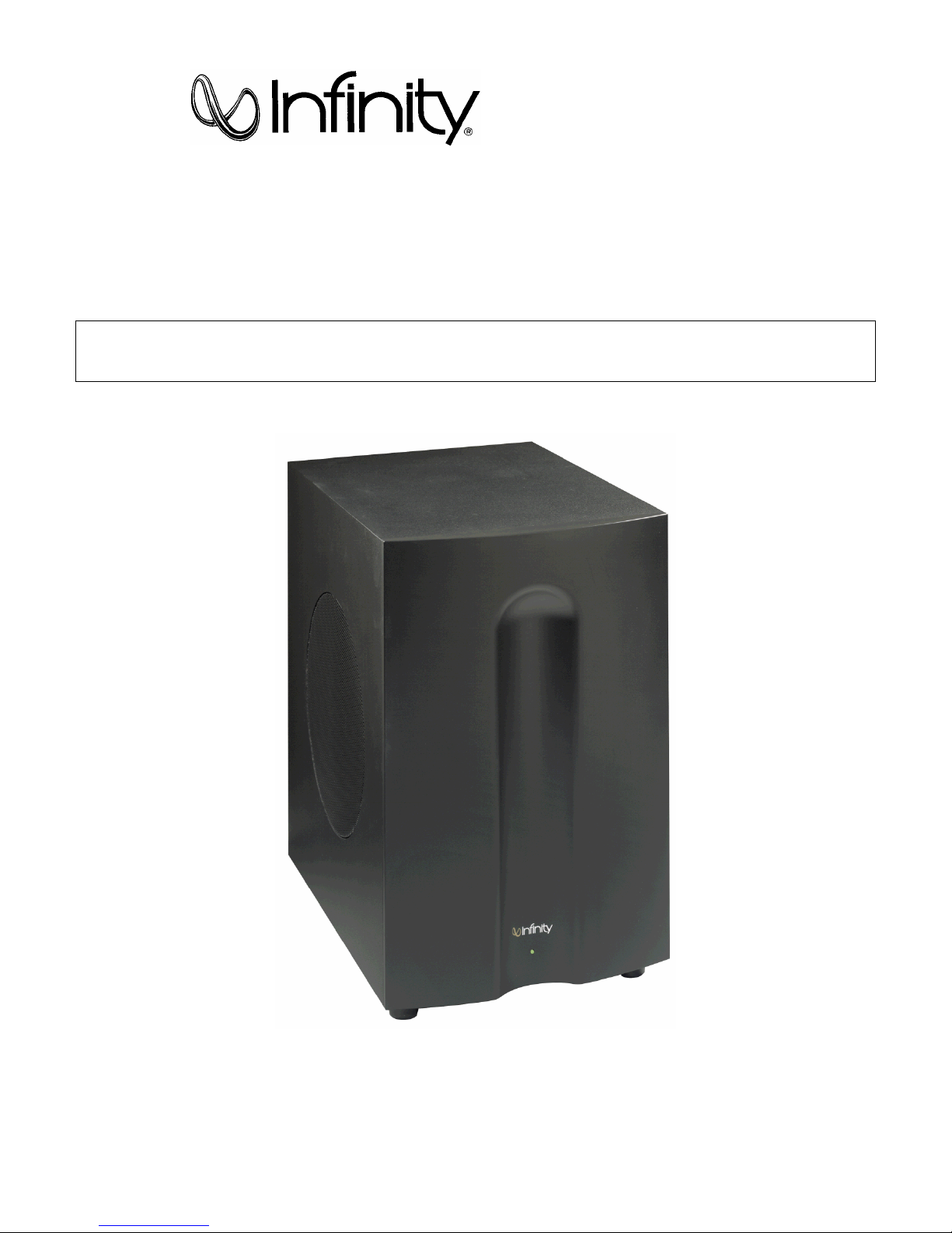
SUB450
(TSS-450 SYSTEM)
SERVICE MANUAL
Infinity Systems Incorporated
250 Crossways Park Dr.
Woodbury, New York 11797 Rev3 8/2004
Page 2

CONTENTS
BASIC SPECIFICATIONS . . . . . . . . . ………………….………….... .. . . . . . 1
DETAILED SPECIFIC ATIONS . . . . . . . . . . . . . . . . . .………. . .. .. .. . . . . . 2
CONTROLS. ………………….. .. . …………………………………... . . . . . . . 3
CONNECTIONS . . . . . . . . . . . ……….………………………………..…. . . . 4
OPERATION……. . . . . .. . . . . . . . .. .. . . . .. .. . . . . ….……… . . ... . . . . . . .5
BASIC TROUBLESHOOT ING. . . . . . . . . . . . . . . . . .….……. . .. .. .... . . . . . 6
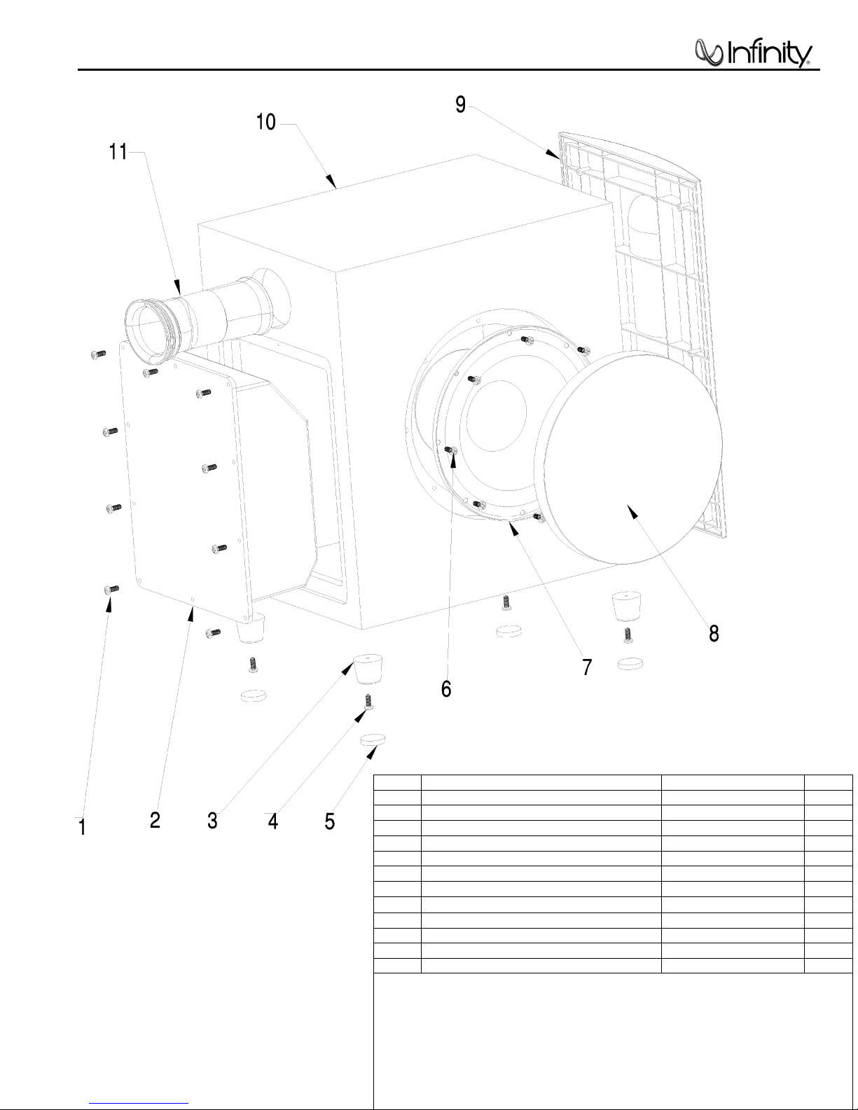
EXPLODED VIEW-MECHANICAL PARTS LIST….… . … . .. .. . . .. . … . …..7
AMPLIFIER EXPLODED VIEW . . . . . . . . . . . . . . . . .….……. . .. ..... . . . . . 8
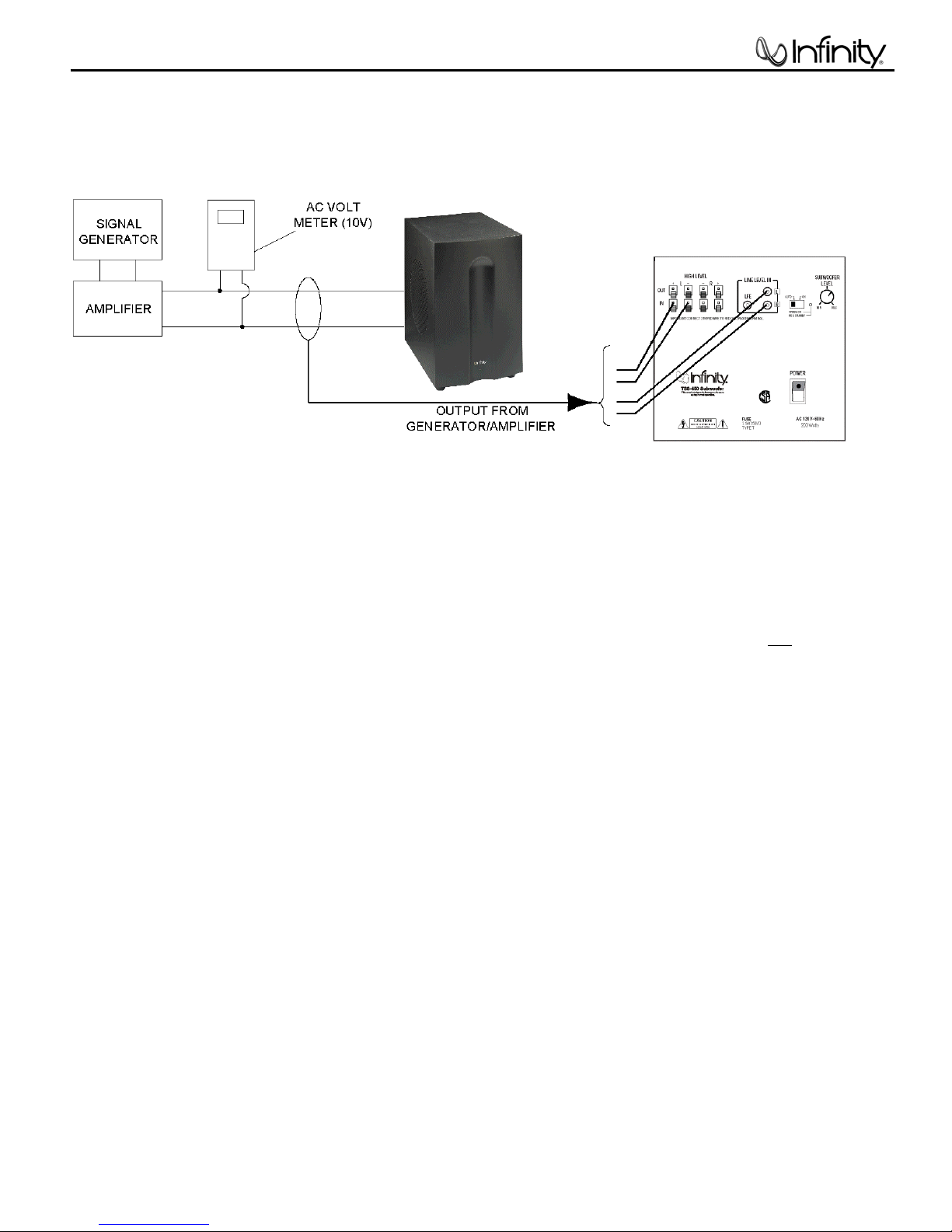
TEST SET-UP/PROCEDURE. . . . . . . . . . . . . . . . . .………. . .. .. .…. . . . . . 9
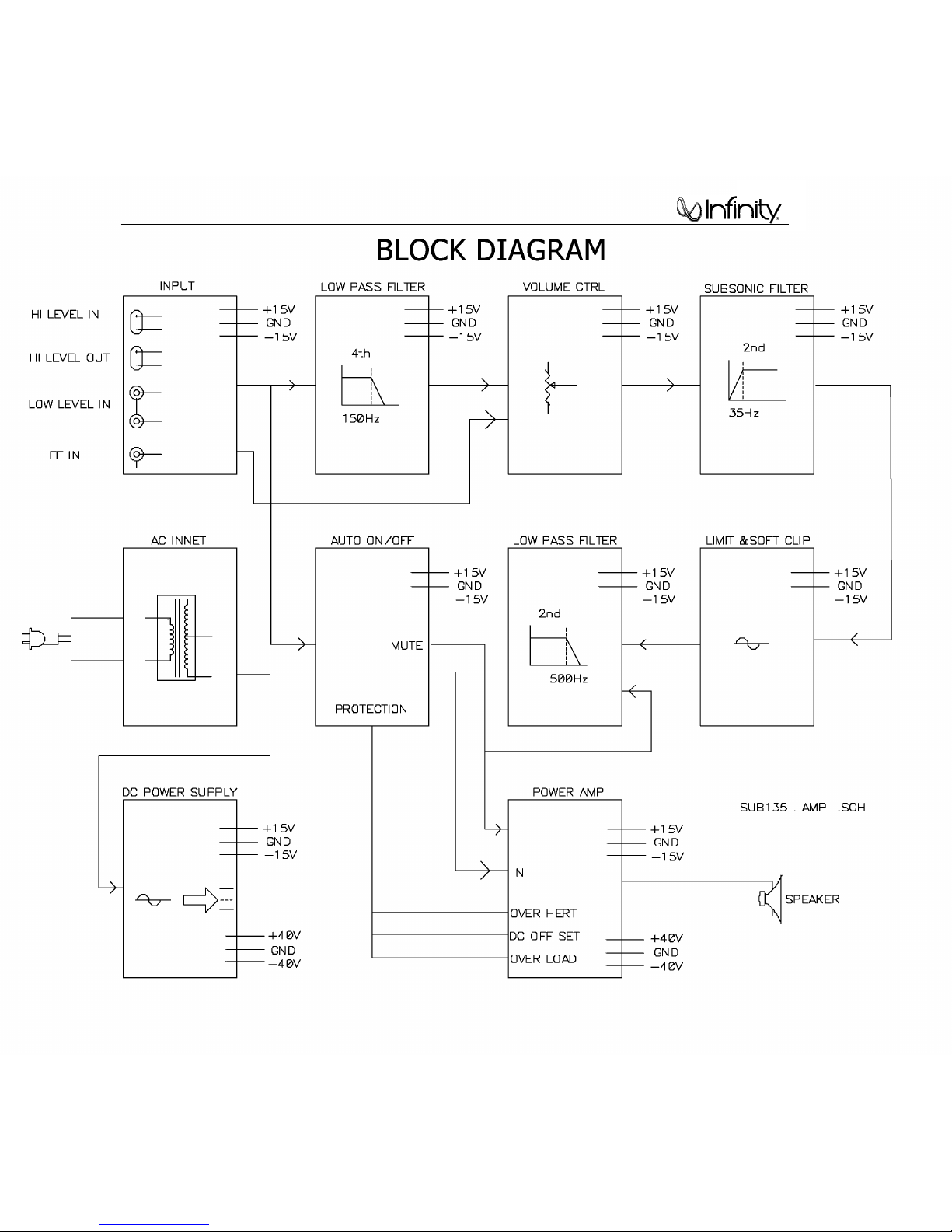
BLOCK DIAGRAM. . . . ………………... ………………………….... . . .. . … . 10
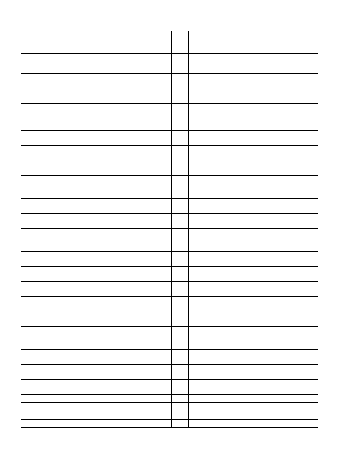
ELECTRICAL PARTS LIST …………. .... . .. . . . . . ……………………... . . . 11
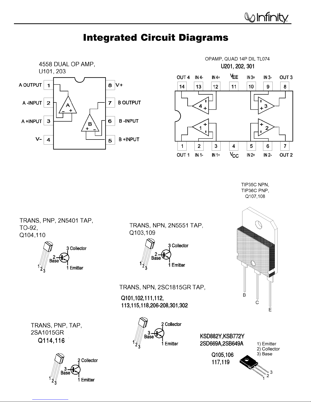
IC – TRANSISTOR PINOUTS . … . . .. . . . . . ………………………….... . . . 15
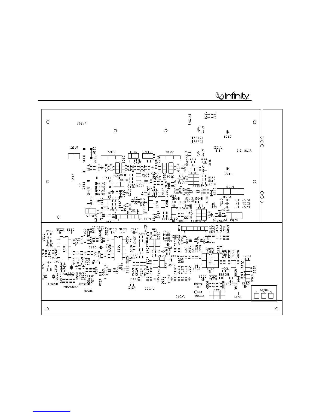
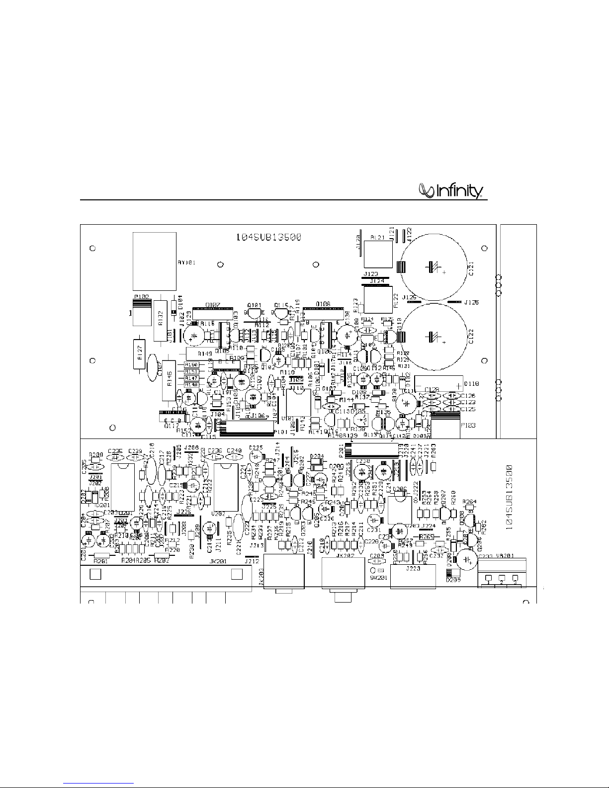
PCB DRAWINGS. .. . . . . . . . . . . . . . .. . . . . ……………………………….. …16
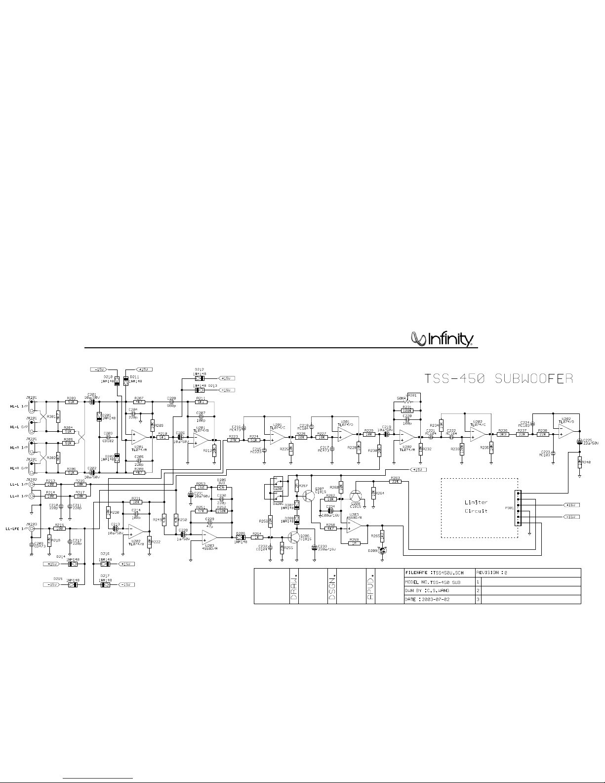
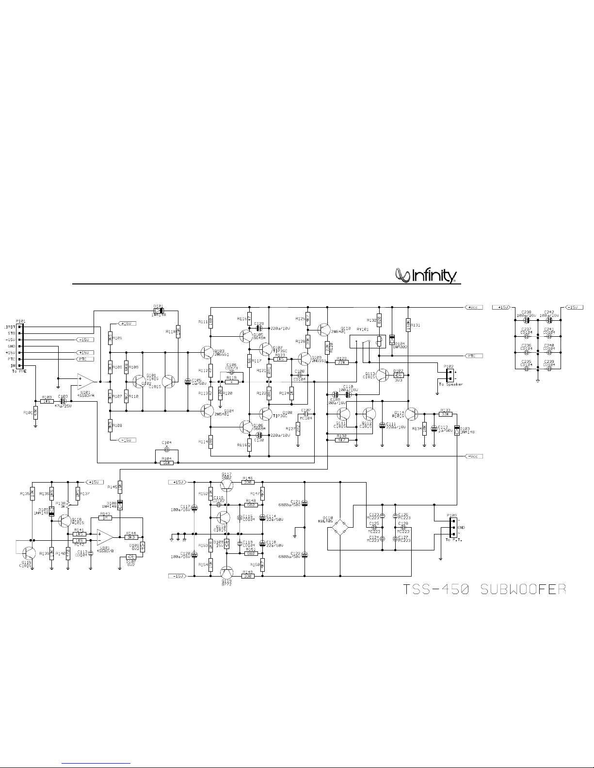
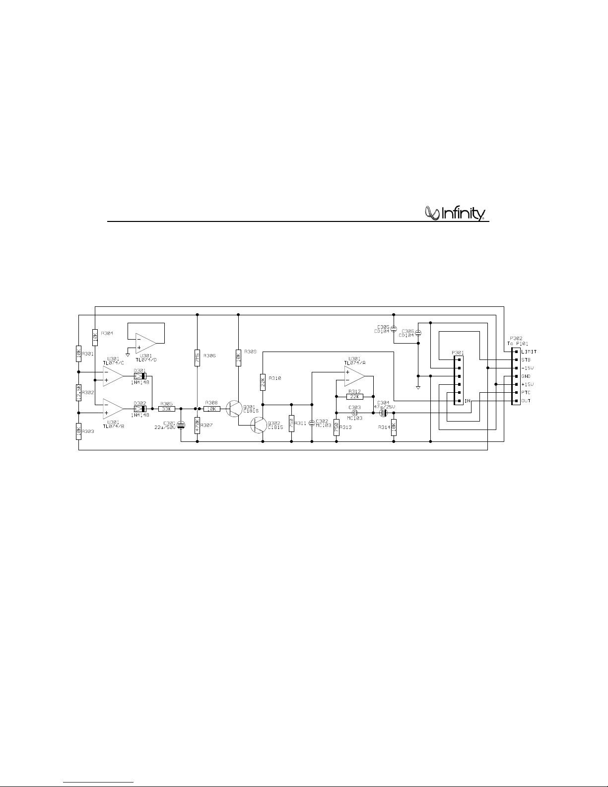
SCHEMATIC DIAGRAMS . . …………………………………….……………. . .19
WIRING DIAGRAM………………………………………….…………… .. . … .22
SUB450 Specifications
Frequency Range: 39Hz – 150Hz (±3dB)
Amplifier Output: 100 watts RMS, 500 watts Peak
Low-Frequency Driver: 8" (203mm)
Crossover Frequency: 50Hz – 150Hz, 24dB/Octave, continuously variable
Dimensions (H x W x D): 16-1/4" x 10-1/4" x 15-1/2"
Weight: 28.3 lb (12.9kg)
Infinity cont inually str ives to update and impr ove existing product s, as well as create new ones. The specifications
and construction details in this and related I nfini ty publications are therefore subject to change without notice.
(413mm x 262mm x 394mm)
1
Page 3
@50 to e put / c
SUB450
2
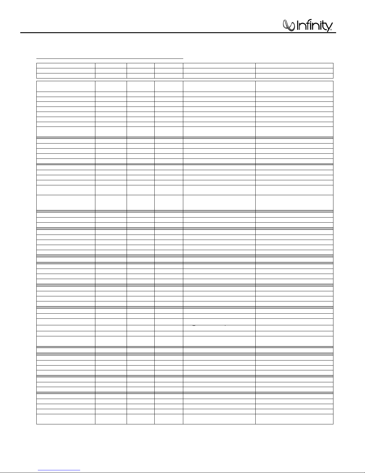
SUB450 Amplifier 100W Powered Sub/ Plate Amp
LINE VOLTAGE Yes/No Hi/Lo Line Unit Notes
Parameter Specification Unit
Amp Section
Type (Class AB, D, other) AB AB n/a External Sink required for Class AB
Load Impedance (speaker) 4 Ohms n/a Nominal Z-curve required
Rated Output Power 100 Watts 95 1 input driven
THD@ Rated Power 0.08 % 0.3 22k filter
THD @ 1 Watt 0.1 % 0.5 22k filter
DC Offset 10 mV-DC 20 @ Speaker Outputs
Damping factor >100 DF 50
Input Sensitivity
Signal to Noise
SNR-A-Weighted 100 dBA 90 rel. to rated power A-Weighting filter
SNR-unweighted 80 dBr 75 rel. to rated power 22k filter
SNR @ 1W-unweighted 60 dBr 55 rel. to 1W Output 22k filter
Residual Noise Floor 1.5 mVrms 2.5
Residual Noise Floor 1
Input Impedance
Filters
Low Pass (fixed or variable) fixed -- ±2dB
Subsonic filter (HPF) Hz ±2dB
Limiter (yes/no) YES -- n/a
Features
LFE Input YES functional BW Limited to 500 Hz
Volume pot Taper (lin/log) log -- functional
ATO YES functional
Input Configuration
Line In (L,R) L ,R -- functional RCA inputs: L , R Summed to Mono
Line level in LFE LFE functional
Spkr/Hi Level In
Signal Sensing (ATO)
Auto-Turn-On (yes/no) YES -- functional
ATO Input Frequency 50 Hz functional
ATO Level 2 mV functional
ATO Turn-on time 5 ms functional AC on, signal applied
Auto Mute/ Turn-OFF Time 15 minutes functional T before muting, after signal is removed Auto turn of time (T) must be 10 > T <15
Power on Delay time 3 sec. functional AC Power Applied
Transients/Pops
ATO Transient 5 mV-peak 10 @ Speaker Outputs
Turn-on Transient 50 mV-peak 100 @ Speaker Outputs AC Line cycled from OFF to ON
Turn-off Transient 50 mV-peak 100 @ Speaker Outputs AC Line cycled from ON to OFF
Efficiency
Stand-by Input Power 13 Watts 15 @ nom. line voltage Maximum allowable input power.
Power Cons.@rated power 185 Watts 195 @ nom. line voltage 100 Watts @ 4 Ohms nominal line voltage
Protection
Short Circuit Protection YES -- functional Direct short at output
Thermal Protection 65 deg. C -- functional @1/8 max unclipped Power rise
DC Offset Protection YES -- functional DC present at Speaker Out leads Relay or crowbar (for driver/fire protection)
Line Fuse Rating 2.5 Amps 2.5 Type-T or Slo Blo External fuse with UL/SEMKO rated holder
US 120vac/60Hz Yes 108-132 Vrms Normal Operation
Asia 100vac/50Hz Yes 90-110 Vrms Normal Operation
QA Test
Limits Conditions Notes
Measured at speaker terminals, Output
power 90 Watts THD 0.1 %
Input Frequency 50 Hz 50 Nominal Freq. 1 input driven
Line Input (L&R) 250 mVrms ±2dB To Rated Power 1 input driven
Speaker/Hi Level Input 2.5 Vrms ±2dB To Rated Power (-20 dB below Line In)...1 input driven
Line input L&R , LFE >15 K ohms n/a Nominal
Speaker/Hi Level Input 4.7 K ohms n/a Nominal
LFE Input 135 mVrms ±2dB To Rated Power LFE input driven only
Volume @max, using RMS reading
DMM/VOM (or A/P)
mVrms(max)
Slope & Q dB/Octave n/a
Slope & Q dB/Octave n/a
(L,R)
L,R -- functional L R Summed to Mono
Volume @max, w/ A/P Swept Bandpass
2
Measurement (Line freq.+ harmonics)
driven
Page 4
POWER
HIGH LEVEL
+ – – +
SUBWOOFER
LEVEL
CAUTION
RISK OF ELECTRIC SHOCK
DO NOT OPEN
OUT
IN
L R
LINE LEVEL IN
LFE
L
R
AUTO ON
MIN MAX
AC 120V~60Hz
200 Watts
FUSE
2.5A/250V
TYPE T
IMPORTANT: CONNECT STRIPED WIRE TO RED ( ) SPEAKER TERMINAL.
GREEN: ON
RED: STANDBY
+
∞
¢
§
£
™
¡
SUB450
3
S
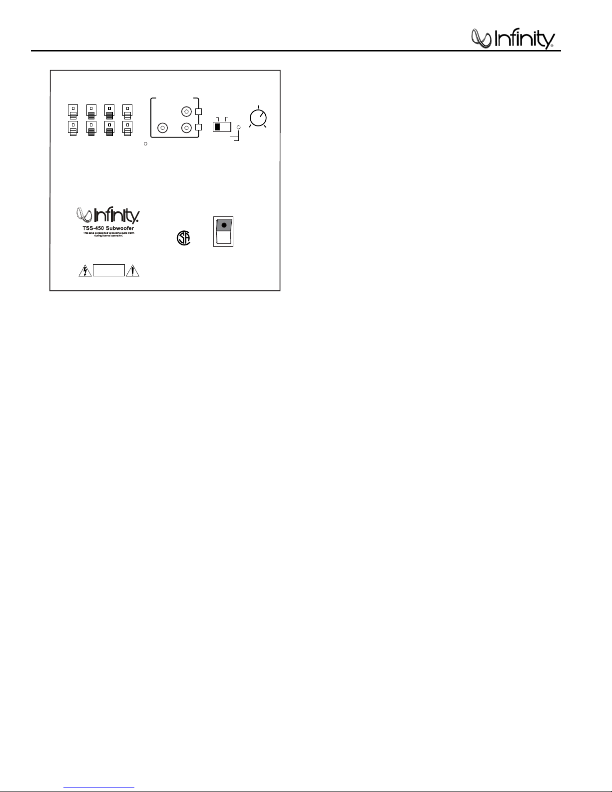
UBWOOFERCONTROLS
Rear Panel
A Few Suggestions
We recommend that you do not operate your speakers or
subwoofer with the bass,treble and loudness controls set to
full boost. This will place undue strain on your electronics and
speakers and could damage them.
The volume control setting on your processor/preamp or receiver
is not a specific indication of the overall loudness level of the
speakers.The only important consideration is the loudness level at
which the system can be played,regardless of where the volume
control is set.
Always turn down the volume control setting on your processor/
preamp or receiver when changing a cassette or CD,or switching
inputs to AM or FM operation.Excessively loud transients (clicks or
popping sounds) can damage the satellite speakers and possibly
LFE Input
Line-Level Inputs
AUTO/On Switch
the subwoofer.
Important!
Whenever changing cables,pulling plugs,etc.,ALWAYS TURN OFF
ALL EQUIPMENT,including the subwoofer.
Subwoofer Level Control
Power Switch
TSS-450
Page 5
HIGH LEVEL
+ – – +
SUBWOOFER
LEVEL
OUT
IN
L R
LINE LEVEL IN
LFE
L
R
AUTO ON
MIN MAX
GREEN: ON
RED: STANDBY
SUBWOOFER OR
LFE OUTPUT
HIGH LEVEL
+ – – +
SUBWOOFER
LEVEL
OUT
IN
L R
LINE LEVEL IN
LFE
L
R
AUTO ON
MIN MAX
GREEN: ON
RED: STANDBY
RECEIVER/PROCESSOR
HIGH LEVEL
+ – – +
SUBWOOFER
LEVEL
OUT
IN
L R
LINE LEVEL IN
LFE
L
R
AUTO ON
MIN MAX
GREEN: ON
RED: STANDBY
RECEIVER/AMPLIFIER
Front Speaker Output
LEFT RIGHT
+ – – +
LEFT SPEAKER
– +
RIGHT SPEAKER
– +
SUB450
4
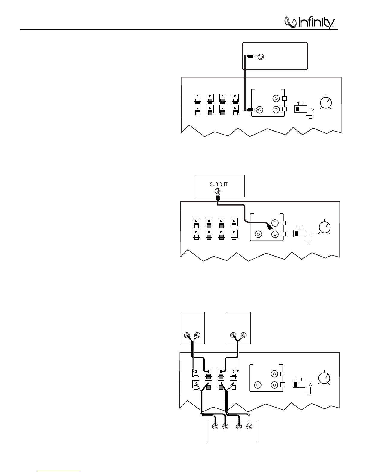
SUBWOOFER CONNECTIONS
®
If you have a Dolby* Digital or DTS
processor with a low-frequency-effects (LFE)
or subwoofer output:
If your receiver/processor does not contain
a Dolby Digital or DTS processor but has a
subwoofer output:
receiver/
15' subwoofer
cable included
Set line-level/LFE switch to “LFE.”
15' subwoofer
cable included
If your receiver/processor does not have
subwoofer outputs for the left and right
channels or an LFE output:
TSS-450
Set line-level/LFE switch to “Normal.”
NOTE:If your receiver/processor has only one sub out,
you may use either the L or R input.
Page 6

SUB450
5
O
PERATION
Surround Modes
When using the TSS-450 in a Dolby* Digital or DTS home theater
system,make sure all speakers are set to “Small”.When using the
system in a Dolby Pro Logic* home theater system,make sure the
receiver’s center channel mode is set to “Normal.”
Some Dolby Digital-equipped receivers/processors offer different
setup options for each source or surround mode,e.g., CD-stereo,
videotape,Dolby Digital, Pro Logic.In each case,follow your
equipment’s instructions to ensure that the subwoofer output is
turned on and that the speakers are set to “Small”in each mode.
If your receiver has adjustable crossover settings,we recommend
the subwoofer crossover be set between 100Hz –120Hz.
Power On
Plug your subwoofer’sAC cord into a wall outlet.Do not use the
outlets on the back of the receiver.
Initially set the Subwoofer Level Control to the“MIN”position.
Turn on the subwoofer by pressing the Power Switch on the
rear panel.
Turn on your entire audio system and start a CD or movie
soundtrack at a moderate level.
Auto On/Stand-By
With the Power Switch in the AUTO position,the LED on
the rear panel will remain lit in red or green to indicate the
On/Stand-By mode of the subwoofer.
RED = STAND-BY (No signal detected,Amp Off)
GREEN = ON (Signal detected,Amp On)
The subwoofer will automatically enter the Stand-By mode after
approximately 10 minutes when no signal is detected from your
system. The subwoofer will then power ON instantly when a signal
is detected.During periods of normal use,the Power Switch
can be left on.You may turn off the Power Switch for extended
periods of nonoperation,e.g., when you are away on vacation.
Adjust Level
Turn the Subwoofer Level Control up about half way.If no
sound emanates from the subwoofer,check the AC-line cord and
input cables.Are the connectors on the cables making proper
contact? Is the AC plug connected to a “live”receptacle? Has the
Power Switch been pressed to the “On”position? Once you
have confirmed that the subwoofer is active,proceed by playing a
CD or DVD.Use a selection that has ample bass information.
Set the overall volume control of the receiver/processor to a
comfortable level.Adjust the Subwoofer Level Control until
you obtain a pleasing blend of bass.Bass response should
not overpower the room but rather be adjusted so there is
a harmonious blend across the entire musical range.Many
users have a tendency to set the subwoofer volume too loud,
adhering to the belief that a subwoofer is there to produce lots of
bass.This is not entirely true.A subwoofer is there to enhance
bass,extending the response of the entire system so the bass
can be felt as well as heard.However,overall balance must
be maintained or the music will not sound natural.An experienced
listener will set the volume of the subwoofer so its impact on
bass response is always there but never obtrusive.
TSS-450
Page 7

If there is no sound from any
of the speakers:
• Check that receiver/amplifier
is on and a source is playing.
• Check that the powered
subwoofer is plugged in, its
Power switch is switched
on to the “•” position, and the
“Auto/On” switch is either
in the “On” or “Auto” position.
• Check all wires and connections between receiver/
amplifier and speakers. Make
sure all wires are connected.
Make sure none of the
speaker wires are frayed,
cut or punctured.
• Review proper operation of
your receiver/amplifier.
If there is no sound coming
from one speaker:
• Check the “Balance” control
on your receiver/amplifier.
• Check all wires and connections between receiver/
amplifier and speakers. Make
sure all wires are connected.
Make sure none of the
speaker wires are frayed,
cut or punctured.
• In Dolby Digital or DTS
modes, make sure that the
receiver/processor is
configured so that the speaker
in question is enabled.
If there is no sound from the
center speaker:
• Check all wires and
connections between
receiver/amplifier and
speaker. Make sure all wires
are connected. Make sure
none of the speaker wires are
frayed, cut or punctured.
• If your receiver/processor is
set in Dolby Pro Logic mode,
make sure the center speaker
is not in phantom mode.
• If your receiver/processor
is set in Dolby Digital or DTS
mode, make sure the
receiver/processor is configured so that the center
speaker is enabled.
If the system plays at low
volumes but shuts off as
volume is increased:
• Check all wires and connections between receiver/
amplifier and speakers. Make
sure all wires are connected.
Make sure none of the
speaker wires are frayed, cut
or punctured.
• If more than one pair of main
speakers is being used, check
the minimum impedance
requirements of your
receiver/amplifier.
If there is low (or no) bass
output:
• Make sure the connections
to the left and right “Speaker
Inputs” have the correct
polarity (+ and –).
• Make sure the subwoofer
is plugged into an active
electrical outlet.
• Make sure the powered
subwoofer is plugged in
and is either in the “On” or
“Auto” position.
• In Dolby Digital or DTS
modes, make sure your
receiver/processor is
configured so that the subwoofer and LFE output
are enabled.
If there is no sound from
the surround speakers:
• Check all wires and con-
nections between receiver/
amplifier and speakers. Make
sure all wires are connected.
Make sure none of the
speaker wires are frayed, cut
or punctured.
• Review proper operation of
your receiver/amplifier and its
surround-sound features.
• Make sure the movie or TV
show you are watching is
recorded in a surround-sound
mode. If it is not, check to see
if your receiver/ amplifier has
other surround modes you
may use.
• In Dolby Digital or DTS
modes, make sure your
receiver/processor is
configured so that the
surround speakers are
enabled.
• Review the operation of your
DVD player and the jacket of
your DVD to make sure that
the DVD features the desired
Dolby Digital or DTS mode,
and that you have properly
selected that mode using both
the DVD player’s menu and the
DVD disc’s menu.
TROUBLESHOOTING
Staple sales invoice here.
SUB450
6
Page 8
7
SUB450
Ref# Description Part Number Qty
1 Screw, Amplifier 352-AM04020D210 10
2 SUB450 Amplifier Ass’y Not for Sale 1
3 Feet 320-RUB-00195 4
4 Screw, Foot 352-CM04025D604 4
5 Foot Pad 320-RUB-00199 4
6 Screw, Woofer 352-FM04020D605 8
7
8” (203mm) Woofer DCR = 3.3Ω ±10%
8 Grille 329-080-00736B/S 1
9 Front Faceplate Not for Sale 1
10 SUB450 cabinet Not for Sale 1
11 Port Tube 249-HIPS-00172B/S 1
20MF10DAG-DW01 1
SERVICE NOTE
Access to woofer:
1) Carefully pry metal grille out of its recess with a sharp pointed instrument
such as an awl – USE CAUTION. Work evenly around the perimeter
until the grill can be removed.
2) Remove the (8) Phillips screws holding the woofer to the cabinet.
3) After service, replace the woofer and re-insert the grille back into its
recess until it’s fully seated.
Page 9

n
f
e
g
l
d
m
c
b
k
n
h
m
h
q
c
r
l
r
q
o
p
k
p
o
a
SUB450 AMPLIFIER EXPLODED VIEW
SUB450
8
Page 10
SUB450
9
Test Set Up and Procedure
Equipment needed:
• Function/signal generator/sweep generator
• Integrated Amplifier
• Multimeter
• Speaker cables
General Unit Function (UUT = Unit Under Test)
1) From the signal generator, connect one line level (RCA) cable to the Subwoofer Line Level Input jacks L/R
on the UUT. Use a Y-cable from a mono source if necessary to connect to both inputs. Do not
the single LFE input.
2) On the front of the unit, turn the LEVEL control full counterclockwise.
3) Turn on generator, adjust to 100mV, 50 Hz.
4) Plug in UUT; turn the power switch ON. LED should be Red. Turn LEVEL control full clockwise (MAX)
5) LED should now be Green; immediate bass response should be heard and felt from port tube opening.
6) Turn off generator, turn LEVEL control fully counterclockwise, disconnect RCA cable.
7) Connect one pair of speaker cables to Speaker Level input terminal (IN) on UUT. Cables should be
connected to an integrated amplifier fed by the signal generator.
8) Turn on generator and adjust so that speaker level input at the amplifier is 2.0V, 50 Hz. Turn LEVEL control
full clockwise.
9) Green LED should light, immediate bass response should be heard and felt from the port tube opening.
Sweep Function
1) Follow steps 7-9 above, using a sweep generator as a signal source.
2) Sweep generator from 20Hz to 300Hz. Listen to the cabinet and drivers for any rattles, clicks, buzzes or
any other noises. If any unusual noises are heard, remove woofers and test.
Driver Function
1) Remove woofer from cabinet; detach + and - wire clips.
2) Check DC resistance of woofer; it should be 3.3 ohms ±10%
3) Connect a pair of speaker cables to driver terminals. Cables should be connected to an integrated amplifier
fed by a signal generator. Turn on generator and adjust so that speaker level output is 5.0V.
4) Sweep generator from 20Hz to 1kHz. Listen to driver for any rubbing, buzzing, or other unusual noises.
connect to
Page 11
SUB450
10
Page 12
SUB 450 Electrical Parts List
11
Part Number Description
Resistors
110-14122j26 RES 1.2K 1/4W 5% CF 26mm
110-14472j26 RES 4.7K 1/4W 5% CF 26mm
110-14681j26 RES 680 1/4W 5% CF 26mm
110-16101j26 RES 100 1/6W 5% CF 26mm
110-16102j26 RES 1K 1/6W 5% CF 26mm
110-16103j26 RES 10K 1/6W 5% CF 26mm
110-16104j26 RES 100K 1/6W 5% CF 26mm
110-16105j26 RES 1M 1/6W 5% CF 26mm
110-16123j26 RES 12K 1/6W 5% CF 26mm
110-16124j26 RES 120K 1/6W 5% CF 26mm
110-16151j26 RES150 1/6W 5% CF 26mm
110-16152j26 RES 1.5K 1/6W 5% CF 26mm
110-16153j26 RES 15K 1/6W 5% CF 26mm
110-16154j26 RES 150K 1/6W 5% CF 26mm
110-16181j26 RES 180 1/6W 5% CF 26mm
110-16182j26 RES 1.8K 1/6W 5% CF 26mm
110-16183j26 RES 18K 1/6W 5% CF 26mm
110-16223j26 RES 22K 1/6W 5% CF 26mm
110-16273j26 RES 27K 1/6W 5% CF 26mm
110-16205j26 RES 2M 1/6W 5% CF 26mm
110-16332j26 RES 3.3K 1/6W 5% CF 26mm
110-16333j26 RES 33K 1/6W 5% CF 26mm
110-16392j26 RES 3.9K 1/6W 5% CF 26mm
110-16393j26 RES 39K 1/6W 5% CF 26mm
110-16470j26 RES 47 1/6W 5% CF 26mm
110-16471j26 RES 470 1/6W 5% CF 26mm
110-16472j26 RES 4.7K 1/6W 5% CF 26mm
110-16473j26 RES 47K 1/6W 5% CF 26mm
110-16474j26 RES 470K 1/6W 5% CF 26mm
110-16512j26 RES 5.1K 1/6W 5% CF 26mm
110-16513j26 RES 51K 1/6W 5% CF 26mm
110-16560j26 RES 56 1/6W 5% CF 26mm
110-16563j26 RES 56K 1/6W 5% CF 26mm
110-16682j26 RES 6.8K 1/6W 5% CF 26mm
110-16751j26 RES 750 1/6W 5% CF 26mm
110-16755j26 RES 7.5M 1/6W 5% CF 26mm
110-16913j26 RES 91K 1/6W 5% CF 26mm
110-10821jk1 RES 820 1W 5% 5mm
110-122r2j15 RES 2.2 1/2W 5% 15mm
110-20331jk2 Resistor 330Ω 2W ±5%
110-20331jk3 Resistor 330Ω 2W ±5%
114-03302m0 Semi-solid resistor 3K 0.3W ±20%
115-h503a101 VR D16 50K/1 A LEVEL POT
110-16153j26 Resistor 15K 1/6W ±5% CF 26mm
113-50r10j20 Resistor 0.1Ω 5W ±5%
Qty
Reference Designator
1
R265
4
R147,150,201,202
2
R148,151
4
R120,213,214,215
2
R124,254
R134,209,212,216,217,220,221,222,225,226,228,229,
25
230,232,235,240,260,264,301,303,304,308,309,314
1
R231
2
R143,259
2
R135,139
1
R233
1
R253
6
R103,123,136,137,141,142
5
R118,145,152,154,234
2
R131,252
2
R111,114
1
R153
2
R227,262
10
R128,129,133,237,238,255,256,263,310,312
1
R223
1
R257
5
R106,107,144,236,258
1
R305
2
R105,108
1
R126
4
R112,113,115,116
1
R140
5
R110,125,130,207,208
5
R101,219,249,250,251
1
R307
2
R210,211
1
R224
1
R117
1
R104
1
R109
2
R311,313
1
R306
4
R203,204,205,206
1
R132
1
R127
1
R146
1
R149
R138
1
1
VR201
1
R302
R121,122
2
Page 13
Part Number Description
12
Capacitors
Qty
Reference Designator
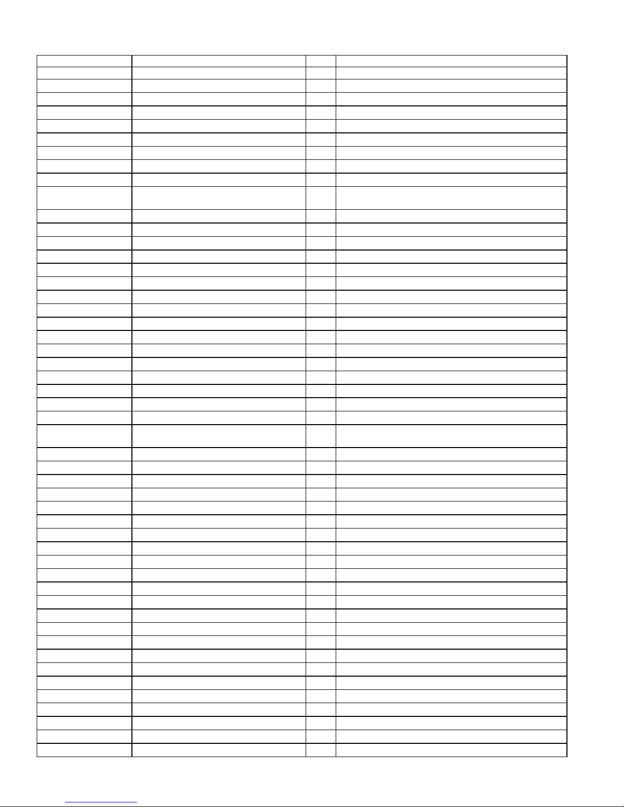
130-3f472md00 Ceramic Cap 4700pf 400v +/- 20%
130-2b101k503 CD 100P 50V 10%
130-2b102k503 CD 1000P 50V 10%
130-2b221k503 CD 220P 50V 10%
130-2b681k503 CD 680P 50V 10%
130-2f104z503 CD 0.1U 50V +80/-20%
130-3f473m503 CD 0.047U 50V 20%
130-sl470k503 CD 47P 50V 10%
132-103j503 MC 0.01U 50V 5%
132-104j503 MC 0.1U 50V 5%
132-223ja03 MC 0.022U 100V 5%
132-473j503 MC 0.047U 50V 5%
132-103j503 MC 0.01U 50V 5%
135-3105m50 EC 1U 50V 20%
135-3106m50 EC 10U 50V 20%
135-3107m16 EC 100U 16V 20%
135-3226m50 EC 22U 50V 20%
135-3227m10 EC 220U 10V 20%
135-3227m16 EC 220U 16V 20%
135-3476m25 EC 47U 25V 20%
132-223ja03 MC 0.022U 100V 5%
135-3107M16 EC 100U 16V 20%
1
ON POWER SWITCH
3
C207,214,220
2
C116,203
6
C204,205,210,211,212,230
1
C208
C108,113,115,119,232,235,236,237,239,240,241,305,
13
306
2
C106,209
1
C229
2
C223,224
4
C107,218,221,222
5
C124,125,126,128,215
2
C216,217
2
C302,305
3
C105,112,228
6
C201,202,206,213,219,231
6
C109,117,120,234,238,242
4
C114,118,225,301
2
C129,130
2
C111,233
1
C103,304
2
C123,127
1
C110
135-4688m50 EC 6800U 50V 20% D25X45mm
Semiconductors
192-027c1815gr TR 2SC1815GR NPN
192-028a1015gr TR 2SA1015GR PNP
192-1672n5551 TR 2N5551 NPN
192-1682n5401 TR 2N5401 AI-PNP 500mA TO-92
197-131n4148 DIODE 1N4148 26mm
199-15000335 ZENER 3.3V 1/2W 26mm
199-15000625 ZENER 6.2V 1/2W 26mm
199-15001605 ZENER 16V 1/2W 26mm
192-021c1815gr TR 2SC1815GR NPN
192-991d669a TR 2SD669A NPN
192-021tip35c TR TIP35C NPN
192-992b649t TR 2SB649A PNP
192-022tip36c TR TIP36C PNP
192-201d882y TR KSD882Y PNP
192-202b772y TR KSB772Y PNP
190-06m4558d IC OPA 4558D DUAL OP-AMP
190-16tl074cn IC TL074CN ST QUAD OP-AMP
195-10204hgw LED 204HGW
197-101n4002 DIODE 1N4002
197-131n4148 DIODE 1N4148
C121,122
2
8
Q102,111,112,113,118,206,207,208
2
Q114,116
2
Q103,109
2
Q104,110
9
D101,103,105,108,201,202,206,207,208
2
D102,205
2
D106,107
1
D109
4
Q101,115
1
Q106
1
Q107
1
Q105
1
Q108
1
Q117
1
Q119
2
U101,203
3
U201,202,301
1
D209
1
D104
2
D301,302
Page 14
Part Number Description
13
Qty
Reference Designator
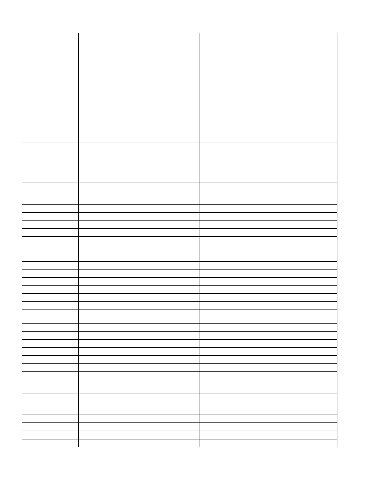
197-00kbl405 BD 4A 500V KBL405 BRIDGE
192-027c1815gr Transistor 2SC1815GR
162-50332003 2PIN 330mm RED LED 1 D209
Miscellaneous
156-b010010 TUBE 1*10mm
171-udhss124d RELAY 5A 24V UDH-SS124D
174-0rcb202v RCA JACK RCB-202V
174-0rcb242v1 JACK RCA RCB-242V-1
174-2rsp108v 8PIN SPK JACK RSP-108V
193-3m2520 ISLATOR MICA TO-3P 25*20mm
180-tms7210v SW210 AUTO/ON SLIDE SWITCH
180-PBR12C11S POWER PUSH SW. BR12C11S
152-U602015 AC CORD SVT FT-2 6FT
155-520020 FUSE HOLDER R3-11
154-U25006T0 FUSE 2.5A 250V 20mm
700-KB800 SUB. LEVEL KNOB
150-E8604107
351-AM03008A079 Screw M3*8 black 6
351-HM04016A218 Screw M4*16 black 4
354-GM04002 Screw with screw plate M4 4
352-AM03008D040
352-AM03010D065
350-EM04012D024
152-u602015 Power wire SVT FT-26FT 1
162-10082007 Wire red 18AWG 80mm 1
162-a040d001 Speaker wire #1015 400mm 1
176-wjce1 Closing terminal CE-1 1
302-AL-00118-0VD Alu. panel 215*270*2.5t 1
323-AL-00108 HEAT SINK 117.5*60*25 1
311-ABS-00028 Plastic knob 46077-W P.V.C. 1
TRANSFORMER EI-86 60HZ 120V
TT0869906580
Screw 3*8 type B black
Screw 3*10 type P black
Screw 4*12 black
1
D110
2
Q301,Q302
2
FOR Q101,115
1
RY101
1
JK202
1
JK203
1
JK201
2
FOR Q107,108
1
1
1
1
1
1
1
8
4
4
306-ABS-00004 Plastic cover 268*213*102A.B.S UL 1
333-EVA-00096 EVA caution 213*15*2.0mm 2
333-EVA-00097 EVA caution 213*15*1.0t 2
333-EVA-00132 EVA caution 238*15*2.0mm 2
333-EVA-00133 EVA caution 238*15*1.0t 2
333-EVA-00220 EVA caution 225*15*1t UL 1
320-RUB-00033 Rubber sheet 25*21*4t 4
362-FE-00013 PCB holder L TYPE t=1.6mmS.P.C.C 2
175-1c07v01 Connector 7PIN PITCH=2.5mm 1 P101
175-1d02v01 Connector 2PIN PITCH=3.96mm 1 P102
175-1d03v01
193-3m2520 Piezo TO-3P 25x20mm
323-AL-00020 HEAT SINK 65*32*31 1
361-NYL-00054 Diode insulated sheet (SW06002) 2
Connector 3 PIN PITCH=3.96mmJST-VH
1 P103
2
for Q107,Q108
Page 15

Part Number Description
14
361-FE-00051 Diode solid sheet 14.2*8.0*5.2t=1.6mm 1
156-h010010 Heat thimble 1ψ*10mm 2
Qty
Reference Designator
162-50129001 CABLE ASS'Y 120mm AWG28WHT
175-9f40hr2
162-10059001 Wire 50mm WHITE UL1007 AWG266:6
Connector 40PIN
PITCH=2.54mmHR2*40
P302
1
1
Page 16
SUB450
15
Page 17
SUB450
16
Page 18
SUB450
17
Page 19

SUB450
18
Page 20
SUB450
19
Page 21
SUB450
20
Page 22
21
SUB450
Page 23

SUB450
 Loading...