

Page 1

FOREWORD
Your INFINITI represents a new way of thinking
about vehicle design. It integrates advanced engineering and superior craftsmanship with a simple,
refined aesthetic sensitivity associated with traditional Japanese culture.
The result is a different notion of luxury and beauty.
The car itself is important, but so also is the sense
of harmony that the vehicle evokesinitsdriver, and
the sense of satisfaction you feel with the INFINITI
—from the way it looks and drives to the high level
of retailer service.
To ensure that you enjoy your INFINITI to the
fullest, we encourage you to read this Owner’s
Manual immediately. It explains all of the features,
controls and performance characteristics of your
INFINITI; italsoprovides important instructions and
safety information.
A separate Warranty Information Booklet is
to be found in your Owner’s literature portfolio. Always carry it with you when you take
your INFINITI to an authorized retailer. The
portfolio contents provide complete information about all warranties covering this
vehicle, the periodic maintenance required
to keep the warranties in effect as well as
the INFINITI Roadside Assistance program.
Additionally, a separate Customer Care and
Lemon Law Information Booklet will explain
how to resolve any concerns you may have
with your vehicle, as well as clarify your
rights under your state’s lemon law.
INFINITI is dedicated to providing a satisfying
ownership experience for as long as you own your
car. Should you have any questions regarding your
INFINITI or your INFINITI retailer, please contact
our Consumer Affairs department at 1-800-662-
6200. In Hawaii 1-808-836-0848 (Oahu number).
In Canada 1-800-361-4792. Thank you.
READ FIRST — THEN DRIVE
SAFELY
Before driving your vehicle please read your
Owner’s Manual carefully. This will ensure
familiarity with controls and maintenance requirements, assisting you in the safe operation of your vehicle.
WARNING
IMPORTANT SAFETY
INFORMATION
REMINDERS FOR SAFETY!
Follow these important driving rules
to help ensure a safe and comfortable trip for you and your passengers!
O Never drive under the influence of
alcohol or drugs.
O Always observe posted speed
limits and never drive too fast for
conditions.
O Always use your seat belts and
appropriate child restraint systems. Preteen children should be
seated in the rear seat.
O Always provide information about
the proper use of vehicle safety
Page 2

features to all occupants of the
vehicle.
O Always review this Owner’s
Manual for important safety information.
MODIFICATION OF YOUR
VEHICLE
This vehicle should not be modified.
Modification could affect its performance, safety or durability, and may
even violate governmental regulations. In addition, damage or performance problems resulting from
modification may not be covered
under INFINITI warranties.
WHEN READING THE
MANUAL
This manual includesinformationforall
options available on this model. There-
fore, you may find some information
that does not apply to your vehicle.
All information, specifications and illustrations in this manual are those in effect at the
time of printing. INFINITI reserves the right to
change specifications or design at any time
without notice.
IMPORTANT INFORMATION
ABOUT THIS MANUAL
You will see various symbols in this manual.
They are used in the following ways:
WARNING
This is used to indicate the presence
of a hazard that could cause death or
serious personal injury. To avoid or
reduce the risk, the procedures must
be followed precisely.
CAUTION
This is used to indicate the presence
of a hazard that could cause minor or
moderate personal injury or damage
to your vehicle. To avoid or reduce
the risk, the procedures must be followed carefully.
Page 3

SII0151
If you see this symbol, it means Do not do
this or Do not let this happen.
© 2002 NISSAN MOTOR CO., LTD.
TOKYO, JAPAN
All rights reserved. No part of thisOwner’s Manual may be
reproduced or stored in a retrieval system, or transmitted
in any form, or by any means, electronic, mechanical,
photocopying, recording or otherwise, without the prior
written permission of Nissan Motor Co., Ltd.
CALIFORNIA PROPOSITION
65 WARNING
WARNING
Engine Exhaust, some of its constituents,and certain vehiclecomponents
contain or emit chemicals known to
State of California to cause cancer
and birth defects or other reproductive harm.
Page 4

TABLE OF CONTENTS
SEATS, RESTRAINTS AND SUPPLEMENTAL AIR BAG SYSTEMS ................... 1-1
INSTRUMENTS AND CONTROLS .......................................................... 2-1
PRE-DRIVING CHECKS AND ADJUSTMENTS............................................ 3-1
HEATER, AIR CONDITIONER AND AUDIO SYSTEMS .................................. 4-1
STARTING AND DRIVING................................................................... 5-1
IN CASE OF EMERGENCY .................................................................. 6-1
APPEARANCE AND CARE................................................................... 7-1
DO-IT-YOURSELF ............................................................................ 8-1
MAINTENANCE ............................................................................... 9-1
TECHNICAL AND CONSUMER INFORMATION ......................................... 10-1
INDEX ........................................................................................ 11-1
Page 5

Page 6

1 SEATS, RESTRAINTS AND SUPPLEMENTAL AIR BAG SYSTEMS
Seats............................................................ 1-2
Front power seat adjustment................. 1-3
Folding rear seat .................................... 1-4
Head restraint adjustment...................... 1-5
Active head restraint (Front seats)......... 1-6
Armrest................................................... 1-7
Supplemental restraint system.................... 1-7
Precautions on supplemental restraint
system.................................................... 1-7
Supplemental air bag warning labels... 1-20
Supplemental air bag warning light..... 1-20
Seat belts .................................................. 1-22
Precautions on seat belt usage........... 1-22
Child safety........................................... 1-26
Pregnant women.................................. 1-27
Injured persons.................................... 1-28
Three-point type seat belt with
retractor................................................ 1-28
Seat belt extenders.............................. 1-31
Seat belt maintenance ......................... 1-32
Child restraints .......................................... 1-32
Precautions on child restraints ............ 1-32
Installation on rear seat center or outboard
positions............................................... 1-34
LATCH (Lower Anchors and Tether for
Children) System.................................. 1-39
Top tether strap child restraint ........... 1-41
Installation on front passenger seat.... 1-42
Page 7
SEATS, RESTRAINTS AND SUPPLEMENTAL AIR BAG SYSTEMS
SEATS
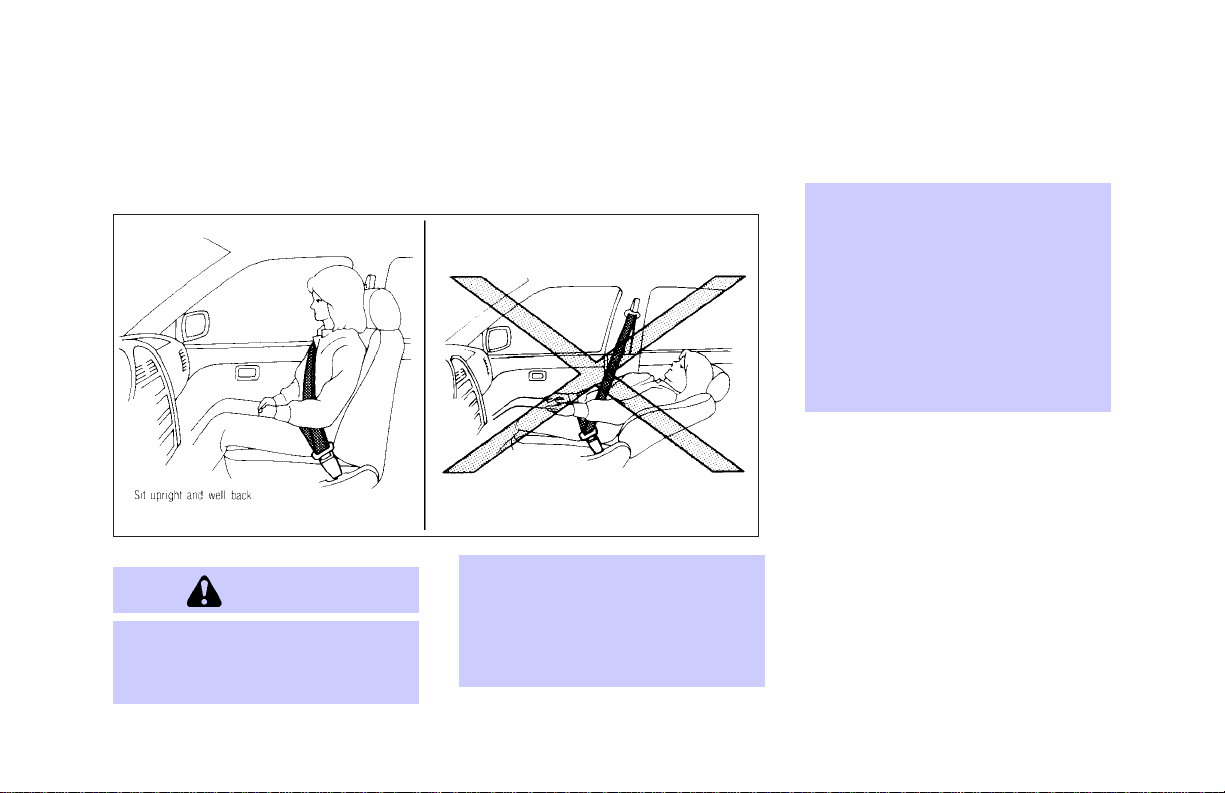
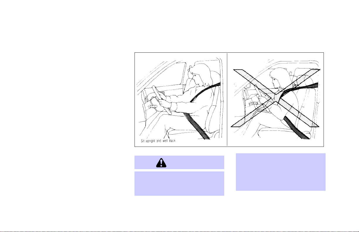
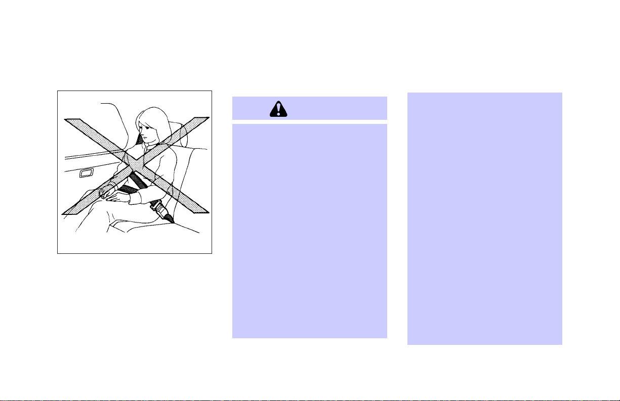
WARNING
O
Do not ride in a moving vehicle
when the seatback is reclined.
This can be dangerous. The
1-2
SIR0091
shoulder belt will not be against
your body. In an accident you
couldbethrowninto it and receive
neckorother seriousinjuries.You
could also slide under the lap
belt and receive serious internal
injuries.
O
For most effective protection
when the vehicle is in motion, the
seat should be upright. Always sit
well back in the seat and adjust
the seat belt properly. See “Precautions on seat belt usage” later
in this section.
Page 8
SEATS, RESTRAINTS AND SUPPLEMENTAL AIR BAG SYSTEMS
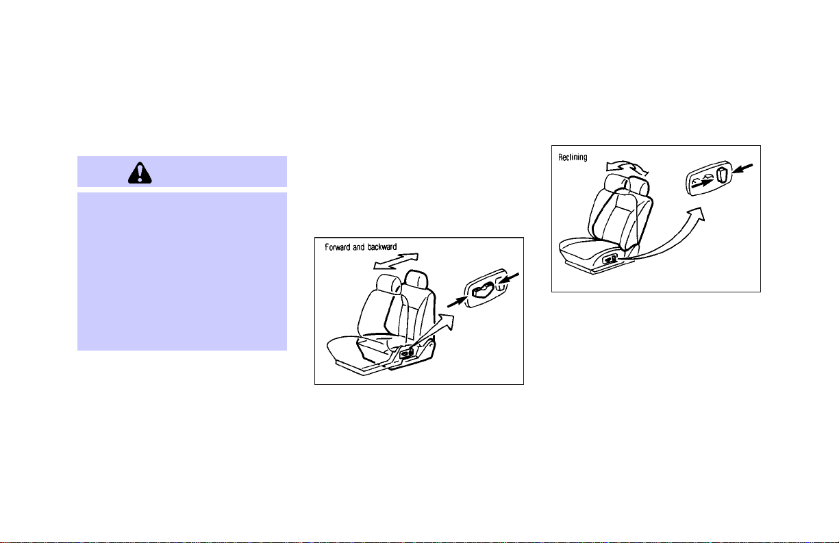
FRONT POWER SEAT ADJUSTMENT
WARNING
O
Do not adjust the driver’s seat
while driving so full attention may
be given to vehicle operation.
O
Do not leave children unattended
inside the vehicle. They could
unknowingly activate switches or
controls. Unattended children
could become involved in serious
accidents.
For memory seat information see “Auto-
matic drive positioner” in the “3. Pre-driving
checks and adjustments” section.
Operating tips
O The motor has an auto-reset overload
protection circuit. If the motor stops during
operation, wait 30 seconds, then reactivate
the switch.
O Do not operate the power seat for a long
period of time when the engine is off. This
will discharge the battery.
Forward and backward
SIR0109
Moving the switch forward or backward will
slide the seat forward or backward to the
desired position.
Reclining
SIR0110
Move the recline switch backward until the
desired angle is obtained. To bring the seatback forward again, move the switch forward
and move your body forward. The seatback
will move forward.
1-3
Page 9
SEATS, RESTRAINTS AND SUPPLEMENTAL AIR BAG SYSTEMS
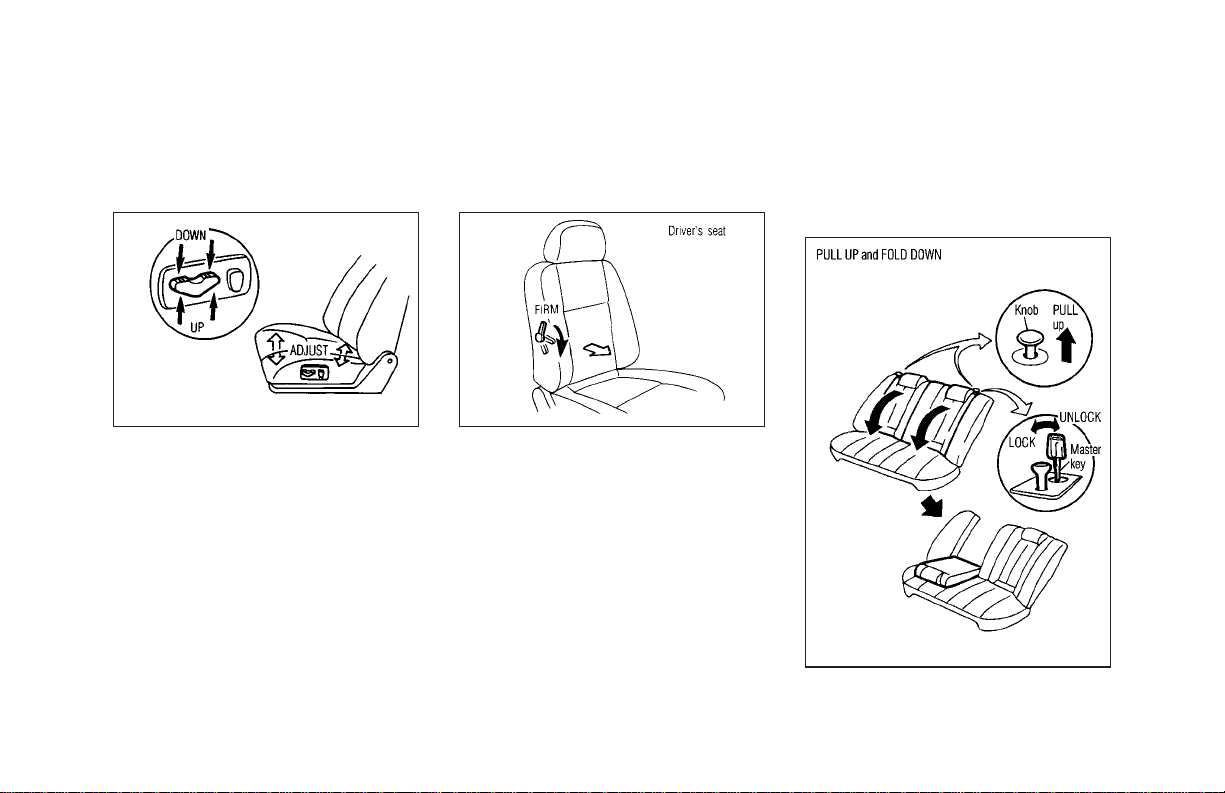
Seat lifter (Driver’s seat)
SIR0133 SIP0117
Push the front or rear end of the switch to
adjust the angle and height of the seat
cushion.
1-4
Lumbar support (Driver’s seat)
The lumbar support feature provides lower
back support to the driver. Move the lever up
or down to adjust the seat lumbar area.
FOLDING REAR SEAT
Interior trunk access
SIR0156
Page 10
SEATS, RESTRAINTS AND SUPPLEMENTAL AIR BAG SYSTEMS
Pull up on the release knob to access the
trunk from the rear seat.
The rear seats can be locked using the
master key to prevent unauthorized access.
WARNING
O
When returning the seatbacks to
the upright position, be certain
that they are completely secured
in the latched position. If they are
not completely secured in the
latched position, passengers may
be injured in an accident or sudden stop.
O
Never allow anyone to ride in the
luggage area or on the rear seat
when it is in the fold-down position. Use of these areas by pas-
sengers without proper restraint
can be extremely dangerous in an
accident or sudden stop.
O
Properly secure all cargo to help
prevent it from sliding or shifting.
Do not place cargo higher than
the seatbacks. In a sudden stop or
collision, unsecured cargo could
cause personal injury.
O
Closely supervise children when
they are around cars to prevent
them from playing and becoming
locked in the trunk where they
could be seriously injured. Keep
the car locked with the rear seatback securely latched when not in
use, and prevent children’s access to car keys.
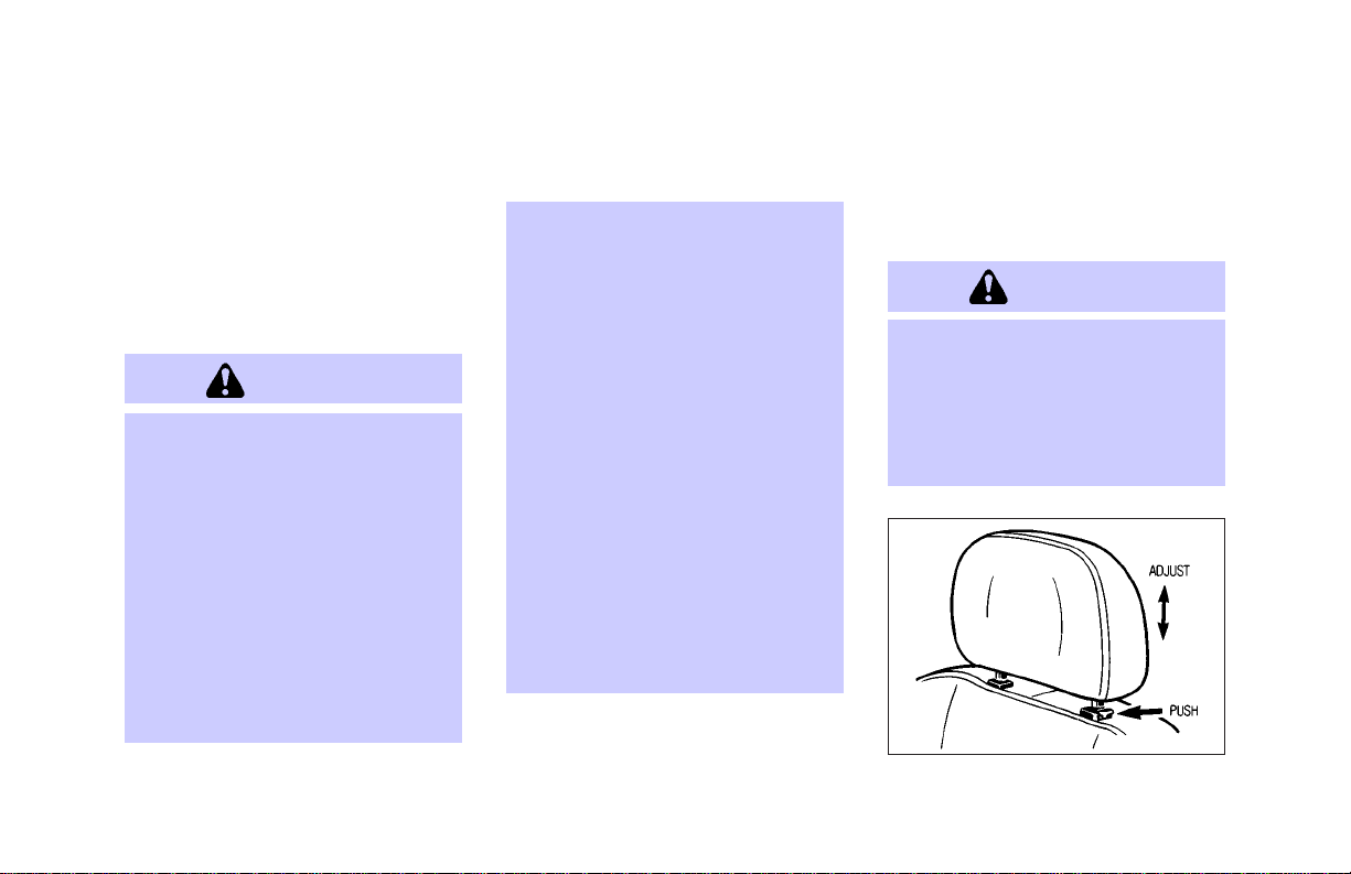
HEAD RESTRAINT ADJUSTMENT
WARNING
Head restraints should be adjusted
properly as they may provide significant protection against injury in an
accident.Donot remove them.Check
the adjustment after someone else
uses the seat.
SIR0088B
1-5
Page 11
SEATS, RESTRAINTS AND SUPPLEMENTAL AIR BAG SYSTEMS
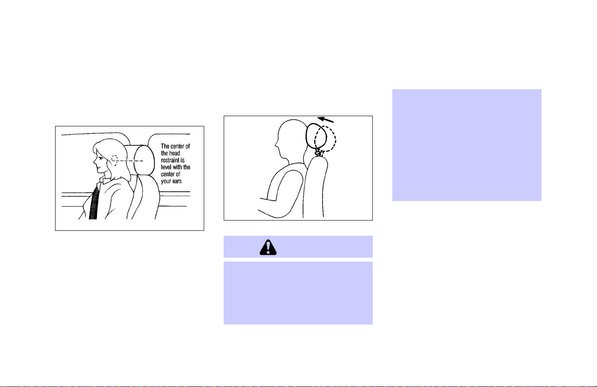
To raise the head restraint, simply pull it up.
To lower, push the lock knob and push the
head restraint down.
SIR0144
Adjust the head restraints so the center is level
with the center of your ears.
1-6
ACTIVE HEAD RESTRAINT
(Front seats)
WARNING
O
Always adjust the head restraints
properly as specified in the previous section. Failure to do so can
reduce theeffectivenessofthe active head restraint.
SIR0113
O
Active head restraints are designed to supplement other safety
systems. Always wear seat belts.
No system can prevent all injuries
in any accident.
O
Do not attach anything to the head
restraint stalks. Doing so could
impair active head restraint function.
The head restraint moves forward utilizing the
force that the seatback receives from the
occupant in a rear-end collision. The movement of the head restraint helps support the
occupant’s head by reducing its backward
movement and helping absorb some of the
forces that may lead to whiplash type injuries.
Active head restraints are effective for collisions at low to medium speeds in which it is
said that whiplash injury occurs most.
Page 12
SEATS, RESTRAINTS AND SUPPLEMENTAL AIR BAG SYSTEMS
Active head restraints operate only in certain
rear-end collisions. After the collision, the
head restraints return to their original positions.
Properly adjust the active head restraints as
described in the previous section.
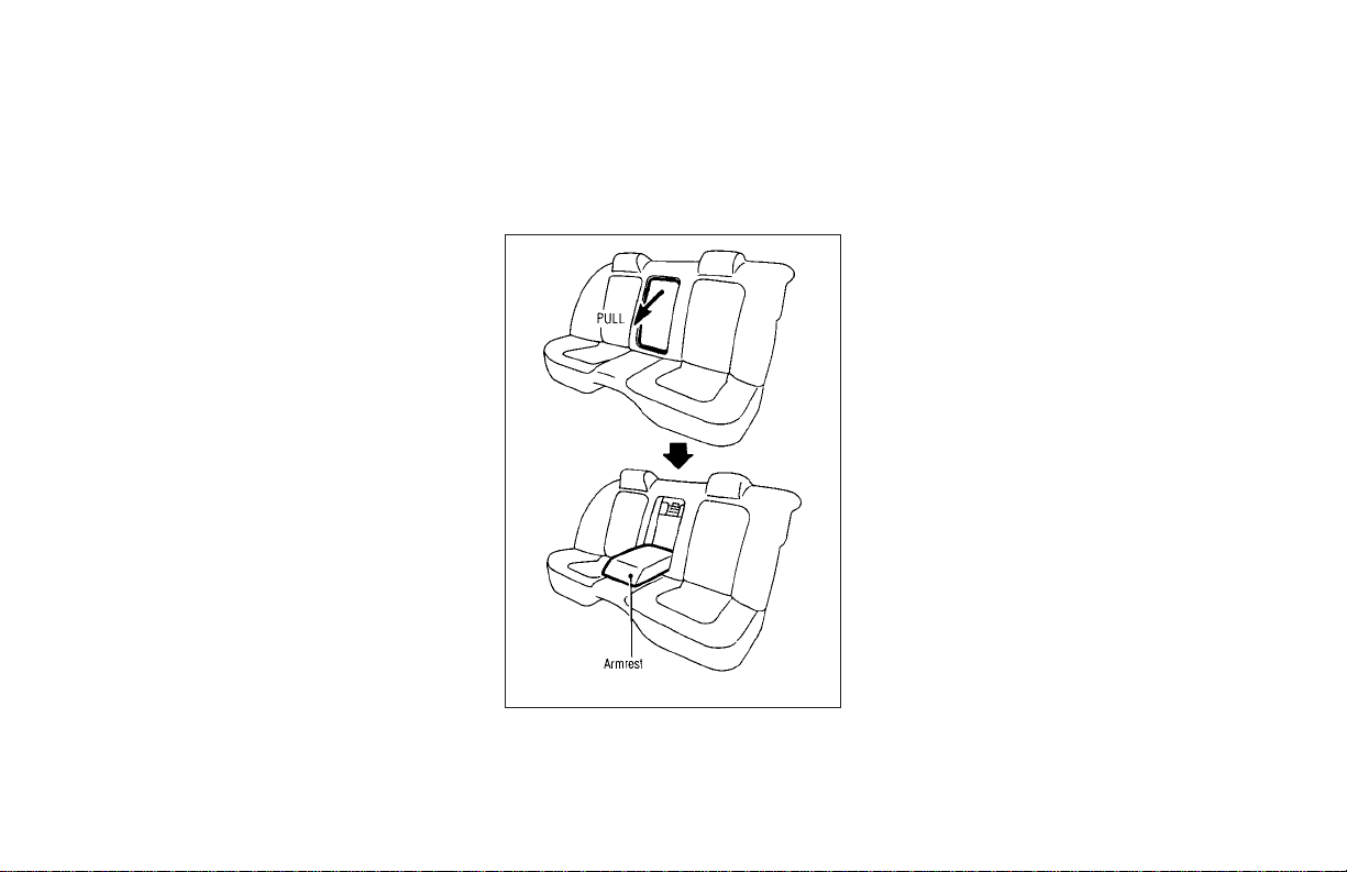
ARMREST
SIR0067
Pull the armrest forward until it is horizontal.
SUPPLEMENTAL RESTRAINT
SYSTEM
PRECAUTIONS ON SUPPLEMENTAL RESTRAINT SYSTEM
This Supplemental Restraint System (SRS)
section contains important information concerning the driver and passenger supplemental front air bags and supplemental side air
bags and pre-tensioner seat belt.
Supplemental front air bag system: This
system can help cushion the impact force to
the face and chest of the driver and front
passenger in certain frontal collisions.
Supplemental side air bag system: This
system can help cushion the impact force to
the head and the chest area of the driver and
front passenger in certain side impact collisions. The supplemental side air bag is
designed to inflate on the side where the
vehicle is impacted.
These supplemental restraint systems are de-
1-7
Page 13
SEATS, RESTRAINTS AND SUPPLEMENTAL AIR BAG SYSTEMS
signed to supplement the crash protection
provided by the driver and front passenger
seat belts and are not a substitute for them.
Seat belts should always be correctly worn
and the driver and front passenger seated a
suitable distance away from the steering
wheel, instrument panel and front door finishers. (See “Seat belts” later in this section for
instructions and precautions on seat belt
usage.)
After turning the ignition key to the ON
position, the supplemental air bag
warning light illuminates. The supplemental airbagwarninglight will turn off
afterabout 7secondsif thesystemis operational.
WARNING
O
The supplemental front air bags
ordinarily will not inflate in the
event of a side impact, rear im-
pact, roll over, or lower severity
frontal collision. Always wear
your seat belts to help reduce the
risk or severity of injury in various
kinds of accidents.
SIR0092
1-8
Page 14
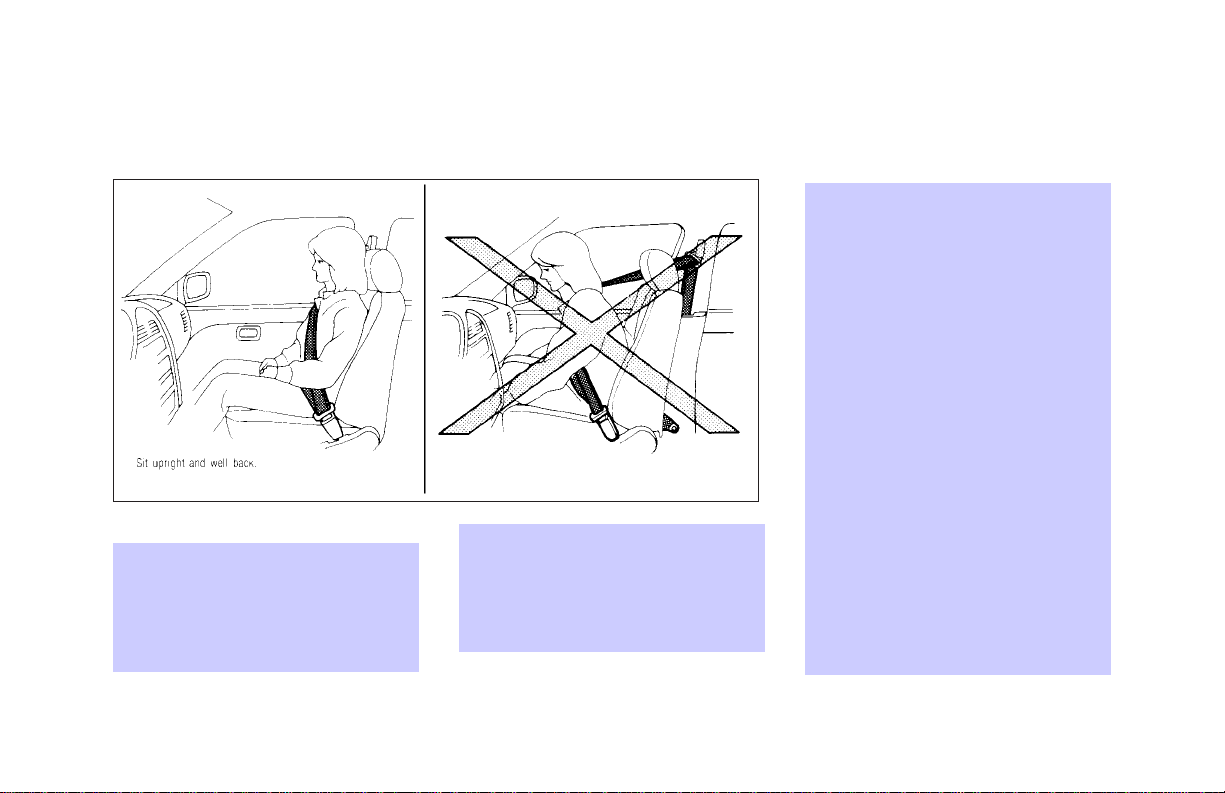
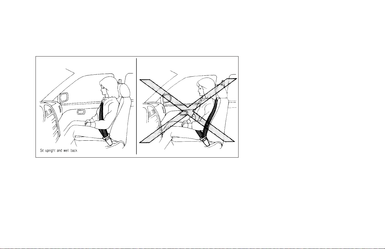
O
Theseatbelts and the supplemental front air bags are most effectivewhenyouare sitting well back
and upright in the seat. Front air
bags inflate with great force.
SEATS, RESTRAINTS AND SUPPLEMENTAL AIR BAG SYSTEMS
serious or fatal injuries from the
supplemental front air bag if you
are up against it when it inflates.
Always sit back against the seatback and as far away as practical
from the steering wheel or instrument panel. Always use the seat
belts.
O
The driver and front passenger
seat belt buckles are equipped
with sensors that detect if the
seat belts are fastened. The air
SIR0093
If you are unrestrained, leaning
forward, sitting sideways or out of
position in any way, you are at
greater risk of injury or death in a
crash. You may also receive
bag system monitors the severity
of a collision and then inflates the
air bags based on belt usage.
Failure to properly wear seat
belts can increase the risk or
severity of injury in an accident.
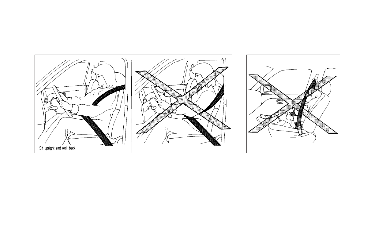
O
Keep hands on the outside of the
steering wheel. Placing them in-
1-9
Page 15
SEATS, RESTRAINTS AND SUPPLEMENTAL AIR BAG SYSTEMS
side the steering wheel rim could
increase the risk that they are
injured when the supplemental
front air bag inflates.
SIR0007 SIR0008
SIR0006
1-10
Page 16
SEATS, RESTRAINTS AND SUPPLEMENTAL AIR BAG SYSTEMS
SIR0009 SIR0010 SIR0011
1-11
Page 17
SEATS, RESTRAINTS AND SUPPLEMENTAL AIR BAG SYSTEMS
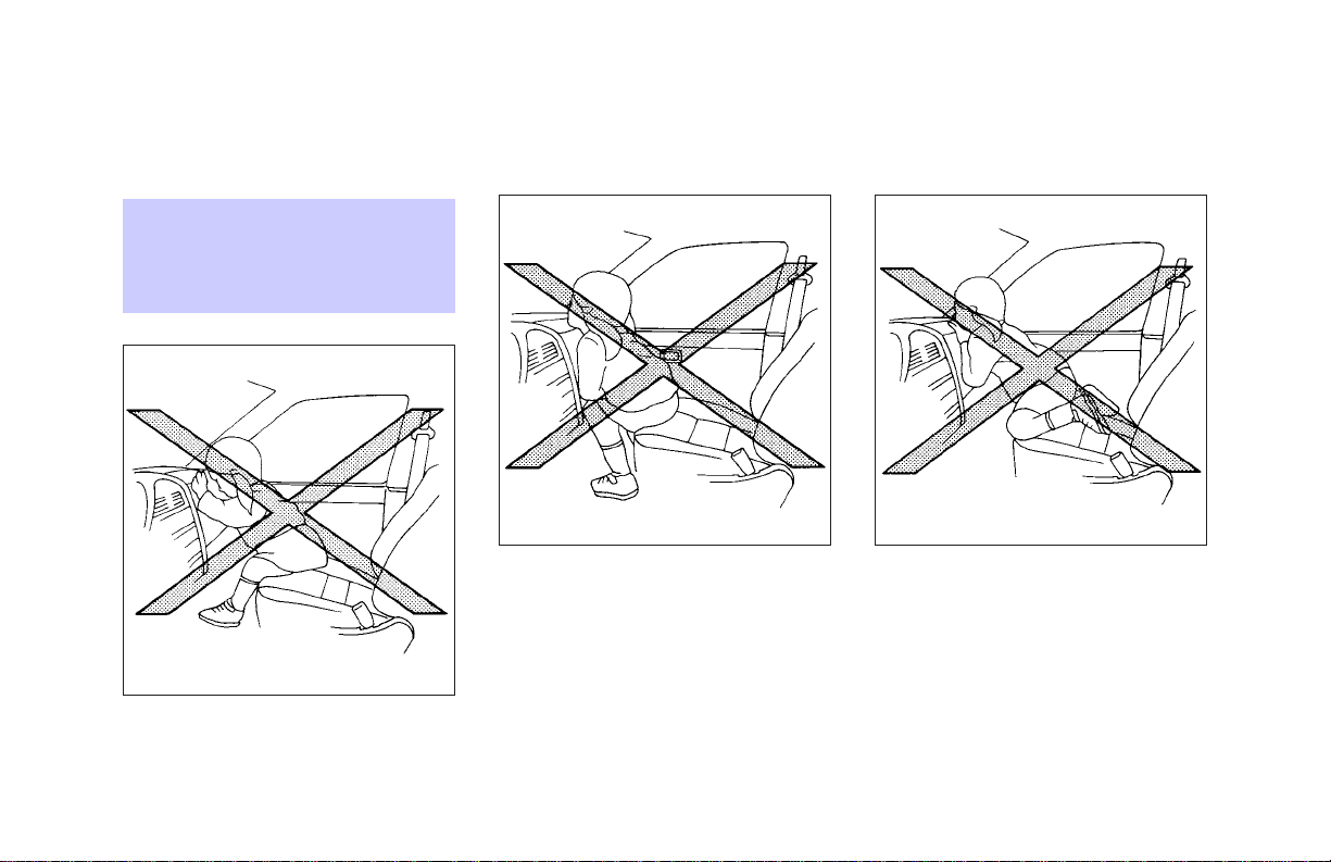
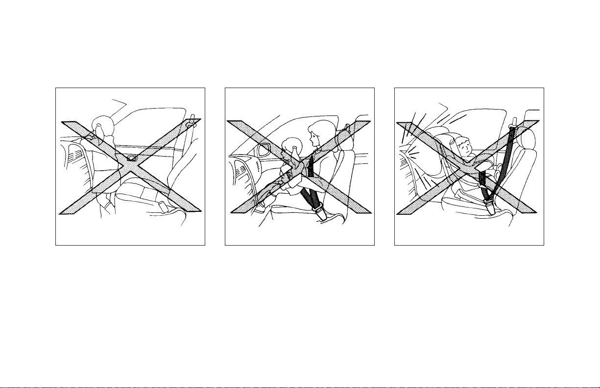
WARNING
O
Never let children ride unrestrained or extend their hands or
face out of the window. Do not attempt to hold them in your lap or
arms. Some examples of dangerous riding positions are shown in
the previous illustrations.
O
Children may be severely injured
or killed when the supplemental
front air bag or supplemental side
air bag inflates if they are not
properly restrained.
O
Also never install a rear facing
child restraint in the front seat.
An inflating supplemental front
air bag could seriously injure or
kill your child. For additional
1-12
information, see “Child restraints” later in this section.
WARNING
Supplemental side air bag
O
The supplemental side air bag
ordinarily will not inflate in the
SIR0059
Page 18
SEATS, RESTRAINTS AND SUPPLEMENTAL AIR BAG SYSTEMS
SIR0094
event lower severity side collision. Always wear your seat belts
to help reduce the risk or severity
of injury in various kinds of
accidents.
SIR0121
SIR0122
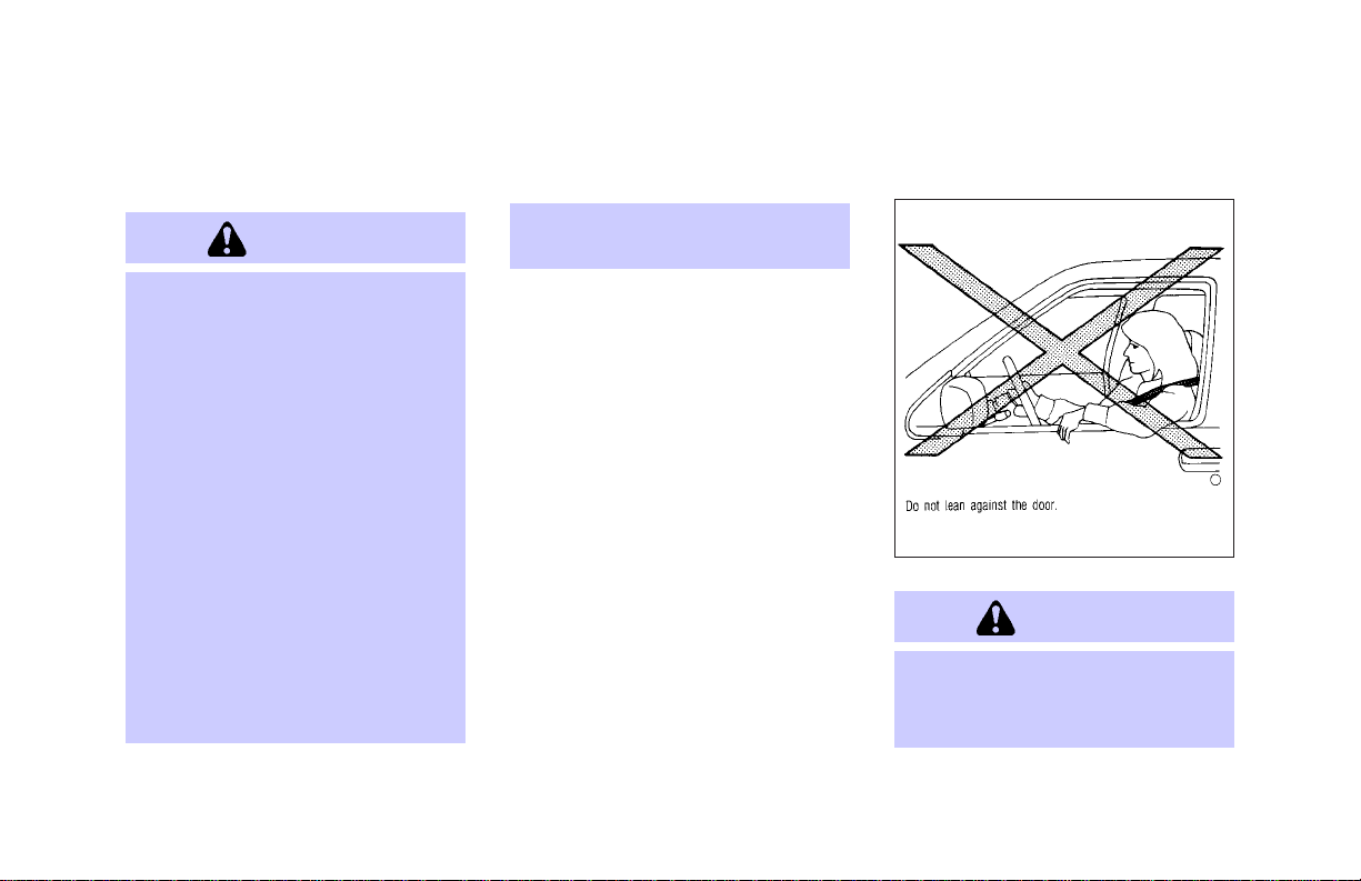
O
Theseatbelts and the supplemental side air bag are most effective
whenyouaresitting well back and
upright in the seat. The side air
bag inflates with great force. Do
not allow anyone to place their
hand, leg or face near the side air
bag on the side of the seatback of
thefront seat.Donot allowanyone
sitting in the front seat to extend
their hand out of the window or
lean against the door. Some examples of dangerous riding positions are shown in the previous
illustrations.
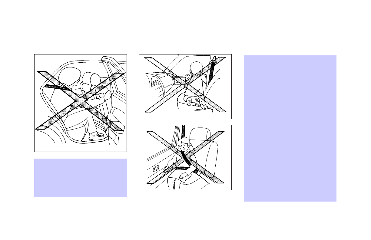
O
When sitting in the rear seat, do
not hold onto the seatback of the
front seat. If the supplemental
side air bag inflates, you may be
seriously injured. Be es-
1-13
Page 19
SEATS, RESTRAINTS AND SUPPLEMENTAL AIR BAG SYSTEMS
pecially careful with children,
who should always be properly
restrained.
O
Do not use seat covers on the
front seatbacks. They may interfere with supplemental side air
bag inflation.
SIR0137A
1-14
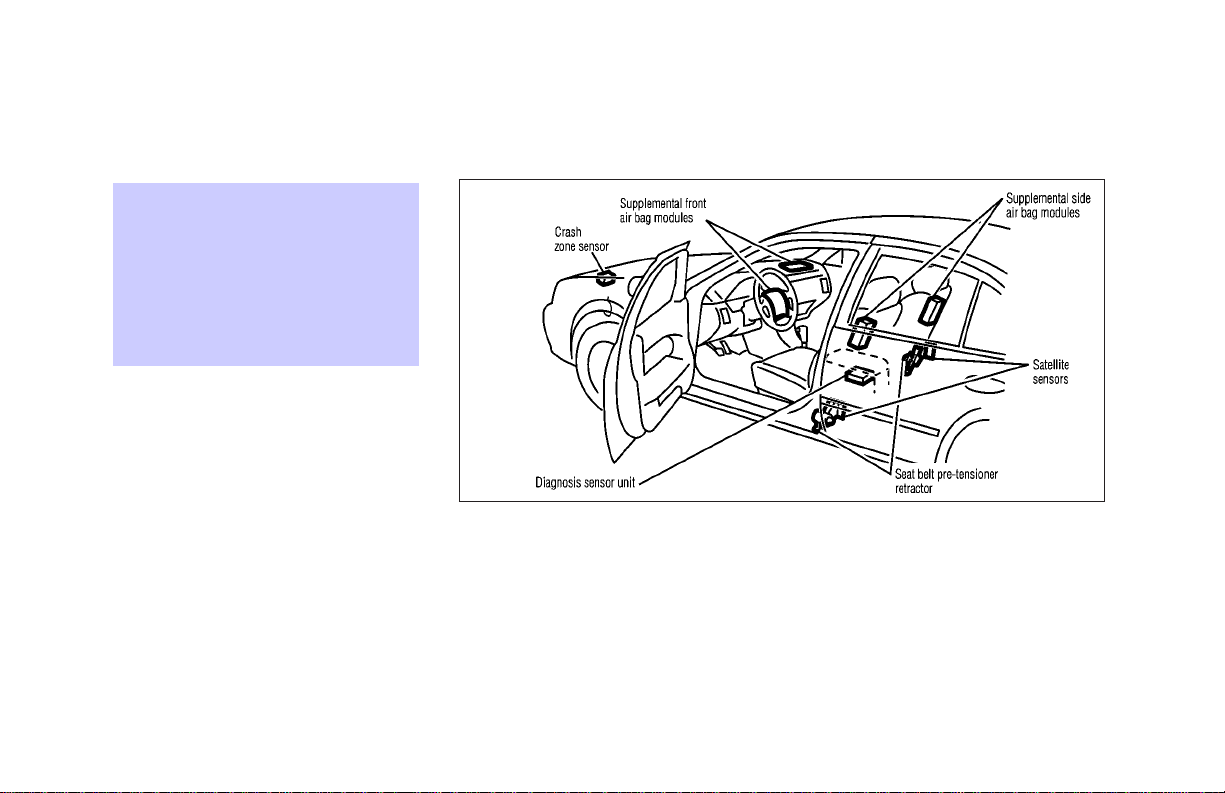
Supplemental front air bag system
The driver supplemental air bag is located in
the center of the steering wheel; the front
passenger supplemental air bag is mounted in
the dashboard above the glove box. These
systems are designed to meet optional certi-
fication requirements under U.S. regulations.
They are also permitted in Canada. The
optional certification allows front air bags to
be designed to inflate somewhat less forcefully than previously. However, all of the
information, cautions and warnings in
this manual still apply and must be
followed. The front air bags are designed to
Page 20

SEATS, RESTRAINTS AND SUPPLEMENTAL AIR BAG SYSTEMS
inflate in higher severity frontal collisions,
although they may inflate if the forces in
another type of collision are similar to those of
a higher severity frontal impact. They may not
inflate in certain frontal collisions. Vehicle
damage (or lack of it) is not always an
indication of proper supplemental air bag
operation.
The supplemental air bag system has dual
stage inflators for both the driver and passenger air bags. The system monitors information
from the crash zone sensor, the diagnosis
sensor unit and seat belt buckle sensors that
detect if the seat belts are fastened, inflator
operation is based on the severity of a
collision and whether the seat belts are being
used.
When the supplemental front air bag inflates,
a fairly loud noise may be heard, followed by
release of smoke. This smoke is not harmful
and does not indicate a fire. Care should be
taken not to inhale it, as it may cause irritation
and choking. Those with a history of a
breathing condition should get fresh air
promptly.
Supplemental front air bags, along with the
use of seat belts, help to cushion the impact
force on the face and chest of the front
occupants. They can help save lives and
reduce serious injuries. However, an inflating
front air bag may cause facial abrasions or
other injuries. Front air bags do not provide
restraint to the lower body.
The seat belts should be correctly worn and
the driver and passenger seated upright as far
as practical away from the steering wheel or
dash board. The supplemental front air bags
inflate quickly in order to help protect the front
occupants. Because of this, the force of the
front air bag inflating can increase the risk of
injury if the occupant is too close to, or is
against, the air bag module during inflation.
The air bag will deflate quickly after the
collision is over.
After turning the ignition key to the ON
position, the supplemental air bag
warning light illuminates. The supplemental airbagwarninglight will turn off
afterabout 7secondsif thesystemis operational.
WARNING
O
Do not place any objects on the
steering wheel pad or on the instrumentpanel.Also, do not place
any objects between any occupant
and the steering wheel or instrument panel. Such objects may become dangerous projectiles and
cause injury if the supplemental
front air bag inflates.
O
Right after inflation, several air
bag system components will be
hot. Do not touch them; you may
1-15
Page 21

SEATS, RESTRAINTS AND SUPPLEMENTAL AIR BAG SYSTEMS
severely burn yourself.
O
No unauthorized changes should
be made to any components or
wiring of the supplemental front
air bag system. This is to prevent
accidental inflation of the air bag
or damage to the air bag system.
O
Do not make unauthorized
changes to your vehicle’s electrical system, suspension system or
front end structure. This could
affect proper operation of the
supplemental air bag system.
O
Tampering with the supplemental
front air bag system may result in
serious personal injury. Tampering includes changes to the steering wheel and the instrument
panel assembly by placing material over the steering wheel pad
1-16
and above the dashboard, or by
installing additional trim material
around the air bag system.
O
Work around and on the supplemental front air bag system
should be done by an authorized
INFINITI retailer. Installation of
electrical equipment should also
be done by an authorized INFINITI
retailer. The SRS wiring harnesses* should not be modified
or disconnected. Unauthorized
electrical test equipment and
probing devices should not be
used on the air bag system.
* The SRS wiring harnesses are
covered with yellow insulation either just before the harness connectors or over the complete harness for easy identification.
O
A cracked windshield should be
replaced immediately by a qualified repair facility. A cracked
windshield could affect inflation
of the supplemental air bag system.
When selling your vehicle, we request that you
inform the buyer about the supplemental front
air bag system and guide the buyer to the
appropriate sections in this Owner’s Manual.
Supplemental side air bag system
SIR0129
Page 22

SEATS, RESTRAINTS AND SUPPLEMENTAL AIR BAG SYSTEMS
The supplemental side air bags are located in
the outside of the seatback of the front seats.
The supplemental side air bag (on the driver
or front passenger seat) is designed to inflate
in higher severity side collisions, although it
may inflate if the forces in another type of
collision are similar to those of a higher
severity side impact. It is designed to inflate
on the side where the vehicle is impacted. It
may not inflate in certain side collisions.
Vehicle damage (or lack of it) is not always an
indication of proper supplemental side air bag
operation.
When the supplemental side air bag inflates, a
fairly loud noise may be heard, followed by
release of smoke. This smoke is not harmful
and does not indicate a fire. Care should be
taken not to inhale it, as it may cause irritation
and choking. Those with a history of a
breathing condition should get fresh air
promptly.
Supplemental side air bags, along with the
use of seat belts, help to cushion the impact
force on the head and the chest of the front
occupants. They can help save lives and
reduce serious injuries. However, an inflating
side air bag may cause abrasions or other
injuries. Supplemental side air bags do not
provide restraint to the lower body.
The seat belts should be correctly worn and
the driver and passenger seated upright as far
as practical away from supplemental side air
bag. The side air bags inflate quickly in order
to help protect the front occupants. Because of
this, the force of the side air bag inflating can
increase the risk of injury if the occupant is
too close to, or is against, the side air bag
module during inflation. The side air bag will
deflate quickly after the collision is over.
After turning the ignition key to the ON
position, the supplemental air bag
warning light illuminates. The supplemental airbagwarninglight will turn off
afterabout 7secondsif thesystemis operational.
WARNING
O
Do not place any objects near the
seatback of the front seats. Also,
do not place any objects (an umbrella, bag, etc.) between the
front door finisher and the front
seat. Such objects may become
dangerous projectiles and cause
injury if the supplemental side air
bag inflates.
O
Right after inflation, several
supplemental side air bag system
components will be hot. Do not
touch them; you may severely
burn yourself.
O
No unauthorized changes should
be made to any components or
wiring of the supplemental side
1-17
Page 23

SEATS, RESTRAINTS AND SUPPLEMENTAL AIR BAG SYSTEMS
air bag system. This is to prevent
accidental inflation of the side air
bag or damage to the side air bag
system.
O
Do not make unauthorized
changes to your vehicle’s electrical system, suspension system or
side panel. This could affect
proper operation of the side air
bag system.
O
Tampering with the supplemental
side air bag system may result in
serious personal injury. For example, do not change the front
seat assembly by placing material near the seatback of the front
seat, or by installing additional
trim material, such as seat covers, around the side air bag
system.
1-18
O
Work around and on the supplemental side air bag system
should be done by an authorized
INFINITI retailer. Installation of
electrical equipment should also
be done by an authorized INFINITI
retailer.
The SRS wiring harnesses*
should not be modified or disconnected. Unauthorized electrical
test equipment and probing devices should not be used on the
side air bag system.
* The SRS wiring harnesses are
covered with yellow insulation either just before the harness connectors or over the complete harness for easy identification.
When selling your vehicle, we request that you
inform the buyer about the supplemental side
air bag system and guide the buyer to the
appropriate sections in this Owner’s Manual.
Pre-tensioner seat belt system
(For front seats)
WARNING
O
Thepre-tensionerseatbelt cannot
be reused after activation. It must
be replaced together with the retractor as a unit.
O
If the vehicle becomes involved in
a frontal collision but the pretensioner is not activated, be sure
to have the pre-tensioner system
checked and, if necessary, replaced by your INFINITI retailer.
O
No unauthorized changes should
be made to any components or
wiring of the pre-tensioner seat
Page 24

SEATS, RESTRAINTS AND SUPPLEMENTAL AIR BAG SYSTEMS
belt system. This is to prevent
accidental activation of the pretensioner seat belt or damage to
the pre-tensioner seat belt operation. Tampering with the pretensioner seat belt system may
result in serious personal injury.
O
Work around and on the pretensioner system should be done
by an authorized INFINITI retailer. Installation of electrical
equipment should also be done
by an authorized INFINITI retailer. Unauthorized electrical
test equipment and probing devices should not be used on the
pre-tensioner seat belt system.
O
If you need to dispose of the
pre-tensioner or scrap the vehicle, contact an authorized
INFINITI retailer. Correct pretensioner disposal procedures
are set forth in the appropriate
INFINITI Service Manual. Incorrect disposal procedures could
cause personal injury.
The front seat pre-tensioner seat belt system
activates in conjunction with the supplemental
front air bag. Working with the seat belt
retractor, it helps tighten the seat belt the
instant the vehicle becomes involved in certain types of collisions, thereby restraining
seat occupants.
The pre-tensioner is encased with the seat
belt’s retractor. These seat belts are used the
same as conventional seat belts.
When the pre-tensioner seat belt activates,
smoke is released and a loud noise may be
heard. The smoke is not harmful, but care
should be taken not to inhale it as it may
cause irritation and choking. Those with a
history of a breathing condition should get
fresh air promptly.
If any abnormality occurs in the pre-tensioner
system, the supplemental air bag warning
light
mittently or will turn on for 7 seconds and
remain on after the ignition key has been
turned to the ON or START position. In this
case, the pre-tensioner seat belt may not
function properly.
When selling your vehicle, we request that you
inform the buyer about the pre-tensioner seat
belt system and guide the buyer to the
appropriate sections in this Owner’s Manual.
will not come on, will flash inter-
1-19
Page 25
SEATS, RESTRAINTS AND SUPPLEMENTAL AIR BAG SYSTEMS
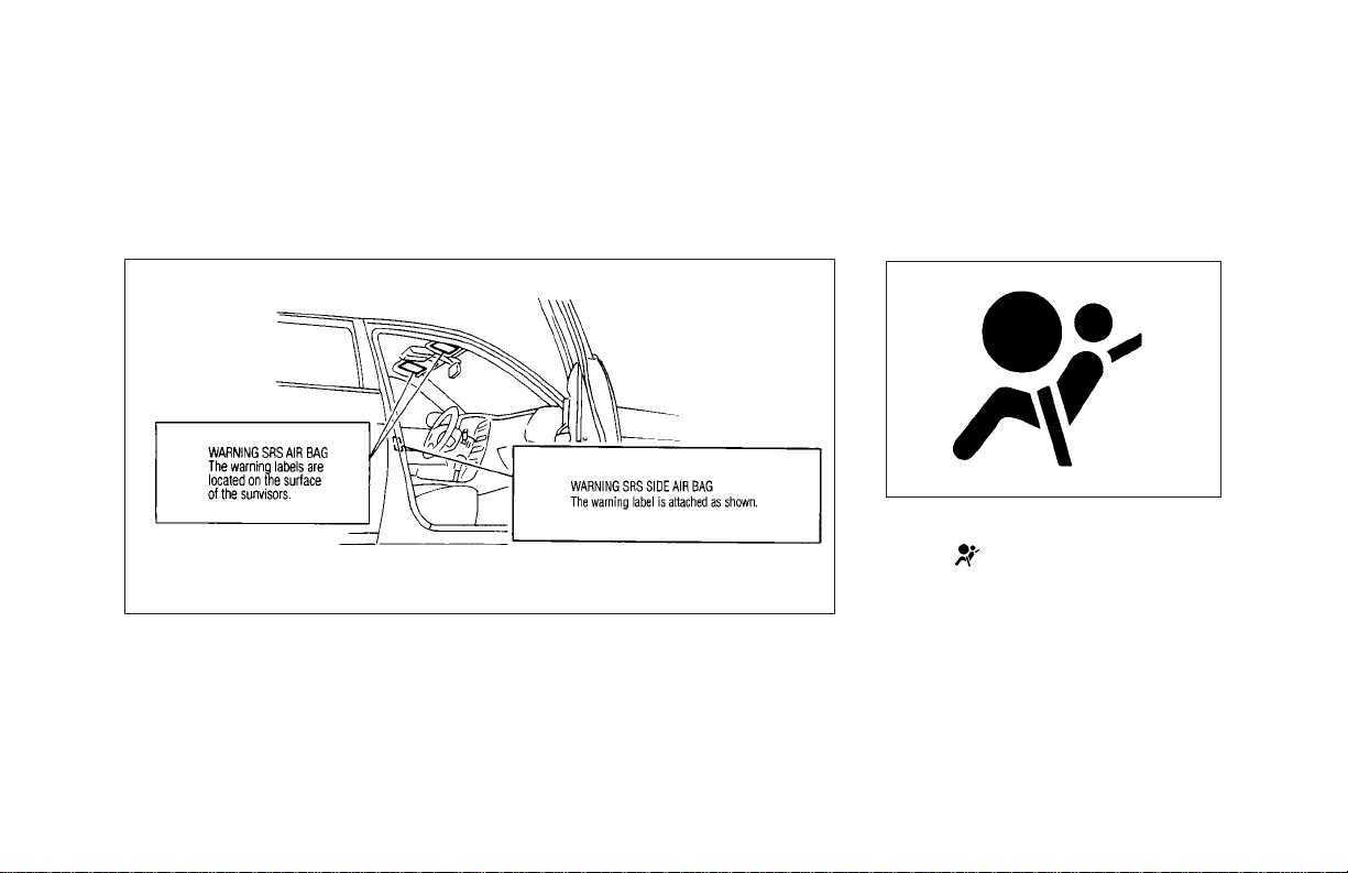
SUPPLEMENTAL AIR BAG
WARNING LABELS
Warning labels about the supplemental air
bag system are placed in the vehicle as shown
in the illustration.
1-20
SIR0096D
SUPPLEMENTAL AIR BAG
WARNING LIGHT
SIR0132
The supplemental air bag warning light, displaying
tors the circuits of the supplemental front air
bag system, supplemental side air bag system, and pre-tensioner seat belt. The circuits
monitored by the air bag warning light are the
diagnosis sensor unit, satellite sensors, front
air bag modules, side air bag modules and all
related wiring, and pre-tensioner seat belt.
After turning the ignition key to the ON
in the instrument panel, moni-
Page 26

SEATS, RESTRAINTS AND SUPPLEMENTAL AIR BAG SYSTEMS
position, the supplemental air bag warning
light illuminates. The supplemental air bag
warning light will turn off after about 7
seconds if the system is operational.
If any of the following conditions occur, the
supplemental front air bag system, supplemental side air bag system, and pre-tensioner
seat belt need servicing:
O The supplemental air bag warning light
remains on after approximately 7 seconds.
O The supplemental air bag warning light
flashes intermittently.
O The supplemental air bag warning light
does not come on at all.
Under these conditions, the supplemental
front air bags, supplemental side air bags
and/or pre-tensioner seat belt may not operate
properly. They must be checked and repaired.
Take your vehicle to the nearest authorized
INFINITI retailer.
WARNING
If the supplemental air bag warning
light is on, it could mean that the
supplemental front air bag system,
supplemental side air bag system
and/or pre-tensioner seat belt will
not operate in an accident.
Repair and replacement procedure
The supplemental front air bags, supplemental
side air bags and pre-tensioner seat belt are
designed to inflate on a one-time-only basis.
As a reminder, unless it is damaged, the
supplemental air bag warning light will remain
illuminated after inflation has occurred. Repair
and replacement of these systems should be
done only by authorized INFINITI retailers.
When maintenance work is required on the
vehicle, the supplemental front air bags,
supplemental side air bags, related parts and
pre-tensioner seat belt should be pointed out
to the person conducting the maintenance.
The ignition key should always be in the
LOCK position when working under the hood
or inside the vehicle.
WARNING
O
Once the supplemental front air
bag, supplemental side air bag
and/or pre-tensioner seat belt
haveactivated, theairbag module
will not function again and must
bereplaced,additionally,if any of
the supplemental air bags inflate,
the pre-tensioner seat belts must
also be replaced. The module
should be replaced by an authorized INFINITI retailer. The
supplementalfront airbagmodule
orsupplementalside air bag mod-
1-21
Page 27

SEATS, RESTRAINTS AND SUPPLEMENTAL AIR BAG SYSTEMS
ule cannot be repaired.
O
The supplemental front air bag
system, supplemental side air
bag system and pre-tensioner
seat belt should be inspected by
an authorized INFINITI retailer if
there is any damage to the front
end or side portion of the vehicle.
O
If you need to dispose of these
supplemental systems or scrap
the vehicle, contact an authorized
INFINITI retailer.
Correct disposal procedures are
set forth in the appropriate
INFINITI Service Manual. Incorrect disposal procedures could
cause personal injury.
1-22
SEAT BELTS
PRECAUTIONS ON SEAT BELT
USAGE
Your chances of being injured or killed in an
accident and/or the severity of injury may be
greatly reduced if you are wearing your seat
belt and it is properly adjusted. INFINITI
strongly encourages you and all of your
passengers to buckle up every time you drive,
even if your seating position includes a
supplemental air bag.
Most states, provinces or territories require that seatbeltsbewornat all times
when a vehicle is being driven.
Page 28
SEATS, RESTRAINTS AND SUPPLEMENTAL AIR BAG SYSTEMS
SIR0102
1-23
Page 29
SEATS, RESTRAINTS AND SUPPLEMENTAL AIR BAG SYSTEMS
SIR0125 SIR0016
1-24
Page 30
SEATS, RESTRAINTS AND SUPPLEMENTAL AIR BAG SYSTEMS
SIR0014
WARNING
O
Every person who drives or rides
in this vehicle should use a seat
belt at all times. Children should
be properly restrained and, if appropriate, in a child restraint.
O
The belt should be properly adjusted to a snug fit. Failure to do
so may reduce the effectiveness
of the entire restraint system and
increase the chance or severity of
injury in an accident. Serious injury or death can occur if the seat
belt is not worn properly.
O
Always route the shoulder belt
over your shoulder and across
your chest. Never run the belt
behind your back, under your arm
or across your neck. The belt
should be away from your face
and neck, but not falling off your
shoulder.
O
Position the lap belt as low and
snug as possible around the hips,
not the waist. A lap belt worn too
high could increase the risk of
internal injuries in an accident.
O
Be sure the seat belt tongue is
securely fastened to the proper
buckle.
O
Do not wear the belt inside out or
twisted. Doing so may reduce its
effectiveness.
O
Do not allow more than one person to use the same belt.
O
Never carry more people in the
vehicle than there are seat belts.
1-25
Page 31

SEATS, RESTRAINTS AND SUPPLEMENTAL AIR BAG SYSTEMS
O
If the seat belt warning light
glows continuously while the ignition is turned ON with all doors
closed and all seat belts fastened, it may indicate a malfunction in the system. Have the system checked by your INFINITI
retailer.
O
Once the pre-tensioner seat belt
has activated, it cannot be reused
and must be replaced together
with the retractor. See your
INFINITI retailer.
O
Removal and installation of the
pre-tensioner seat belt system
components should be done by an
authorized INFINITI retailer.
O
All seat belt assemblies including
retractors and attaching hardware
should be inspected after any col-
1-26
lision by your INFINITI retailer.
INFINITI recommends that all
seat belt assemblies in use during a collision be replaced unless
the collision was minor and the
belts show no damage and continue to operate properly. Seat
belt assemblies not in use during
a collision should also be inspected and replaced if either
damage or improper operation is
noted.
O
All child restraints and attaching
hardware should be inspected after any collision. Always follow
the restraint manufacturer’s inspection instructions and replacement recommendations. The
child restraints should be replaced if they are damaged.
CHILD SAFETY
Children need adults to help protect
them. They need to be properly restrained.
The proper restraint depends on the child’s
size. Generally, infants [up to about 1 year and
less than 20 lb (9 kg)] should be placed in
rear facing child restraints. Front facing child
restraints are available for children who outgrow rear facing child restraints.
WARNING
Infants and children need special
protection. The vehicle’s seat belts
may not fit them properly. The shoulder belt may come too close to the
face or neck. The lap belt may not fit
over their small hip bones. In an accident, an improperly fitting seatbelt
Page 32

SEATS, RESTRAINTS AND SUPPLEMENTAL AIR BAG SYSTEMS
could cause serious or fatal injury.
Always use appropriate child restraints.
All US states and provinces of Canada require
the use of approved child restraints for infants
and small children. (See “Child restraints”
later in this section.)
In addition, there are many types of child
restraints available for larger children which
should be used for maximum protection.
INFINITI recommends that all preteens
and children be restrained in the rear
seat if possible. According to accident
statistics, children are safer when properly restrained in the rear seat than in
the front seat. This is especially important because your vehicle has a supplemental restraint system (air bag system) for the front passenger. (See
“Supplemental restraint system” ear-
lier in this section for precautions.)
Infants and small children
INFINITI recommends that infants and small
children be placed in child restraints that
comply with Federal Motor Vehicle Safety
Standards or Canadian Motor Vehicle Safety
Standards. You should choose a child restraint that fits your vehicle and always follow
the manufacturer’s instructions for installation
and use.
Larger children
Children who are too large for child restraints
should be seated and restrained by the seat
belts which are provided.
If the child’s seating position has a shoulder
belt that fits close to the face or neck, the use
of a booster seat (commercially available) may
help overcome this. The booster seat should
raise the child so that the shoulder belt is
properly positioned across the top, middle
portion of the shoulder and the lap belt is low
on the hips. The booster seat should fit the
vehicle seat and have a label certifying that it
complies with Federal Motor Vehicle Safety
Standards or Canadian Motor Vehicle Safety
Standards. Once the child has grown so the
shoulder belt is no longer on or near the face
and neck, use the shoulder belt without the
booster seat.
WARNING
Never let a child stand or kneel on
any seat and do not allow a child in
the cargo areas while the vehicle is
moving. The child could be seriously
injured or killed in an accident or a
sudden stop.
PREGNANT WOMEN
INFINITI recommends that pregnant women
use seat belts. The seat belt should be worn
snug, and always position the lap belt as low
1-27
Page 33

SEATS, RESTRAINTS AND SUPPLEMENTAL AIR BAG SYSTEMS
as possible around the hips, not the waist.
Place the shoulder belt over your shoulder
and across your chest. Never run the
lap/shoulder belt over your abdominal area.
Contact your doctor for specific recommendations.
INJURED PERSONS
INFINITI recommends that injured persons
use seat belts, depending on the injury.Check
with your doctor for specific recommendations.
THREE-POINT TYPE SEAT BELT
WITH RETRACTOR
WARNING
O
Every person who drives or rides
in this vehicle should use a seat
belt at all times.
1-28
O
Do not ride in a moving vehicle
when the seatback is reclined.
This can be dangerous. The
shoulder belt will not be against
your body. In an accident you
could be thrown into it and receive neck or other serious injuries. You could also slide under
the lap belt and receive serious
internal injuries.
O
For most effective protection
when the vehicle is in motion, the
seat should be upright. Always sit
well back in the seat and adjust
the seat belt properly.
Fastening the seat belts
1. Adjust the seat.
SIR0126
Page 34

SEATS, RESTRAINTS AND SUPPLEMENTAL AIR BAG SYSTEMS
and allow you some freedom of movement in the seat.
SIR0127
SIR0019
2. Slowly pull the seat belt out of the retractor
and insert the tongue into the buckle until
it snaps.
The retractor is designed to lock during
a sudden stop or on impact. A slow pulling motion will permit the belt to move,
SIR0061
3. Position the lap belt portion low and
snug on the hips as shown.
4. Pull the shoulder belt portion toward the
retractor to take up extra slack.
The front passenger and rear seat belts have a
cinching mechanism for child restraint instal-
1-29
Page 35

SEATS, RESTRAINTS AND SUPPLEMENTAL AIR BAG SYSTEMS
lation. It is referred to as the automatic locking
mode.
When the cinching mechanism is activated the
seat belt cannot be withdrawn again until the
seat belt tongue is detached from the buckle
and fully retracted. For additional information,
see “Child restraints” later in this section.
The automatic locking mode should be
usedonlyforchild restraint installation.
During normal seat belt use by a passenger, the locking mode should not be
activated. If it is activated it may cause
uncomfortable seat belt tension.
WARNING
When fastening the seat belts, be
certainthat seatbacks arecompletely
secured in the latched position. If
they are not completely secured in
1-30
the right position, passengers may
be injured in an accident or sudden
stop.
Unfastening the seat belts
SIR0021
To unfasten the belt, press the button on the
buckle. The seat belt will automatically retract.
Checking seat belt operation
Your seat belt retractors are designed to lock
belt movement using two separate methods:
O when the belt is pulled quickly from the
retractor.
O when the vehicle slows down rapidly.
To increase your confidence in the belts,
check their operation as follows:
O grasp the shoulder belt and pull quickly
forward. The retractor should lock and
restrict further belt movement.
If the retractor does not lock during this check
or if you have any questions about belt
operation, see your INFINITI retailer.
Page 36

SEATS, RESTRAINTS AND SUPPLEMENTAL AIR BAG SYSTEMS
Shoulder belt height adjustment
(For front seats)
The shoulder belt anchor height should be
adjusted to the position best for you. (See
“Precautions on seat belt usage” earlier in this
section.)
SIR0116
The shoulder belt anchor height should be
adjusted to the position best suited for you.
(See “Precautions on seat belt usage” earlier
in this section.) To lower, push the release
button, and then move the shoulder belt
anchor to the desired position, so that the belt
passes over the shoulder. Release the adjustment button to lock the shoulder belt anchor
into position.
To raise, move the adjuster up to the desired
position without pushing the button.
WARNING
O
After adjustment, release the button and try to move the shoulder
belt anchor down to make sure it
is securely fixed in position.
O
The shoulder belt anchor height
should be adjusted to the position
best for you. Failure to do so may
reduce the effectiveness of the
entire restraint system and increase the chance or severity of
injury in an accident.
SEAT BELT EXTENDERS
If, because of body size or driving position, it
is not possible to properly fit the lap-shoulder
belt and fasten it, an extender is available
which is compatible with the installed seat
belts. The extender adds approximately 8
inches (200 mm) of length and may be used
for either the driver or front passenger seating
position. See your INFINITI retailer for assistance if the extender is required.
WARNING
O
Only INFINITI belt extenders,
made bythesamecompany which
made the original equipment
belts, should be used with
INFINITI belts.
O
Adults and children who can use
the standard seat belt should not
use an extender. Such unneces-
1-31
Page 37

SEATS, RESTRAINTS AND SUPPLEMENTAL AIR BAG SYSTEMS
sary use could result in serious
personal injury in the event of an
accident.
O
Never use seat belt extenders to
install child restraints. If the child
restraint is not secured properly,
the child could be seriously injured in a collision or a sudden
stop.
SEAT BELT MAINTENANCE
O Tocleanthe seatbeltwebbings, apply
a mild soap solution or any solution recommended for cleaning upholstery or carpets. Then brush the webbing, wipe it with
a cloth and allow it to dry in the shade. Do
not allow the seat belts to retract until they
are completely dry.
O If dirt builds up in the shoulder belt guide
of the seat belt anchors, the seat belts may
1-32
retract slowly. Wipe the shoulder belt
guide with a clean, dry cloth.
O Periodically check to see that the
seat belt and the metal components
such as buckles, tongues, retractors, flexible wires and anchors work properly. If
loose parts, deterioration, cuts or other
damage on the webbing is found, the entire
belt assembly should be replaced.
CHILD RESTRAINTS
PRECAUTIONS ON CHILD RESTRAINTS
WARNING
O
Infants and small children should
always be placed in an appropriate child restraint while riding in
the vehicle. Failure to use a child
restraint can result in serious in-
jury or death.
O
Infants and small children should
never be carried on your lap. It is
not possible for even the strongest adult to resist the forces of a
severe accident. The child could
be crushed between the adult and
parts of the vehicle. Also, do not
put the same seat belt around
both your child and yourself.
O
Never install a rear facing child
restraint in the front seat. An
inflating supplemental front air
bag could seriously injure or kill
your child. A rear facing child
restraint must only be used in the
rear seat.
O
INFINITI recommends that the
child restraint be installed in the
rear seat. According to accident
Page 38

SEATS, RESTRAINTS AND SUPPLEMENTAL AIR BAG SYSTEMS
statistics, children are safer when
properly restrained in the rear
seat than in the front seat.
O
An improperly installed child restraint could lead to serious injury or death in an accident.
In general, child restraints are designed to be
installed with the lap portion of a three-point
type seat belt. In addition, this vehicle is
equipped with a universal child restraint lower
anchor system, referred to as the LATCH
(Lower Anchors and Tether for CHildren)
system. Some child restraints include two
rigid or webbing-mounted attachments that
can be connected to these lower anchors. For
details, see “LATCH (Lower Anchors and
Tether for Children) System” later in this
section.
Child restraints for infants and children of
various sizes are offered by several manufac-
turers. When selecting any child restraint,
keep the following points in mind:
O choose only a restraint with a label certi-
fying that it complies with Federal Motor
Vehicle Safety Standard 213 or Canadian
Motor Vehicle Safety Standard 213.
O check the child restraint in your vehicle to
be sure it is compatible with the vehicle’s
seat and seat belt system.
O if the child restraint is compatible with
your vehicle, place your child in the child
restraint and check the various adjustments to be sure the child restraint is
compatible with your child. Always follow
all recommended procedures.
All US states and Canadian provinces
require that infants and small children
be restrained in approved child restraints at all times while the vehicle is
being operated.
WARNING
O
Improper use of a child restraint
can resultinincreasedinjuries for
both the infant or child and other
occupants in the vehicle.
O
Follow all of the child restraint
manufacturer’s instructions for
installation and use. When purchasing a child restraint, be sure
to select one which will fit your
child and vehicle. It may not be
possible to properly install some
types of child restraints in your
vehicle.
O
If the child restraint is not anchored properly, the risk of a
1-33
Page 39

SEATS, RESTRAINTS AND SUPPLEMENTAL AIR BAG SYSTEMS
child being injured in a collision
or a sudden stop greatly increases.
O
Adjustable seatbacks should be
positioned to fit the child restraint, but as upright as possible.
O
After attaching the child restraint,
test it before you place the child
in it. Tilt it from side to side. Try
to tug it forward and check to see
if the belt holds the restraint in
place. If the restraint is not secure, tighten the belt as necessary, or put the restraint in another seat and test it again.
O
For a front facing child restraint,
check to make sure the shoulder
belt does not go in front of the
child’s face or neck. If it does, put
1-34
the shoulder belt behind the child
restraint. If you must install a
front facing child restraint in the
front seat, see instructions later
in this section.
O
When your child restraint is not in
use, store it in the trunk or keep it
secured with a seat belt to prevent it from being thrown around
in case of a sudden stop or accident.
CAUTION
Remember that a child restraint left
in a closed vehicle can become very
hot. Check the seating surface and
buckles before placing your child in
the child restraint.
INSTALLATION ON REAR SEAT
CENTER OR OUTBOARD POSITIONS
Front facing
WARNING
O
The three-point belt on your vehicle is equipped with a locking
mode retractor which must be
used when installing a child restraint.
O
Failure to do so will result in the
child restraint not being properly
secured. It could tip over or otherwise be unsecured and cause
injury to the child in a sudden
stop or collision.
When you install a child restraint in a rear
outboard or center seat, follow these steps:
Page 40

SEATS, RESTRAINTS AND SUPPLEMENTAL AIR BAG SYSTEMS
SIR0117 SIR0118
1. Position the child restraint on the seat. The
direction of the child restraint depends on
the type of the child restraint and the size
of the child. Always follow the restraint
manufacturer’s instructions.
2. Route the seat belt tongue through the
child restraint and insert it into the buckle
until you hear and feel the latch engage.
Be sure to follow the child restraint manufacturer’s instructions for belt routing.
SIR0043
1-35
Page 41

SEATS, RESTRAINTS AND SUPPLEMENTAL AIR BAG SYSTEMS
SIR0039A SIR0062 SIR0042
3. Pull on the shoulder belt until all of the
belt is fully extended. At this time, the belt
retractor is in the automatic locking mode
(child restraint mode). It reverts back to
emergency locking mode when the belt is
fully retracted.
1-36
4. Allow the belt to retract. Pull up on the belt
to remove any slack in the belt.
5. Before placing the child in the child
restraint, use force to tilt the child restraint
from side to side, and tug it forward to
make sure that it is securely held in place.
6. Check that the retractor is in the automatic
locking mode by trying to pull more belt
out of the retractor. If you cannot pull any
Page 42

SEATS, RESTRAINTS AND SUPPLEMENTAL AIR BAG SYSTEMS
more belt webbing out of the retractor, the
belt is in the automatic locking mode.
7. Check to make sure that the child restraint
is properly secured prior to each use. If the
belt is not locked, repeat steps 3 through
6.
After the child restraint is removed and the
seat belt is allowed to wind back into the
retractor, the automatic locking mode (child
restraint mode) is canceled; the seat belt only
locks during a sudden stop or impact.
Rear facing
WARNING
O
The three-point belt on your vehicle is equipped with a locking
mode retractor which must be
used when installing a child
restraint.
O
Failure to do so will result in the
child restraint not being properly
secured. It could tip over or otherwise be unsecured and cause
injury to the child in a sudden
stop or collision.
When you install a child restraint in a rear
outboard or center seat, follow these steps:
SIR0119
SIR0120
1. Position the child restraint on the seat. The
direction of the child restraint depends on
the type of the child restraint and the size
of the child. Always follow the restraint
manufacturer’s instructions.
1-37
Page 43

SEATS, RESTRAINTS AND SUPPLEMENTAL AIR BAG SYSTEMS
SIR0046 SIR0045A SIR0047
2. Route the seat belt tongue through the
child restraint and insert it into the buckle
until you hear and feel the latch engage.
Be sure to follow the child restraint manufacturer’s instructions for belt routing.
1-38
3. Pull on the shoulder belt until all of the
belt is fully extended. At this time, the belt
retractor is in the automatic locking mode
(child restraint mode). It reverts back to
emergency locking mode when the belt is
fully retracted.
4. Allow the belt to retract. Pull up on the belt
to remove any slack in the belt.
Page 44

SEATS, RESTRAINTS AND SUPPLEMENTAL AIR BAG SYSTEMS
SIR0048
5. Before placing the child in the child
restraint, use force to tilt the child restraint
from side to side, and tug it forward to
make sure that it is securely held in place.
6. Check that the retractor is in the automatic
locking mode by trying to pull more belt
out of the retractor. If you cannot pull any
more belt webbing out of the retractor, the
belt is in the automatic locking mode.
7. Check to make sure that the child restraint
is properly secured prior to each use. If the
belt is not locked, repeat steps 3 through
6.
After the child restraint is removed and the
seat belt is allowed to wind back into the
retractor, the automatic locking mode (child
restraint mode) is canceled; the seat belt only
locks during a sudden stop or impact.
LATCH (LOWER ANCHOR AND
TETHER FOR CHILDREN) SYSTEM
SIR0143B
WARNING
O
Attach LATCH system compatible
child restraints only at the locations shown. If a child restraint is
not secured properly, your child
1-39
Page 45

SEATS, RESTRAINTS AND SUPPLEMENTAL AIR BAG SYSTEMS
could be seriously injured or
killed in an accident.
O
Do not secure a child restraint in
the center rear seating position
using the LATCH system anchors.
The child restraint will not be
secured properly.
O
The LATCH system anchors are
designed to withstand only those
loads imposed by correctly fitted
child restraints. Under no circumstance are they to be used for
adult seat belts or harnesses.
Some child restraints include two rigid or
webbing-mounted attachments that can be
connected to two anchors located at certain
seating positions in your vehicle. This system
is known as the LATCH (Lower Anchors and
Tether for CHildren) system. This system may
also be referred to as the ISOFIX or ISOFIX
1-40
compatible system. With this system, you do
not have to use a vehicle seat belt to secure
the child restraint. Your vehicle is equipped
with special anchor points that are used with
LATCH system compatible child restraints.
Check your child restraint for a label starting
that it is compatible with the LATCH system.
This information may also be in the child
restraint owner’s manual. If you have such a
child restraint, refer to the illustration for the
rear seating positions equipped with LATCH
system anchors which can be used to secure
the child restraint.
The LATCH system anchors are located at the
rear of the seat cushion near the seatback. A
label is attached to the seatback to help you
locate the LATCH system anchors.
Some child restraints may also require the use
of a top tether strap. See “Top tether strap
child restraint” later in this section for installation instructions.
When installing, carefully read and follow the
instructions in this manual and those supplied
with the child restraint.
When you install a LATCH system compatible
child restraint to the lower anchor attachments
in the rear seat, follow these steps:
WARNING
Inspect the lower anchors by inserting yourfingersintothe lower anchor
area and feeling to make sure there
are no obstructions over the LATCH
system anchors, such as seat belt
webbing or seat cushion material.
Thechild restraint willnot besecured
properlyif the LATCH systemanchors
are obstructed.
1. To install the LATCH system compatible
child restraint, insert the child restraint
Page 46

SEATS, RESTRAINTS AND SUPPLEMENTAL AIR BAG SYSTEMS
LATCH system attachments into the anchor points on the rear seat. If the child
restraint is equipped with a top tether, see
“Top tether child restraint” later in this
section for installation instructions.
2. After attaching the child restraint and
before placing the child in it, use force to
tilt the child restraint from side to side and
tug it forward to make sure that the child
restraint is securely held in place.
3. Check to make sure that the child restraint
is properly secured prior to each use.
TOP TETHER STRAP CHILD RESTRAINT
SIR0115
If your child restraint has a top tether strap, it
must be secured to the provided anchor point.
First, secure the child restraint with the rear
seat belt.
Remove the anchor cover from the anchor
point which is located directly behind the
child seat.
Secure the top tether strap to the anchor
bracket.
Keep the removed cover in a secured place to
prevent loss or damage.
WARNING
Thechildrestraint anchor point is designed to withstand only those loads
imposed by correctly fitted child restraints. Under no circumstance is it
to be used for adult seat belts or harnesses.
Anchor point locations
Anchor points are located on the rear parcel
shelf finisher.
If you have any questions when installing a topstrapchildrestrainton the rear
seat, consult your INFINITI retailer for
details.
1-41
Page 47

SEATS, RESTRAINTS AND SUPPLEMENTAL AIR BAG SYSTEMS
INSTALLATION ON FRONT
PASSENGER SEAT
WARNING
O
Never install a rear facing child
1-42
SIR0101
restraint in the front passenger
seat. Supplemental front air bags
inflatewithgreatforce. A rear facing child restraint could be struck
by the air bag in a crash and
could seriously injure or kill your
child.
O
INFINITI recommends that child
restraints be installed in the rear
seat. However, if you must install
a front facing child restraint in the
front passenger seat, move the
passenger seat to the rearmost
position.
O
A child restraint with a top tether
strap should not be used in the
front passenger seat.
O
The three-point belt in your vehicle is equipped with a locking
mode retractor which must be
used when installing a child
restraint.
Page 48

SEATS, RESTRAINTS AND SUPPLEMENTAL AIR BAG SYSTEMS
O
Failure to use the retractor’s locking mode will result in the child
restraint not being properly secured. The child restraint could
tip over or otherwise be unsecured and cause injury to the
child in a sudden stop or
collision.
Front facing
If you must install a child restraint in the front
seat, follow these steps:
SIR0103
1.
Position the child restraint on the front
passenger seat. It should be placed in a
front facing direction only. Move the
seat to the rearmost position. Always follow
the child restraint manufacturer’s instructions. Child restraints for infants must
be used in the rear facing direction
and therefore must not be used in the
front seat.
SIR0055
2. Route the seat belt tongue through the
child restraint and insert it into the buckle
1-43
Page 49

SEATS, RESTRAINTS AND SUPPLEMENTAL AIR BAG SYSTEMS
until you hear and feel the latch engage.
Be sure to follow the child restraint manufacturer’s instructions for belt routing.
SIR0053A
3. Pull on the shoulder belt until all of the
belt is fully extended. At this time, the belt
retractor is in the automatic locking mode
(child restraint mode). It reverts back to
1-44
emergency locking mode when the belt is
fully retracted.
SIR0056
4. Allow the belt to retract. Pull up on the belt
to remove any slack in the belt.
SIR0063
5. Before placing the child in the child
restraint, use force to tilt the child restraint
from side to side, and tug it forward to
make sure that it is securely held in place.
6. Check that the retractor is in the automatic
locking mode by trying to pull more belt
out of the retractor. If you cannot pull any
Page 50

SEATS, RESTRAINTS AND SUPPLEMENTAL AIR BAG SYSTEMS
more belt webbing out of the retractor, the
belt is in the automatic locking mode.
7. Check to make sure that the child restraint
is properly secured prior to each use. If the
lap belt is not locked, repeat steps 3
through 6.
After the child restraint is removed and the
seat belt is allowed to wind back into the
retractor, the automatic locking mode (child
restraint mode) is canceled; the seat belt only
locks during a sudden stop or impact.
1-45
Page 51

2 INSTRUMENTS AND CONTROLS
Instrument panel ......................................... 2-2
Meters and gauges...................................... 2-3
Speedometer and odometer................... 2-4
Tachometer............................................. 2-4
Engine coolant temperature gauge ........ 2-5
Fuel gauge.............................................. 2-5
Warning/indicator lights and audible
reminders..................................................... 2-7
Checking bulbs....................................... 2-7
Warning lights........................................ 2-8
Indicator lights..................................... 2-10
Audible reminders................................ 2-13
Security system......................................... 2-13
Vehicle security system ....................... 2-13
Infiniti Vehicle Immobilizer System...... 2-15
Windshield wiper and washer switch........ 2-16
Rear window and outside mirror (if so
equipped) defogger switch........................ 2-17
Headlight and turn signal switch............... 2-17
Xenon headlights.................................. 2-17
Headlight switch................................... 2-18
Turn signal switch................................ 2-21
Cornering light...................................... 2-21
Front fog light switch ................................ 2-21
Hazard warning flasher switch .................. 2-22
Horn........................................................... 2-22
Heated seats (if so equipped)................... 2-23
Heated steering switch (if so equipped)... 2-24
Traction control system (TCS) cancel
switch (if so equipped)........................ 2-24
Vehicle dynamic control off switch (if so
equipped)................................................... 2-24
Power outlet .............................................. 2-25
Cigarette lighter and ashtray..................... 2-25
Glasses case......................................... 2-26
Cup holder............................................ 2-27
Glove box............................................. 2-28
Console box.......................................... 2-28
Cargo net (if so equipped)................... 2-29
Windows.................................................... 2-29
Power windows.................................... 2-29
Sunroof (if so equipped)........................... 2-31
Page 52

Electric sunroof.................................... 2-31
Rear sun shade (if so equipped)............... 2-33
Clock.......................................................... 2-35
Adjusting the time................................ 2-35
Trip computer............................................ 2-35
Interior light............................................... 2-37
Ceiling................................................... 2-37
Personal light............................................. 2-38
Front..................................................... 2-39
Vanity mirror lights.................................... 2-39
Trunk light ................................................. 2-40
HomeLinkT Universal Transceiver (if so
equipped)................................................... 2-40
Programming HomeLinkT ................... 2-41
Programming HomeLinkT for Canadian
customers............................................. 2-42
Operating the HomeLinkT
Universal Transceiver........................... 2-42
Programming trouble diagnosis........... 2-42
Clearing the programmed
information........................................... 2-42
Rolling code programming .................. 2-43
Reprogramming a single HomeLinkT
button................................................... 2-43
If your vehicle is stolen........................ 2-44
Page 53

INSTRUMENTS AND CONTROLS
INSTRUMENT PANEL
2-2
1 Outside mirror remote control (P.3-18)
2 Headlight and turn signal switch
(P.2-17)/Front fog light switch (P.2-21)
3 Security indicator light (P.2-14)
4 Instrument brightness control switch
(P.2-19)
5 Meters/gauges (P.2-3)
6 Cruise control main/set switch (P.5-12)
7 Traction control (TCS) or Vehicle dynamic
control (VDC) OFF switch (if so equipped)
(P.2-24)
8 Windshield wiper/washer switch (P.2-16)
9 Center ventilator (P.4-2)
10 Audio system (P.4-7) and navigation con-
trol*
11 Clock (P.2-35)
12 Automatic air conditioner (P.4-3)
13 Navigation system*
14 Front passenger supplemental air bag
(P.1-7)
15 Side ventilator (P.4-2)
16 Cup holder (P.2-27)
SII0362
Page 54

INSTRUMENTS AND CONTROLS
17 Automatic drive position system cancel
switch (P.3-21)
18 Fuse box cover (P.8-21)
19 Hood release handle (P.3-10)
20 Heated steering switch (P.2-24)
21 Steering switch for audio control (P.4-25)
and trip computer (P.2-35)
22 Tilting steering wheel lock lever (P.3-15)
23 Driver supplemental air bag (P.1-7)
24 Ignition switch/steering lock (P.5-5)
25 Hazard warning flasher switch (P.2-22)
26 Rear sun shade control switch (P.2-34)
27 Heated seat switch (if so equipped)
(P.2-33)
28 Cigarette lighter (P.2-25)
29 Ashtray (P.2-25)
30 Rear window and outside door mirror
defogger switch (P.2-17)
31 Glove box (P.2-28)
See the page indicated in parentheses
for operating details.
*: Refer to the separate Navigation System
Owner’s Manual. (if so equipped)
METERS AND GAUGES
1 Warning/Indicator lights
2 Speedometer
3 Tachometer
4 Fuel gauge
5 Engine coolant temperature gauge
SII0363
6 A/T indicator
7 Reset knob for trip odometer
8 Odometer (Total/twin trip)
9 Display for trip computer
2-3
Page 55

INSTRUMENTS AND CONTROLS
SPEEDOMETER AND ODOMETER
Speedometer
SII0325
The speedometer indicates vehicle speed.
Odometer/Twin trip odometer
The odometer/twin trip odometer are displayed when the ignition key is in the ON
position.
The odometer records the total distance the
vehicle has been driven.
2-4
The twin trip odometer records the distance of
individual trips.
SII0382
Changing the display:
Pushing the reset knob changes the display as
follows:
TRIP A → TRIP B → TRIP A
Resetting the trip odometer:
Pushing the reset knob for more than 1
second resets the trip odometer to zero.
TACHOMETER
SII0380
The tachometer indicates engine speed in
revolutions per minute (r/min).
CAUTION
When engine speed approaches the
red zone, shift to a higher gear. Operating the engine in the red zone
may cause serious engine damage.
Page 56

INSTRUMENTS AND CONTROLS
ENGINE COOLANT TEMPERATURE GAUGE
SII0328
The gauge indicates the engine coolant temperature.
The engine coolant temperature will vary with
the outside air temperature and driving conditions.
CAUTION
If the gauge indicates engine coolant
temperature over the normal range,
stop the vehicle as soon as safely
possible.Iftheengine is overheated,
continued operation of the vehicle
may seriously damage the engine.
See“Ifyour vehicle overheats”in the
“6.Incase of emergency” section for
immediate action required.
FUEL GAUGE
SII0383
The gauge indicates the approximate fuel level
in the tank.
The gauge may move slightly during braking,
turning, acceleration, or going up or down
hill.
Refillthefuel tank beforethegauge registers Empty.
The low fuel warning light comes on
when thefueltankis getting low. Refuel
as soon as it is convenient, preferably
2-5
Page 57

INSTRUMENTS AND CONTROLS
before the gauge reaches E. There will
be a small reserve of fuel in the tank
when the fuel gauge needle reaches E.
The
located on the driver’s side of the vehicle.
O
O
indicates that the fuel filler lid is
CAUTION
If the vehicle runs out of fuel, the
malfunction indicator lamp
(MIL) may come on. Refuel as
soon as possible. After a few driving trips, the
turn off. If the lampremainsonaftera few drivingtrips, have thevehicle inspected by an authorized
INFINITI retailer.
For additional information, see
the “Malfunction indicator lamp
(MIL)” later in this section.
lamp should
2-6
Page 58

INSTRUMENTS AND CONTROLS
WARNING/INDICATOR LIGHTS AND AUDIBLE REMINDERS
or
A/T check warning light (A/T models)
or Brake warning light Supplemental air bag warning light
Charge warning light Trunk lid open warning light Turn signal/hazard indicator light
Anti-lock brake warning
light
Low washer fluid warning light Malfunction indicator lamp (MIL)
Seat belt warning light Slip indicator light (if so equipped)
Traction control system off indicator
light (if so equipped)
Door open warning light Cruise main switch indicator light
Engine oil pressure warning light Cruise set indicator light
Low fuel warning light High beam indicator light (Blue)
CHECKING BULBS
Apply the parking brake and turn the ignition
key to ON without starting the engine. The
following lights will come on:
, or , ,
The following lights come on briefly and then
go off:
or , , , , ,
If any light fails to come on, it may indicate a
burned-out bulb or an open circuit in the
Vehicle dynamic control off indicator light (if so equipped)
electrical system. Have the system repaired
promptly.
2-7
Page 59

INSTRUMENTS AND CONTROLS
WARNING LIGHTS
or Anti-lock brake
warning light
After turning the ignition key to the ON
position, the anti-lock brake warning light will
illuminate. The anti-lock brake warning light
will turn off after about 2 seconds if the
system is operational.
If the light comes on while the engine is
running, it may indicate the anti-lock brake
system is not functioning properly. Have the
system checked by your INFINITI retailer.
If an abnormality occurs in the system, the
anti-lock function will cease but the ordinary
brakes will continue to operate normally.
If the light comes on while you are driving, contactyourINFINITI retailer for repair.
2-8
A/T check warning light
(A/T models)
When the ignition switch is turned ON, the
light comes on for 2 seconds. If the light
blinks for approximately 8 seconds, it may
indicate the automatic transmission system is
not functioning properly. Have your INFINITI
retailer check and repair the transmission.
or Brake warning
light
This light functions for both the parking brake
and the foot brake systems.
Parking brake indicator:
When the ignition key is in the ON position,
the light comes on when the parking brake is
applied.
Low brake fluid warning light:
The light warns of a low brake fluid level. If the
light comes on while the engine is running
with the parking brake not applied, stop the
vehicle and perform the following:
1. Check the brake fluid level. Add brake fluid
as necessary. See “Brake and clutch fluid”
in the “8. Do-it-yourself” section.
WARNING
O
Your brake system may not be
working properly if the warning
light is on. Driving could be dangerous. If you judge it to be safe,
drive carefully to the nearest service station for repairs. Otherwise, have your vehicle towed because driving it could be dangerous.
O
Pressing the brake pedal with the
engine stopped and/or low brake
fluid level may increase your
stopping distance and braking
Page 60

INSTRUMENTS AND CONTROLS
will require greater pedal effort
as well as greater pedal travel.
O
If the brake fluid level is below
the MIN mark on the brake fluid
reservoir, do not drive until the
brake system has been checked
at an INFINITI retailer.
2. If the brake fluid level is correct, have the
warning system checked by your INFINITI
retailer.
Charge warning light
If the light comes on while the engine is
running, it may indicate that the charging
system is not functioning properly. Turn the
engine off and check the alternator belt. If the
belt is loose, broken, missing or if the light
remains on, see your INFINITI retailer immediately.
CAUTION
Do not continue driving if the belt is
loose, broken or missing.
Door open warning light
This light comes on when any of the doors are
not closed securely while the ignition key is
ON.
Engine oil pressure warning light
This light warns of low engine oil pressure. If
the light flickers or comes on during normal
driving, pull off the road in a safe area, stop
the engine immediately and call an INFINITI
retailer or other authorized repair shop.
The oil pressure warning light is not designed to indicate a low oil level. Use the
dipstick to check the oil level. See “Engine
oil” in the “8. Do-it-yourself” section.
CAUTION
Running the engine with the oil pressure warninglightoncould cause serious damage to the engine almost
immediately. Turn off the engine as
soon as it is safe to do so.
Low fuel warning light
This light comes on when the fuel in the tank
is getting low. Refuel as soon as it is
convenient, preferably before the fuel gauge
reaches E.
There will be a small reserve of fuel remaining in the tank when the fuel gauge
needle reaches E.
2-9
Page 61

INSTRUMENTS AND CONTROLS
Low washer fluid warning
light
This light comes on when the washer tank
fluid is at a low level. Add washer fluid as
necessary. See “Window washer fluid” in the
“8. Do-it-yourself” section.
Seat belt warning light and
chime
The light and chime remind you to fasten seat
belts. The light illuminates whenever the
ignition key is turned to ON, and will remain
illuminated until the driver’s seat belt is
fastened. At the same time, the chime will
sound for about 6 seconds unless the driver’s
seat belt is securely fastened.
See “Seat belts” in the “1. Seats, restraints
and supplemental air bag systems” section for
precautions on seat belt usage.
2-10
Supplemental air bag
warning light
After turning the ignition key to the ON
position, the supplemental air bag warning
light will illuminate. The supplemental air bag
warning light will turn off after about 7
seconds if the supplemental front air bag
system, supplemental side air bag system
and/or pre-tensioner seat belt are operational.
If any of the following conditions occur, the
supplemental front air bag, supplemental side
air bag and pre-tensioner seat belt need
servicing and your vehicle must be taken to
your nearest authorized INFINITI retailer.
O The supplemental air bag warning light
does not come on and remain on for 7
seconds and then go off as described
above.
O The supplemental air bag warning light
flashes intermittently or remains on (after 7
seconds).
O The supplemental air bag warning light
does not come on at all.
Unless checked and repaired, the supplemental restraint system and/or the pre-tensioner
seat belt may not function properly. For
additional information, see “Supplemental restraint system” in the “1. Seats, restraints and
supplemental air bag systems” section.
WARNING
If the supplemental air bag warning
light is on, it could mean that the
supplemental air bag system,
supplemental side air bag system
and/or pre-tensioner seat belt will
not operate in an accident.
Trunk lid open warning
light
This light comes on when the trunk lid is not
Page 62

INSTRUMENTS AND CONTROLS
closed securely while the ignition key is ON.
INDICATOR LIGHTS
Cruise main switch indicator light
The light comes on when the main switch is
pushed. The light goes out when the main
switch is pushed again. When the cruise main
switch indicator light comes on, the cruise
control system is operational.
Cruise set indicator light
The light comes on while the vehicle speed is
controlled by the cruise control system. If the
light flickers while the engine is running, it
may indicate the cruise control system is not
functioning properly. Have the system
checked by your INFINITI retailer.
High beam indicator light
(Blue)
This light comes on when the headlight high
beam is on and goes out when the low beam
is selected.
Malfunction indicator
lamp (MIL)
If the malfunction indicator lamp comes on
steady or blinks while the engine is running,
it may indicate a potential emission control
malfunction.
The malfunction indicator lamp may also
come on steady if the fuel filler cap is loose or
missing, or if the vehicle runs out of fuel.
Check to make sure the fuel filler cap is
installed and closed tightly, and that the
vehicle has at least three gallons (14 liters) of
fuel in the fuel tank.
After a few driving trips, the
should turn off if no other potential emission
control system malfunction exists.
lamp
Operation
The malfunction indicator lamp will come on
in one of two ways:
O Malfunction indicator lamp on steady —
An emission control system malfunction
has been detected. Check the fuel filler
cap. If the fuel filler cap is loose or
missing, tighten or install the cap and
continue to drive the vehicle. The
lamp should turn off after a few
driving trips. If the
turn off after a few driving trips, have the
vehicle inspected by an authorized
INFINITI retailer. You do not need to have
your vehicle towed to the retailer.
O Malfunction indicator lamp blinking — An
engine misfire has been detected which
may damage the emission control system.
To reduce or avoid emission control system damage:
lamp does not
2-11
Page 63

INSTRUMENTS AND CONTROLS
a) Do not drive at speeds above 45 MPH
(72 km/h).
b) Avoid hard acceleration or deceleration.
c) Avoid steep uphill grades.
d) If possible, reduce the amount of cargo
being hauled or towed.
The malfunction indicator lamp may stop
blinking and come on steady.
Have the vehicle inspected by an authorized
INFINITI retailer. You do not need to have
your vehicle towed to the retailer.
CAUTION
Continued vehicle operation without
having the emission control system
checked and repaired as necessary
could lead to poor driveability, reduced fuel economy, and possible
2-12
damage to the emission control system.
Slip indicator light (if so
equipped)
This indicator will blink when the VDC system
or the traction control system is operating,
thus alerting the driver to the fact that the road
surface is slippery and the vehicle is nearing
its traction limits.
Traction control system off
indicator light (if so
equipped)
After turning the ignition key to the ON
position, the light will illuminate. The light will
turn off after about 2 seconds if the system is
operational.
If the light stays on or comes on when you are
driving, there may be a problem with your
traction control system and it may not operate
properly. Have the system checked by your
INFINITI retailer.
The traction control system off indicator light
may come on for the following reasons.
a) If the system is turned off by pressing
the button on the instrument panel,
the indicator light will come on and
stay on. To turn the system back on,
press the button again. The indicator
light should go off.
b) Ifenginespeed is above 4,000 rpm in
a selected gear. Use D range on low
friction road surfaces.
If the traction control system off indicator light
comes on and stays on for an extended period
of time when the system is turned on, have
your vehicle checked by your INFINITI retailer.
Page 64

INSTRUMENTS AND CONTROLS
Vehicle dynamic control
off indicator light (if so
equipped)
The light comes on when the vehicle dynamic
control off switch is pushed to OFF. This
indicates the vehicle dynamic control system
and the traction control system are not operating.
Push the vehicle dynamic control off switch
again or restart the engine and the system will
operate normally. See “Vehicle dynamic control” in the “5. Starting and driving” section.
While the vehicle dynamic control system is
operating, you may feel slight vibration or
hear the system working when starting the
vehicle or accelerating, but this is normal.
Turn signal/hazard indicator lights
The light flashes when the turn signal switch
lever or hazard switch is turned on.
AUDIBLE REMINDERS
Key reminder chime
The chime will sound if the driver’s side door
is opened while the key is left in the ignition
switch (ignition switch is turned off). Remove
the key and take it with you when leaving the
vehicle.
Light reminder chime
The headlights reminder will sound when the
front door is opened with the light switch on
unless the ignition key is in the ON position.
Make sure to turn the light switch off when
you leave the vehicle.
Seat belt warning chime
The chime will sound for about 6 seconds
unless the driver’s seat belt is securely fastened.
Brake pad wear warning
The disc brake pads have audible wear warn-
ings. When a brake pad requires replacement,
it will make a high pitched scraping sound
when the vehicle is in motion whether or not
the brake pedal is depressed. Have the brakes
checked as soon as possible if the warning
sound is heard.
SECURITY SYSTEM
Your vehicle has two types of security systems, as follows:
O Vehicle Security System
O Infiniti Vehicle Immobilizer System
The security condition will be shown by the
security indicator light.
VEHICLE SECURITY SYSTEMS
The vehicle security system provides visual
and audio alarm signals if parts of the vehicle
are disturbed.
2-13
Page 65

INSTRUMENTS AND CONTROLS
Security indicator light
SII0035
How to activate the vehicle security system
1. Close all windows.
The system can be activated even if the
windows are open.
2. Remove the key from the ignition switch.
3. Close and lock all doors, hood and trunk
lid. Lock all doors by pressing the LOCK
button on the keyfob or with the key. When
2-14
using the keyfob, the hazard indicators
flash twice to indicate all doors are locked.
4. Confirm that the SECURITY indicator light
comes on. The SECURITY light glows for
about 30 seconds and then blinks. The
system is now activated. If, during this 30
second time period, the door is unlocked
by the key or the keyfob, or the ignition key
is turned to ACC or ON, the system will
not activate.
O If the key is turned slowly toward the
front of the vehicle when locking the
door, the system may not activate. If
the key is returned beyond the vertical positiontowardthe rear of the vehicle to remove the key, the system
may be deactivated. If the indicator
light fails to glow for 30 seconds, unlock the door once and lock it again.
O Even when the driver and/or passen-
gers are in the vehicle, the system
will activate with all doors, hood and
trunk lid locked and ignition key off.
Vehicle security system operation
The security system will give the following
alarm:
O the headlights blink and the horn sounds
intermittently.
O the alarm automatically turns off after
approximately 1 minute. However, the
alarm reactivates if the vehicle is tampered
with again. The alarm can be shut off by
unlocking a door or trunk lid with the key,
or by pressing the unlock button on the
keyfob.
The alarm is activated by:
O Opening the door without using the key or
keyfob.
O Opening the hood.
Page 66

INSTRUMENTS AND CONTROLS
How to stop alarm
The alarm will stop only by unlocking a door
or trunk lid with the key, or by pressing the
UNLOCK button on the keyfob. The alarm will
not stop if the ignition switch is turned to ACC
or ON.
If the system does not operate as described above, have it checked by your
INFINITI retailer.
INFINITI VEHICLE IMMOBILIZER SYSTEM
The Infiniti Vehicle Immobilizer System will
not allow the engine to start without the use of
the registered Infiniti Vehicle Immobilizer System key.
If the engine fails to start using the registered
Infiniti Vehicle Immobilizer System key (for
example, when interference is caused by
another Infiniti Vehicle Immobilizer System
key, an automated toll road device or automated payment device on the key ring), restart
the engine using the following procedures:
1. Leave the ignition switch in the ON position for approximately 5 seconds.
2. Turn the ignition switch to the OFF or
LOCK position and wait approximately 10
seconds.
3. Repeat step 1 and 2 again.
4. Restart the engine while holding the device
(which may have caused the interference)
separate from the registered Infiniti Vehicle
Immobilizer System key.
If this procedure allows the engine to start,
INFINITI recommends placing the registered
Infiniti Vehicle Immobilizer System key on a
separate key ring to avoid interference from
other devices.
Statement related to section 15 of FCC
rules for Infiniti Vehicle Immobilizer
System (CONT ASSY-IMMOBILIZER,
ANT ASSY-IMMOBILIZER)
This device complies with part 15 of the
FCC Rules and RSS-210 of Industry of
Canada. Operation is subject to the following two conditions;
(1) This device may not cause harmful
interference, and (2) this device must
accept any interference received, including interference that may cause undesired operation of the device.
Changes or modifications not expressly
approved by the manufacturer for compliancecould void theuser’s authorityto
operate the equipment.
2-15
Page 67

INSTRUMENTS AND CONTROLS
Security indicator light
SII0035
This light blinks whenever the ignition switch
is in the LOCK, OFF or ACC position. This
function indicates the security systems
equipped on the vehicle are operational.
If Infiniti Vehicle Immobilizer System is malfunctioning, this light will remain on while the
ignition key is in the ON position.
Ifthe lightstillremains onand/or theengine will not start, see your INFINITI retailer for Infiniti Vehicle Immobilizer
2-16
System service as soon as possible.
Please bring allInfinitiVehicleImmobilizer System keys that you have when
visiting your INFINITI retailer for service.
WINDSHIELD WIPER AND
WASHER SWITCH
The windshield wiper and washer operates
when the ignition key is in the ON position.
SII0364
Push the lever down to operate the wiper.
Intermittent operation can be adjusted from 2
to 13 seconds by turning the knob.
Pull the lever toward you to operate the
washer. Then the wiper will also operate
several times.
WARNING
In freezing temperatures the washer
solution may freeze on the windshield and obscure your vision which
may lead to an accident. Warm the
windshield with the defroster before
you wash the windshield.
CAUTION
The following could damage the
washer system:
O
Do not operate the washer continuously for more than 30 seconds.
O
Do not operate the washer if the
reservoir tank is empty.
Page 68

INSTRUMENTS AND CONTROLS
REAR WINDOW AND OUTSIDE MIRROR (if so
equipped) DEFOGGER
SWITCH
SII0312
To defog/defrost the rear window glass and
outside mirrors, start the engine and push the
switch on. The indicator light will come on.
Push the switch again to turn the defogger off.
It will automatically turn off in approximately
15 minutes.
CAUTION
When cleaning the inner side of the
rearwindow,be carefulnot toscratch
or damage the rear window defogger.
HEADLIGHT AND TURN
SIGNAL SWITCH
XENON HEADLIGHTS
WARNING
HIGH VOLTAGE
O
When xenon headlights are on,
they produce a high voltage. To
prevent an electric shock, never
attempt to modify or disas-
semble. Always have your xenon
headlights replaced at an authorized INFINITI retailer.
O
Xenon headlights provide considerably more light than conventional headlights. If they are not
correctly aimed, they might temporarily blind an oncoming driver
or the driver ahead of you and
cause a serious accident. If headlights are not aimed correctly,
immediately take your vehicle to
an authorized INFINITI retailer
and have the headlights adjusted
correctly.
When the xenon headlight is initially turned
on, its brightness or color varies slightly.
However, the color and brightness will soon
stabilize.
O The life of xenon headlights will be
2-17
Page 69

INSTRUMENTS AND CONTROLS
shortened by frequent on-off operation. It is generally desirable not to
turn off the headlights for short intervals (for example, when the vehicle
stops at a traffic signal). Even when
the daytime running lights are active
(Canada only), the xenon headlights
donotturn on. This waythelife of the
xenon headlights is not reduced.
O If thexenonheadlight bulb is close to
burning out, the brightness will drastically decrease, the light will start
blinking, or the color of the light will
becomereddish.If one ormore of the
above signs appear, contact an
INFINITI retailer.
2-18
HEADLIGHT SWITCH
Lighting
SII0366
Turn the switch to the AUTO position:
When the ignition key is in the ON position,
the tail light, headlight, instrument light and
other lights turn on automatically, depending
on the brightness of the surroundings. The
headlight will automatically turn off 5 minutes
after the ignition switch has been turned to the
OFF position and the driver’s or front passenger’s door is opened. The headlight will also
automatically turn off 45 seconds after a front
door is opened and closed.
When the light switch is turned to the
position, the headlight low or high
beam will turn off.
Turn the switch to the
The front clearance, side marker, tail, license
plate and instrument lights will come on.
Turn the switch to the
Headlights will come on and all the other
lights remain on.
position:
position:
Page 70

INSTRUMENTS AND CONTROLS
SII0082
Be sure not to put anything on top of the
photo sensor located on the top lefthand side of the instrument panel. The
photo sensor controls the autolamp; if it
is covered, the photo sensor reacts as if
it is dark and the headlights will illuminate.
Battery saver system
O When the headlight switch is in the
or position while the ignition
switch is in the ON position, the lights
(including the front fog light) will auto-
matically turn off 5 minutes after the
ignition switch has been turned to the OFF
position.
O When the headlight switch remains in the
or position after the lights
automatically turn off, the lights will turn
on when the headlight switch is turned to
the OFF position, and turn to the
position.
CAUTION
O
When you turn on the headlight
switch after the lights automatically turn off, the lights will not
turn off automatically. Be sure to
turn the light switch totheOFFposition when you leave the vehicle
for extended periods of time, otherwise the battery will go dead.
O
Never leave the light switch on
when the engine is not running for
extended periods of time and if
the headlight is turned off automatically.
Instrument brightness control
or
The instrument brightness control operates
when the light switch is in the AUTO (ignition
key is in the ON position),
position.
SII0042
or
2-19
Page 71

INSTRUMENTS AND CONTROLS
Turn the control to adjust the brightness of
instrument panel lights (except clock) and
power window switch lights.
When the control is turned to the right until a
click sound is heard, the light intensity will be
at maximum. When the control is turned to the
left until a click sound is heard, the light will
be turned off.
Headlight beam select
SII0367
To select the high beam, push the lever
forward. Pull it back to select the low beam.
2-20
Passing signal
Pulling the lever toward you will turn on the
headlight high beam.
Daytime running light system
(Canada only)
The headlights automatically illuminate at a
reduced intensity when the engine is started
with the parking brake released. The daytime
running lights operate with the headlight
switch in the OFF position or in the
position. Turn the headlight switch to
the
driving at night.
If the parking brake is applied before the
engine is started, the daytime running lights
do not illuminate. The daytime running lights
illuminate once the parking brake is released.
The daytime running lights will remain on
until the ignition switch is turned off.
position for full illumination when
WARNING
When the daytime running light system is active, tail lights on your vehicle are not on. It is necessary at
dusk to turn on your headlights. Failure to do so could cause an accident
injuring yourself and others.
Page 72

INSTRUMENTS AND CONTROLS
TURN SIGNAL SWITCH
Turn signal
SII0368
Move the lever up or down to signal the
turning direction. When the turn is completed,
the turn signals cancel automatically.
Lane change signal
To indicate a lane change, move the lever up
or down to the point where lights begin
flashing.
CORNERING LIGHT
SII0041
The cornering light provides additional illumination toward the turning direction. The
light will come on when the turn signal lever
is moved to the right or left with the headlights
on.
FRONT FOG LIGHT SWITCH
SII0369
To turn the fog lights on, turn the headlight
switch to the
switch to the
turn the switch to the OFF position.
The headlights must be on for the fog lights to
operate.
position, then turn the
position. To turn them off,
2-21
Page 73

INSTRUMENTS AND CONTROLS
HAZARD WARNING
FLASHER SWITCH
SII0261
Push the switch on to warn other drivers when
you must stop or park under emergency
conditions. All turn signal lights will flash.
Some state laws may prohibit the use of
the hazard warning flasher switch while
driving.
2-22
WARNING
O
If stopping for an emergency, be
sure to move the vehicle well off
the road.
O
Do not use the switch while moving on the highway unless unusual circumstances force you to
drive so slowly that your vehicle
might become a hazard to other
traffic.
O
Turn signals do not work when
the switch is operating.
The flasher can be actuated with the ignition
switch either off or on.
HORN
SII0262
To sound the horn, push the center pad area
of the steering wheel.
WARNING
Do not disassemble the horn. Doing
so could affect proper operation of
the supplemental front air bag system. Tampering with the supplemental front air bag system may result in
Page 74

INSTRUMENTS AND CONTROLS
serious personal injury.
HEATED SEATS (if so
equipped)
SII0370
The front seats or rear seats are warmed by
built-in heaters. The switches are located on
the center console and on the inside of the
rear door.
1. Start the engine.
2. Push the low or high position of the
switch, as desired, depending on the tem-
perature. The indicator light in the switch
will illuminate.
The heater is controlled by a thermostat,
automatically turning the heater on and off.
The indicator light will remain on as long
as the switch is on.
3. When the seat is warmed or before you
leave the vehicle, be sure to turn the switch
to the off position (center).
CAUTION
O
Do not use the seat heater for extended periods or when no one is
using the seat.
O
Do not put anything on the seat
which insulates heat, such as a
blanket, cushion, seat cover, etc.
Otherwise, the seat may become
overheated.
O
Do not place anything hard or
heavy on the seat or pierce it with
a pin or similar object. This may
result in damage to the heater.
O
Any liquid spilled on the heated
seat should be removed immediately with a dry cloth.
O
When cleaning the seat, never
use benzine, thinner, or any similar materials.
O
If any abnormalities are found or
the heated seat does not operate,
turn the switch off and have the
system checked by your INFINITI
retailer.
O
The battery could run down if the
seat heater is operated while the
engine is not running.
2-23
Page 75

INSTRUMENTS AND CONTROLS
HEATED STEERING SWITCH
(if so equipped)
SII0365
Push the heated steering switch to warm the
steering wheel after the engine starts.
The indicator lights will come on.
Push the switch again to turn the heated
steering off.
It will automatically turn off in approximately
30 minutes.
2-24
TRACTION CONTROL SYSTEM
(TCS) CANCEL SWITCH (if so
equipped)
SII0191
To cancel the Traction Control System (TCS),
push the TCS OFF switch. The indicator
will come on. Push it again or restart
the engine to turn the system back on.
See “Traction control system” in the “5.
Starting and driving” section.
VEHICLE DYNAMIC CONTROL OFF SWITCH (if so
equipped)
SII0371
To cancel the Vehicle Dynamic Control System (VDC), push the “VDC OFF” switch to
turn off the system. The
come on.
Push the “VDC OFF” switch again or restart
the engine and the system will operate normally. See “Vehicle dynamic control” in the
“5. Starting and driving” section.
indicator will
Page 76

INSTRUMENTS AND CONTROLS
POWER OUTLET
SII0265
The power outlet is for powering electrical
accessories such as cellular telephones.
CAUTION
O
Use caution as the outlet and plug
may be hot during or immediately
after use.
O
This power outlet is not designed
for use with a cigarette lighter
unit.
O
Do not use with accessories that
exceed a 12 volt, 120W (10A)
power draw. Do not use double
adapters or more than one electrical accessory.
O
Use this power outlet with the
engine running. (If the engine is
stopped, this could result in a
discharged battery.)
O
Avoid using when the air conditioner, headlights or rear window
defogger is on.
O
Before inserting or disconnecting
a plug, be sure to turn off the
power switch of electrical accessory being used or the ACC power
of the vehicle.
O
Push the plug in as far as it will
go. If good contact is not made,
the plug may overheat or the internal temperature fuse may
blow.
O
When not in use, be sure to close
the cap. Do not allow water to
contact the socket.
CIGARETTE LIGHTER AND
ASHTRAY
SII0372
2-25
Page 77

INSTRUMENTS AND CONTROLS
The cigarette lighter operates when the ignition switch is in the ACC or ON position.
Push the lighter in all the way. When the
lighter is heated, it will spring out.
Return the lighter to its original position after
use.
WARNING
The cigarette lighter should not be
used while driving so full attention
may be given to vehicle operation.
CAUTION
The cigarette lighter socket is a
power source for the cigarette lighter
element only. The use of the cigarettelightersocket as a power source
2-26
for any other accessory is not recommended.
GLASSES CASE
SII0373
The glasses case can be opened by pushing
the lid.
WARNING
The glasses case should not be used
while driving so full attention may
be given to vehicle operation.
CAUTION
O
Do not use for anything other than
glasses.
O
Do not leave glasses in the
glasses case while parking in direct sunlight. The heat may damage the glasses.
Page 78

CUP HOLDER
INSTRUMENTS AND CONTROLS
SII0266
SII0374
For larger cups, remove the inside tray.
WARNING
The cup holder should not be used
while driving so full attention may be
given to vehicle operation.
SII0282
CAUTION
Do not put hot drinks in the instrument panel cup holder.
CAUTION
O
Avoid abrupt starting and braking
when the cup holder is being used
to prevent spilling the drink. If the
liquid is hot, it can scald you or
your passenger.
O
Use only soft cups in the cup
holder. Hard objects can injure
you in an accident.
2-27
Page 79

INSTRUMENTS AND CONTROLS
GLOVE BOX
SII0289
When locking or unlocking the glove box, use
the master key or wallet key.
The glove box may be opened by pulling the
handle.
WARNING
Keep glove box lid closed while driving to help prevent injury in an accident or a sudden stop.
2-28
CONSOLE BOX
SII0375
Page 80

INSTRUMENTS AND CONTROLS
WARNING
The center console box should not be
used while driving so full attention
may be given to vehicle operation.
CARGO NET (if so equipped)
SII0269A
The cargo net helps keep packages in the
cargo area from moving around while your
vehicle is driven.
* If the vehicle is equipped with a 215/55HR
spare tire, you cannot use the cargo net
retainer located here.
To install the cargo net, attach the hooks to
the retainers.
To remove the cargo net, detach the hooks
from the cargo net retainers.
WARNING
O
Properly secure all cargo to help
prevent it from sliding or shifting.
O
Be sure to secure hooks into the
retainers. The cargo restrained in
the net must not exceed 30 lb
(13.6 kg) or the net may not stay
secured.
WINDOWS
POWER WINDOWS
WARNING
O
Make sure that all passengers
have their hands, etc. inside the
vehicle while it is in motion and
before closing the windows. Use
the window lock switch to prevent
unexpected use of the power windows.
O
Do not leave children unattended
inside the vehicle. They could
unknowingly activate switches or
controls and become trapped in a
window. Unattended children
could become involved in serious
accidents.
2-29
Page 81

INSTRUMENTS AND CONTROLS
SII0303 SII0271
The power windows operate when the ignition
key is in the ON position, or for about 45
seconds after the ignition key is turned to the
OFF position. If the driver’s or front passenger’s door is opened during this period of
about 45 seconds, power to the windows is
cancelled.
To open or close the window, push down or
pull up the switch and hold it. The main
switch (driver side switches) will open or
close all the windows.
The passenger side switch will open or close
only the corresponding window. To open or
close the window, hold the switch down or up.
Locking passenger’s windows
When the lock button is pushed in, only the
driver side window can be opened or closed.
Push it in again to cancel.
SII0198A
2-30
Page 82

INSTRUMENTS AND CONTROLS
Automatic operation
SII0272
SII0280
To fully open or close the front window,
completely press or lift the switch and release
it; it need not be held. The window will
automatically open or close all the way. To
stop the window, just press or lift the switch
on the opposite side.
Auto reverse function (For front
windows)
If the control unit detects something caught in
a front window as it moves up, the window
will be immediately lowered.
The auto reverse function can be activated
when a front window is closed by automatic
operation when the ignition key is in the ON
position or for about 45 seconds after the
ignition key is turned to the OFF position.
Depending on the environment or drivingconditions,the auto reversefunction
may be activated if an impact or load
similartosomething being caught inthe
window occurs.
WARNING
There are some small distances immediately before the closed position
which cannot be detected. Makesure
that all passengers have their hands,
etc., inside the vehicle before closing the window.
SUNROOF (if so equipped)
ELECTRIC SUNROOF
The sunroof operates when the ignition key is
in the ON position, or for about 45 seconds
after the ignition key is turned to the OFF
position. If the driver’s, or front passenger’s
door is opened during this period of about 45
seconds, power to the sunroof is canceled.
2-31
Page 83

INSTRUMENTS AND CONTROLS
Sliding the sunroof
SII0376
To open the sunroof, move the slide switch
the required distance to the
Toclose the roof, move the slide switch to the
side.
Sliding position of lid can be chosen according to sliding amount of switch.
To fully open or close the roof, completely
move the switch to the
2-32
side.
or side.
Restarting the sunroof sliding
switch
The sliding switch will become inoperable
after the battery terminal is disconnected, the
electrical supply interrupted and/or some abnormality detected.
Use the following re-set procedure to return
sunroof operation to normal.
1. If the sunroof lid is open, push the tilting
switch repeatedly toward tilt DOWN to fully
close the lid.
2. After the lid has closed all the way, keep
pushing the tilting switch toward tilt
DOWN for more than 1 second.
Auto reverse function (When
closing the sunroof)
If the control unit detects something caught in
the sunroof as it moves to the front, the
sunroof will immediately open backward.
The auto reverse function can be activated
when the sunroof is closed by automatic
operation when the ignition key is in the ON
position or for about 45 seconds after the
ignition key is turned to the OFF position.
Depending on the environment or drivingconditions,the auto reversefunction
may be activated if an impact or load
similartosomething being caught inthe
sunroof occurs.
WARNING
There are some small distances immediately before the closed position
which cannot be detected. Makesure
that all passengers have their hands,
etc., inside the vehicle before closing the sunroof.
Page 84

INSTRUMENTS AND CONTROLS
Tilting the sunroof
To tilt up, first close the sunroof, then press
and hold the
tilt down the sunroof, press and hold the
side.
side of the tilt switch. To
Sun shade
Open/close the sun shade by sliding it
backward/forward.
The shade will open automatically when the
sunroof is opened. However, it must be
closed manually.
WARNING
O
Inanaccident you couldbethrown
from the vehicle through an open
sunroof.Always useseatbelts and
child restraints.
O
Do not allow anyone to stand up
or extend any portion of their
body out of the opening while the
vehicle is in motion or while the
sunroof is closing.
CAUTION
O
Remove water drops,snow, ice or
sand from the sunroof before
opening.
O
Do not place any heavy object on
the sunroof or surrounding area.
If the sunroof does not close
Have your INFINITI retailer check and repair
the sunroof.
REAR SUN SHADE (if so
equipped)
CAUTION
O
To avoid personal injury, keep
your hands, fingers and head
awayfromthe sunshadearm, arm
rail and screen inlet port.
O
Do not allow children near the
rear sun shade system. They
could be injured.
O
Do not place objects on or near
the rear sun shade. This could
cause improper operation or
damage it.
O
Do not pull or push the rear sun
shade. This could cause improper
operation or damage it.
2-33
Page 85

INSTRUMENTS AND CONTROLS
2-34
SII0377
The rear sun shade operates when the ignition
key is in the ACC or ON position.
To raise the screen, push the UP side of the
switch.
To lower the screen, push the DOWN side of
the switch.
The switch need not be held down.
CAUTION
O
Do not place objects (such as
newspapers, handkerchiefs, etc.)
on the screen inlet port. Doing so
may entangle these objects in the
screen when it is extending or retracting, causing improper operation or damage to the screen.
O
Do not place any object on the
screen inlet port. Improper opera-
tion or damage to the screen may
result.
O
Do not push the sun shade arm
with your hands, etc., as this may
deform it. Improper operation or
damage to the screen may result.
O
Do not put any object into the
screen inlet port as this may result in improper operation or
damage the screen.
O
Do not hang any object on the arm
rail as this may result in improper
operation or damage the screen.
O
Do not forcefully pull the screen.
Doing so may elongate the
screen. Improper operation or
damage to the screen may result.
Page 86

INSTRUMENTS AND CONTROLS
CLOCK
SII0274
If the power supply is disconnected, the
clock will not indicate the correct time.
Readjust the time.
ADJUSTING THE TIME
To adjust the time, turn the adjusting knob.
TRIP COMPUTER
SII0381
The display of the trip computer is situated in
the tachometer display. When the ignition is
turned to ON, the display scrolls all the modes
of the trip computer and then shows the mode
chosen before the ignition switch is turned
OFF.
If the battery terminal is disconnected,
push the trip computer mode switch
more than 1 second to activate the computer.
SII0379
When the ignition switch is turned to ON,
modes of the trip computer can be selected by
pushing once on the trip mode switch. The
following modes can be selected:
Outside air temperature (ICY —
°F or °C)
The outside air temperature is displayed in °F
or °C.
The outside air temperature mode includes a
low temperature warning feature: below 37°F
(3°C), the outside air temperature mode is
2-35
Page 87

INSTRUMENTS AND CONTROLS
automatically selected and ICY will illuminate
in order to draw the driver’s attention. Press
the mode switch if you wish to return to the
mode that was selected before the warning
occurred. The ICY indicator will continue
blinking as long as the temperature remains
below 39°F (4°C).
Distance to empty (dte — mile
or km)
The distance to empty (dte) mode provides
you with an estimation of the distance that can
be driven before refueling. The dte is constantly being calculated, based on the amount
of fuel in the fuel tank and the actual fuel
consumption.
The display is updated every 30 seconds.
The dte mode includes a low range warning
feature: when the fuel level is low, the dte
mode is automatically selected and the digits
blink in order to draw the driver’s attention.
Press the mode switch if you wish to return to
2-36
the mode that was selected before the warning
occurred. The dte mark (dte) will remain
blinking until the vehicle is refuelled.
When the fuel level drops even lower, the dte
display will change to (
NOTE:
O If the amount of fuel added while the
ignition switch is OFF is small, the
displayjustbefore theignitionswitch
is turned OFFmaycontinuetobedisplayed.
O When driving uphill or rounding
curves, the fuel in the tank shifts,
which may momentarily change the
display.
).
Average fuel consumption
(
or )
The Average fuel consumption mode shows
the average fuel consumption since the last
reset. Resetting is done by pressing the mode
switch for more than approximately 1 second.
The display is updated every 30 seconds. At
about the first 1/3 miles (500 m) after a reset,
the display shows (
).
Average speed ( or )
The average speed mode shows the average
vehicle speed since last reset. Resetting is
done by pressing the mode switch for more
than approximately 1 minute. The display is
updated every 30 seconds. The first 30 seconds after a reset, the display shows (
Journey time
The journey time mode shows the time since
the last reset. The displayed time can be reset
by pressing the mode switch for more than
approximately 1 second.
NOTE:
If a low temperature warning and low
range warning occur simultaneously,
other display modes switch automati-
).
Page 88

INSTRUMENTS AND CONTROLS
cally to the outside temperature display.
When the mode switch is pushed, the
displayswitchesto themodechosen before the warning display, and the outside air temperature indicator marked
ICY will blink.
INTERIOR LIGHT
CEILING
IIC038M
The light has a three-position switch.
When the switch is in the center j position,
the light will illuminate when a door is
opened.
The light will stay on for about 30 seconds
when:
O The driver’s door is unlocked by the
multi-remote controller, a key or the lockunlock switch while all doors are closed.
O The driver’s door is opened and then
closed while the key is removed from the
ignition switch.
O The key is removed from the ignition
switch while all doors are closed.
The ceiling light will turn off while the 30
second timer is activated, when:
O The driver’s door is locked either with the
multi-remote controller, a key, or the
lock-unlock switch.
O The ignition switch is turned ON.
When the interior light switch or per-
sonal light switch is in the ON position,
the interior, personal and vanity mirror
lights will automatically turn off30minutes after the ignition switch has been
turnedto theOFFposition. Toturn onthe
light again, insert the key into the ignition switch and move it to the ON position.
After the above procedure, the interior, personal or vanity mirror lights will automatically
turn off 30 minutes after the latest operation of
the following with the ignition switch in the
ACC or OFF position:
O Opening or closing any door
O Locking or unlocking with the multi-
remote controller, the lock-unlock switch
or a key
O Inserting or removing a key from the
ignition switch
These lights will turn on again when any of the
above operations is performed after the lights
2-37
Page 89

INSTRUMENTS AND CONTROLS
have turned off automatically. (The lights will
turn off 30 minutes after the latest operation of
the above as well.)
CAUTION
Turn off the interior, personal and
vanity mirror lights when you leave
the vehicle.
PERSONAL LIGHT
When the interior light switch or personal light switch is in the ON position,
the interior, personal and vanity mirror
lights will automatically turn off30minutes after the ignition switch has been
turnedto theOFFposition. Toturn onthe
light again, insert the key into the ignition switch and move it to the ON position.
After the above procedure, the interior, per-
2-38
sonal or vanity mirror lights will automatically
turn off 30 minutes after the latest operation of
the following with the ignition switch in the
ACC or OFF position:
O Opening or closing any door
O Locking or unlocking with the multi-
remote controller, the lock-unlock switch
or a key
O Inserting or removing a key from the
ignition switch
These lights will turn on again when any of the
above operations is performed after the lights
have turned off automatically. (The lights will
turn off 30 minutes after the latest operation of
the above as well.)
CAUTION
Turn off the interior, personal and
vanity mirror lights when you leave
the vehicle.
Page 90

INSTRUMENTS AND CONTROLS
FRONT
SII0378
VANITY MIRROR LIGHTS
SII0055
The light on the vanity mirror will turn on
when the cover on the vanity mirror is opened.
When the interior light switch or personal light switch is in the ON position,
the interior, personal and vanity mirror
lights will automatically turn off30minutes after the ignition switch has been
turnedto theOFFposition. Toturn onthe
light again, insert the key into the ignition switch and move it to the ON position.
After the above procedure, the interior, personal, vanity mirror or trunk lights will automatically turn off 30 minutes after the latest
operation of the following with the ignition
switch in the ACC or OFF position:
O Opening or closing any door
O Locking or unlocking with the multi-
remote controller, the lock-unlock switch
or a key
O Inserting or removing a key from the
ignition switch
These lights will turn on again when any of the
above operations is performed after the lights
have turned off automatically. (The lights will
turn off 30 minutes after the latest operation of
the above as well.)
CAUTION
Turn off the interior, personal and
2-39
Page 91

INSTRUMENTS AND CONTROLS
vanity mirror lights when you leave
the vehicle.
TRUNK LIGHT
The light illuminates when the trunk lid is
opened. When the trunk lid is closed, the light
will go off.
HomeLinkT UNIVERSAL
TRANSCEIVER (if so
equipped)
The HomeLinkT Universal Transceiver provides a convenient way to consolidate the
functions of up to three individual hand-held
transmitters into one built-in device.
The HomeLinkT UniversalTransceiver’s
powerwill automatically turnoff 30minutes after the ignition switch has been
turnedto theOFFposition. Toturn onthe
power again, insert the key into the ig-
2-40
nition switch and move it to the ON position.
HomeLinkT Universal Transceiver:
O Will operate most Radio Frequency (RF)
devices such as garage doors, gates, home
and office lighting, entry door locks and
security systems.
O Is powered by your vehicle’s battery. No
separate batteries are required. If the vehicle’s battery is discharged or is disconnected, HomeLinkT will retain all programming.
Once the HomeLinkT Universal Transceiver is programmed, retain the original transmitter for future programming
procedures (i.e., new vehicle purchases). Upon sale of the vehicle, the
programmed HomeLinkT Universal
Transceiver buttons should be erased
for security purposes. For additional information, refer to “PROGRAMMING
HomeLinkT” later in this section.
WARNING
O
Donotusethe HomeLinkTUniversal Transceiver with any garage
door opener that lacks safety stop
and reverse features as required
by federal safety standards.
(These standards became effective for opener models manufactured after April 1, 1982.) A garagedoor openerwhichcannot detect an object in the pathofaclosing garage door and then automatically stop and reverse, does
not meet current federal safety
standards. Using a garage door
opener without these features increases the risk of serious injury
or death.
Page 92

INSTRUMENTS AND CONTROLS
O
During programming, your garage door or gate may open or
close. Make sure that people and
objects are clear of the garage
door or gate that you are programming.
O
Your vehicle’s engine should be
turned off while programming the
HomeLink
ceiver.
T
Universal Trans-
SIP0198
PROGRAMMING HomeLink
1. With the ignition key in the OFF position,
press and hold the two outside buttons,
and release when the indicator light begins
to flash (approximately 20 seconds). This
procedure erases the factory set default
codes and does not have to be followed
when programming additional hand-held
transmitters.
2. Hold the end of the hand-held transmitter
(from the device you wish to train) approximately 2 to 5 inches (50 to 127 mm)
away from the surface of HomeLinkT
keeping the indicator light in view.
3. Using both hands, simultaneously push
the hand-held transmitter button and the
desired HomeLinkT button. Do not release
the buttons until step 4 has been completed.
NOTE:
Some garage door openers may re-
T
quire the procedures noted under
“Canadian Programming”.
4. The HomeLinkT indicator light will flash,
first slowly and then rapidly. When the
indicator light flashes rapidly, both buttons may be released. The rapid flashing
light indicates the HomeLinkT Universal
Transceiver has been successfully programmed.
To program the remaining two buttons, follow
steps 2 through 4.
If, after repeated attempts, you do not successfully program the HomeLinkT Universal
Transceiver to learn the signal of the handheld transmitter, refer to “Rolling Code Programming” later in this section.
PROGRAMMING HomeLink
T
FOR CANADIAN CUSTOMERS
Prior to 1992, D.O.C. regulations required
hand-held transmitters to stop transmitting
after 2 seconds. To program your hand-held
2-41
Page 93

INSTRUMENTS AND CONTROLS
transmitter to HomeLinkT, continue to press
and hold the HomeLinkT button (note steps 2
through 4 under “Programming HomeLinkT”)
while you press and re-press (“cycle”) your
hand-held transmitter every 2 seconds until
the indicator light flashes rapidly (indicating
successful programming).
NOTE:
If programming a garage door opener,
etc., it is advised to unplug the device
during the “cycling” process to prevent
possible damage to the garage door
opener components.
OPERATING THE HomeLink
T
UNIVERSAL TRANSCEIVER
The HomeLinkT Universal Transceiver (once
programmed) may now be used to activate the
garage door, etc. To operate, simply press the
appropriate programmed HomeLinkT Universal Transceiver button. The red indicator light
2-42
will illuminate while the signal is being
transmitted.
PROGRAMMING TROUBLE DIAGNOSIS
If the HomeLinkT does not quickly learn the
hand-held transmitter information:
O replace the hand-held transmitter batteries
with new batteries.
O position the hand-held transmitter with its
battery area facing away from the
HomeLinkT surface.
O press and hold both the HomeLinkT and
hand-held transmitter buttons without interruption.
O position the hand-held transmitter 2 to 5
inches (50 to 127 mm) away from the
HomeLinkT surface. Hold the transmitter
in that position for up to 15 seconds. If
HomeLinkT is not programmed within that
time, try holding the transmitter in another
position - keeping the indicator light in
view at all times.
If you continue to have programming difficulties, please contact the INFINITI Consumer
Affairs Department. The phone numbers are
located in the Foreword of this Owner’s
Manual.
CLEARING THE PROGRAMMED
INFORMATION
Individual buttons cannot be cleared, however
to clear all programming, press and hold the
two outside buttons and release when the
indicator light begins to flash (approximately
20 seconds).
ROLLING CODE PROGRAMMING
Rolling code garage door openers (or other
rolling code devices) which are “code protected” and manufactured after 1996, may be
determined by the following.
Page 94

INSTRUMENTS AND CONTROLS
A. Reference the garage door opener Owner’s
Manual for verification.
B. The hand-held transmitter appears to pro-
gram the HomeLinkT Universal Transceiver but does not activate the garage
door.
C. Press and hold the trained HomeLinkT
button. If the garage door opener has the
rolling code feature, the HomeLinkT indicator light will flash rapidly, then remains
on after 2 seconds.
To program the HomeLinkT Universal Transceiver to a garage door opener with the rolling
code feature, follow these instructions after
completing the “Programming HomeLinkT”
(the aid of a second person may make the
following procedures quicker and easier).
1. Locate the training button on the garage
door opener motor unit. Exact location and
color of the button may vary by garage
door opener brand. If there is difficulty
locating the training button, reference the
garage door opener Owner’s Manual.
2. Press the training button on the garage
door opener motor unit (which may activate a training light).
NOTE:
Following step 2, there are 30 sec-
onds in which to initiate step 3.
3. Firmly press and release the programmed
HomeLinkT button. Press and release the
HomeLinkT button a second time to complete the training process. (Some garage
door openers may require you to do this
procedure a third time to complete the
training.)
The garage door opener should now recognize
the HomeLinkT Universal Transceiver and
activate when the HomeLinkT button is
pressed. The remaining two buttons may now
be programmed (if not yet programmed, follow steps 2 through 4 in the “Programming
HomeLinkT” procedures earlier in this section).
REPROGRAMMING A SINGLE
T
HomeLink
To reprogram a HomeLinkT Universal Transceiver button, complete the following.
1. Press and hold the desired HomeLinkT
button. Do not release the button until
step 4 has been completed.
2. When the indicator light begins to flash
slowly (after 20 seconds), position the
hand-held transmitter 2 to 5 inches (50 to
127 mm) away from the HomeLinkT surface.
3. Press and hold the hand-held transmitter
button.
4. The HomeLinkT indicator light will flash,
first slowly and then rapidly. When the
indicator light begins to flash rapidly,
release both buttons.
BUTTON
2-43
Page 95

INSTRUMENTS AND CONTROLS
The HomeLinkT Universal Transceiver button
has now been reprogrammed. The new device
can be activated by pushing the HomeLinkT
button that was just programmed. This procedure will not affect any other programmed
HomeLinkT buttons.
IF YOUR VEHICLE IS STOLEN
If your vehicle is stolen, you should change
the codes of any non-rolling code device that
has been programmed into HomeLinkT. Consult the Owner’s Manual of each device or call
the manufacturer or retailer of those devices
for additional information.
Whenyour vehicle isrecovered, youwill
need to reprogram the HomeLinkT Universal Transceiver with your new transmitter information.
FCC Notice:
Thisdevice complies withFCC rulespart
15. Operation is subject to the following
two conditions: (1) This device may not
2-44
cause harmful interference and (2) This
devicemust accept anyinterference that
may be received, including interference
that may cause undesired operation.
The transmitter has been tested and
complies with FCC and DOC/MDC rules.
Changes or modifications not expressly
approved by the party responsible for
compliance could void the user’s authority to operate the device.
DOC: ISTC 1763K1313
FCC I.D.: CB2V67690
Page 96

3 PRE-DRIVING CHECKS AND ADJUSTMENTS
Keys............................................................. 3-2
Doors........................................................... 3-3
Locking with key.................................... 3-3
Front window open/close with key ........ 3-3
Locking with inside lock knob ............... 3-4
Locking with power door lock switch.... 3-4
Child safety rear door lock..................... 3-4
Remote keyless entry system ..................... 3-5
How to use remote keyless entry
system.................................................... 3-5
Battery replacement............................... 3-9
Hood.......................................................... 3-10
Trunk lid .................................................... 3-11
Opener operation.................................. 3-11
Rear seat trunk release........................ 3-12
Interior trunk lid release....................... 3-12
Fuel filler lid............................................... 3-13
Opener operation.................................. 3-13
Fuel filler cap........................................ 3-13
Steering wheel........................................... 3-15
Tilt operation........................................ 3-15
Sun visors.................................................. 3-16
Mirrors....................................................... 3-16
Inside mirror ........................................ 3-16
Automatic anti-glare inside mirror ...... 3-16
Outside mirrors.................................... 3-18
Automatic seat positioner.......................... 3-19
Automatic seat positioner operation .... 3-19
Procedure for storing memory ............ 3-19
Cancel switch....................................... 3-21
Page 97

PRE-DRIVING CHECKS AND ADJUSTMENTS
KEYS
SIP0233C
You can only drive your vehicle using the
master or valet keys which are registered to
3-2
the Infiniti Vehicle Immobilizer System components in your vehicle. These keys have a
transponder chip in the key head. (The wallet
key cannot be used to drive your vehicle.)
The master key and wallet key can be used for
all the locks.
When the keycasewiththewallet key is
placedintoyourwallet, be careful not to
apply excessive force to the wallet as it
or other cards could be damaged.
The valet key cannot be used for the trunk lid
or glove box locks.
To protect belongings when you leave a key
with someone, give them the valet key only.
Never leave these keys in the vehicle.
Record the key number on the key number
plate supplied with your keys and keep it in a
safe place (such as your wallet), not in the
vehicle. INFINITI does not record any key
numbers so it is very important to keep track
of your key number plate.
A key number is only necessary when you
have lost all keys and do not have one to
duplicate from. If you still have a key, this key
can be duplicated by your INFINITI retailer.
INFINITI VEHICLE IMMOBILIZER SYSTEM
KEY - Master and Security keys:
The key number is necessary when you need
extra Infiniti Vehicle Immobilizer System keys.
As many as 5 Infiniti Vehicle Immobilizer
System keys can be used with one vehicle.
New keys must be registered to the Infiniti
Vehicle Immobilizer System components in
your vehicle by your INFINITI retailer. At this
time, you should bring all Infiniti Vehicle
Immobilizer System keys that you have to your
INFINITI retailer for registration. This is because the registration process will erase all
memory of the Infiniti Vehicle Immobilizer
System components.
Page 98

PRE-DRIVING CHECKS AND ADJUSTMENTS
DOORS
WARNING
O
Always have the doors locked
while driving. Along with the use
of seatbelts,thisprovides greater
safety in the event of an accident
byhelping topreventpersons from
being thrown from the vehicle.
This also helps keep children and
others from unintentionally opening the doors, and will help keep
out intruders.
O
Before opening any door, always
look for and avoid oncoming
traffic.
O
Do not leave children unattended
inside the vehicle. They could
unknowingly activate switches or
controls. Unattended children
could become involved in serious
accidents.
LOCKING WITH KEY
Power
SIP0229
The power door lock system allows you to
lock or unlock all doors simultaneously.
O Turningthedriver’sdoor key to the front of
the vehicle will lock all doors.
O Turning the driver’s door key one time to
the rear of the vehicle will unlock the
corresponding door. From that position,
returning the key to neutral (where the key
can only be removed and inserted.) and
turning it to the rear again within 5
seconds will unlock all doors.
FRONT WINDOW OPEN/CLOSE
WITH KEY
Turn the door key to unlock position and hold
for 1 second, the front window will begin to
lower.
To stop opening, turn the key to the neutral
position.
To close the front window with the door key
cylinder, turn the key to lock position and
hold for 1 second.
3-3
Page 99

PRE-DRIVING CHECKS AND ADJUSTMENTS
To stop closing, turn the key to the neutral
position.
In the event of a hand in the way, or other
obstruction, the auto reverse function will
activate.
LOCKING WITH INSIDE LOCK
KNOB
SIP0051
To individually lock the doors, move the
inside lock knob to the LOCK position, then
close the door. To unlock, pull up the inside
lock knob to the unlock position.
3-4
When locking the door without a key, be
sure not to leave the key inside the vehicle.
LOCKING WITH POWER DOOR
LOCK SWITCH
SIP0253 SIP0052
All door locks will be engaged when the power
door lock switch is moved to the LOCK
position with the driver’s or front passenger’s
door open. Then close the door and all doors
will be locked.
When the power door lock switch is moved to
the LOCK position while a key is in the
ignition switch and any door is open, all doors
will lock once and then unlock automatically.
CHILD SAFETY REAR DOOR
LOCK
Child safety locking helps prevent doors from
being opened accidentally, especially when
small children are in the vehicle.
When the lever is in the lock position,
the rear door can be opened only from
the outside.
Page 100

PRE-DRIVING CHECKS AND ADJUSTMENTS
REMOTE KEYLESS ENTRY
SYSTEM
It is possible to lock/unlock all doors and
activate the panic alarm by using the keyfob
from outside the vehicle.
Before locking the doors, make sure the
key is not left in the vehicle.
The keyfob can operate at a distance of
approximately 33 ft (10 m) from the vehicle.
(The effective distance depends upon the
conditions around the vehicle.)
As many as four keyfobs can be used with one
vehicle. For information concerning the purchase and use of additional keyfobs, contact
your INFINITI retailer.
The keyfob will not function when:
O the battery is dead,
O the distance between the vehicle and the
keyfob is over 33 ft (10 m).
The panic alarm will not activate when
the key is in the ignition switch.
CAUTION
The following conditions or occurrences will damage the keyfob.
O
Do not allow the keyfob to become wet.
O
Do not drop the keyfob.
O
Do not strike the keyfob sharply
against another object.
O
Do not place the keyfob for an
extended period in an area where
temperatures exceed 140°F
(60°C).
If a keyfob is lost or stolen, INFINITI
recommends erasing the ID code of
that controller. This will prevent the
controller from unauthorized use to
unlock the vehicle. For information
regarding the erasing procedure,
please contact an authorized
INFINITI retailer.
HOW TO USE REMOTE KEYLESS
ENTRY SYSTEM
Setting hazard and horn chirp
mode
This vehicle is set in hazard and horn chirp
mode when you first receive the vehicle.
In hazard and horn chirp mode, when the
LOCK button is pushed, the hazard indicator
flashes twice and the horn chirps once. When
the UNLOCK button is pushed, the hazard
indicator flashes once.
If hazard and horn chirp mode is not necessary, you can switch to normal mode by
following the switching procedure.
3-5
 Loading...