

Page 1

Cooker with gas oven
and gas grill
Instructions for installation and use
K 34 G/G
K 340 G/G
K 341 G/G
K 342 G/G
K 344 G/G
Page 2

Cooker with gas oven and gas grill
Instructions for installation and use
Page 3

Important safety warnings
T o maintain the EFFICIENCY and SAFETY of this appliance, we recommend:
• call only the Service Centers authorized by the manufacturer
• always use original Spare Parts
1 This appliance is intended for nonprofessional use within
the home.
2 These instructions are only for those countries whose sym-
bols appear in the booklet and on the serial no. plate of the
appliance.
3 This owner’s manual is for a class 1 appliance (insu-
lated) or class 2, subclass 1 appliances (installed between two cabinets.
4 Before using your appliance , read the instructions in this own-
er’s man ual carefully since it provides all the information you
need to ensure safe installation, use and maintenance. Always k eep this owner’ s manual close to hand since you ma y
need to refer to it in the future.
5 When you have removed the packing, check that the appli-
ance is not damaged. If y ou have an y doubts, do not use the
appliance and contact your nearest Ariston Service Centre.
Never lea ve the packing components (plastic bags , polystyrene foam, nails, etc.) within the reach of children since the y
are a source of potential danger.
6 The appliance must be installed only by a qualified techni-
cian in compliance with the instructions provided. The manufacturer declines all liability for improper installation, which
may result in personal injury and damage to property .
7 The electrical safety of this appliance can only be guaran-
teed if it is correctly and efficiently earthed, in compliance
with regulations on electrical safety. Always ensure that the
earthing is efficient. If you ha v e any doubts , contact a qualified technician to check the system. The manufacturer declines all liability for damage resulting from a system which
has not been earthed.
8 Before plugging the appliance into the mains, check that the
specifications indicated on the date plate (on the appliance
and/or packaging) correspond with those of the electrical
and gas systems in your home.
9 Check that the electrical capacity of the system and sockets
will support the maximum power of the appliance, as indicated on the data plate. If you have any doubts, contact a
qualified technician.
10 An omnipolar switch with a contact opening of at least 3 mm
or more is required for installation.
11 If the socket and appliance plug are not compatible, have
the socket replaced with a suitab le model by a qualified technician, who should also check that the cross-section of the
socket cable is sufficient for the power absorbed by the appliance. The use of adaptors , multiple sock ets and/or extensions, is not recommended. If their use cannot be avoided,
remember to use only single or multiple adapters and extensions which comply with current safety regulations. In these
cases, nev er exceed the maximum current capacity indicated
on the individual adaptor or extension and the maximum
power indicated on the multiple adapter.
12 Do not leave the appliance plugged in if it is not in use . Switch
off the main switch and gas supply when you are not using
the appliance.
13 The openings and slots used for ventilation and heat disper-
sion must never be co vered.
14 The user must not replace the supply cable of this appli-
ance. Always contact an after-sales service centre which
has been authorised by the manufacturer if the cable has
been damaged or needs replacement.
15 This appliance must be used for the purpose for which it
was expressly designed. An y other use (e.g. heating rooms)
is considered to be improper and consequently dangerous.
The manufacturer declines all liability for damage resulting
from improper and irresponsible use.
16 A number of fundamental rules must be followed when us-
ing electrical appliances. The following are of particular importance:
• Do not touch the appliance when your hands or feet are
wet.
• Do not use the appliance barefooted.
• Do not use extensions, b ut if they are necessary , caution
must be exercised.
• Never pull the power supply cable or the appliance to
unplug the appliance plug from the mains.
• Never leav e the appliance exposed to atmospheric agents
(rain, sun etc.)
• Do not allow children or persons who are not familiar
with the appliance to use it, without supervision.
17 Always unplug the appliance from the mains or switch off
the main switch before cleaning or carrying out maintenance.
18 If you are no longer using an appliance of this type, remem-
ber to make it unserviceable by unplugging the appliance
from the mains and cutting the supply cable. Also make all
potentially dangerous parts of the appliance safe, above all
for children who could play with the appliance.
19 To avoid accidental spillage do not use cookware with un-
even or def ormed bottoms on the burners. Turn the handles
of pots and pans inwards to avoid knoc king them o v er accidentally.
20 Some parts of the appliance remain heated for a long time
after use. Make sure not to touch them.
21 Never use flammable liquids such as alcohol or gasoline,
etc. near the appliance when it is in use.
22 When using small electric appliances near the hob, keep
the supply cord away from the hot parts.
23 Make sure the knobs are in the “•”/”¡” position when the ap-
pliance is not in use.
24 When the appliance is in use, the heating elements and some
parts of the oven door become extremely hot. Make sure
you don't touch them and keep children well away.
25 Gas appliances require regular air exchange to ensure
trouble-free performance. When installing the cooker,
follow the instructions provided in the paragraph on
“Positioning” the appliance.
26 The glass top (only on certain models) can shatter if it is
overheated. Therefore, all of the burners or hot plates must
be turned off before the top is closed.
27 If the cooker is placed on a pedestal, take the necessary
precautions to prevent the same from sliding off the pedestal
itself.
3
Page 4
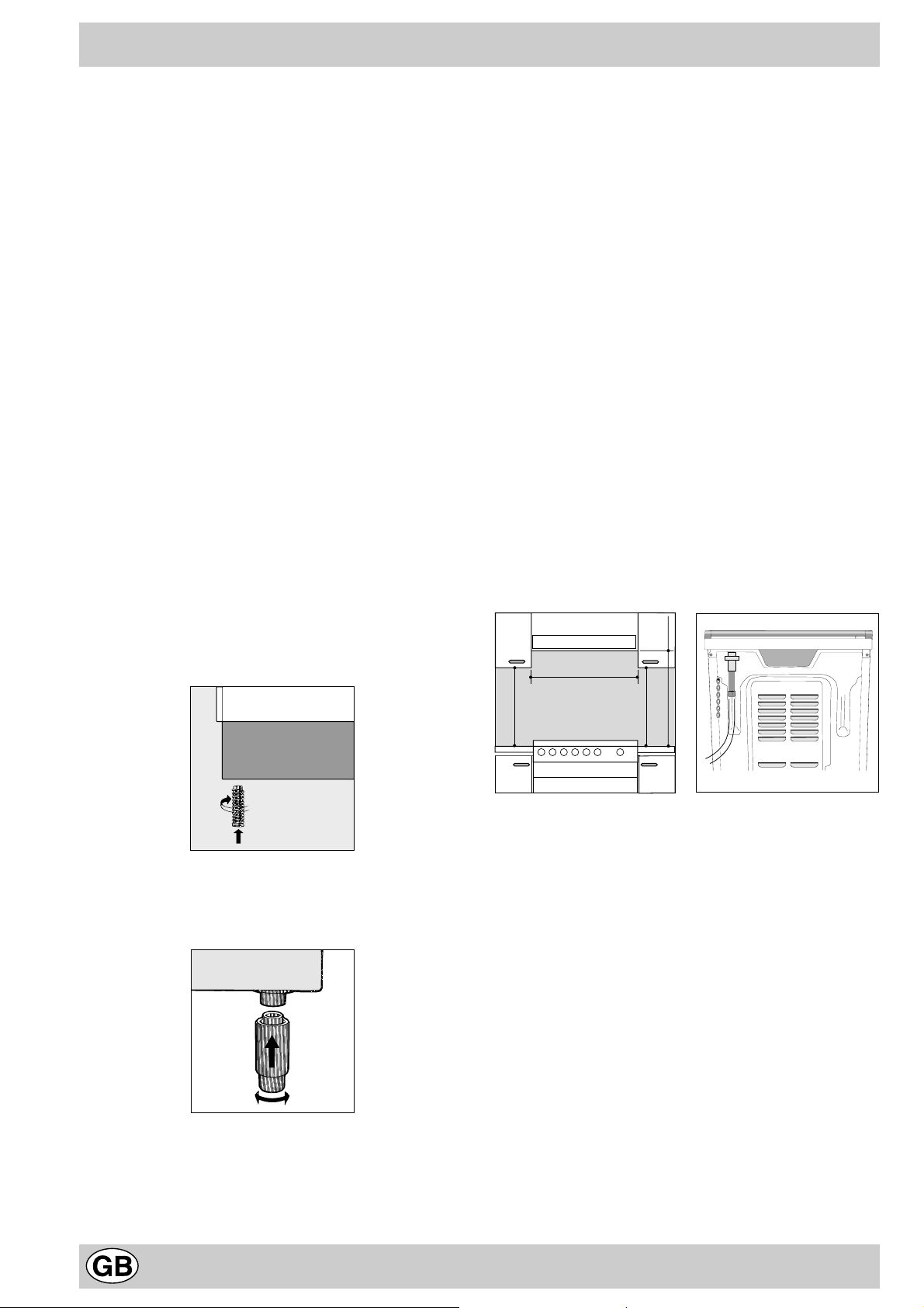
Installation
HOOD
420
Min.
min.
650
mm. with hood
min.
700
mm. without hood
mm.
600
Min. mm.
420
Min. mm.
All instruction on the following pages must be carried out
by a competent person (corgi registered) in compliance
with gas safety (installation and use) regulation 1984.
Important: disconnect the cooker from the electrycity
and gas supply when any adjustment, etc.
Positioning
Important: this unit may be installed and used only in
permanently ventilated rooms according to the British
Standards Codes Of Practice: B.S. 6172/B.S. 5440, Par. 2
and B.S. 6891 Current Editions. The following requirements
must be observed:
a) The cooker should not be installed in a bed sitting room
with a volume of less than 20m3. If it is installed in a room
of volume less than 5m3 an air vent of effective area of
110cm2 is required, if it is installed in a room of volume
between 5m3 and 10m3 a supplementary airvent area of
50cm2 is required, if the volume exceeds 11m3 no airvent
is required. Howev er , if the room has a door or a window
which opens directly to the outside no air vent is required
even when the v olume is between 5m3 and 11m3.
b) During prolonged use of the appliance you may consider
it necessary to open a window to the outside to improve
ventilation.
c) If there are other fuel burning appliances in the same
room, B.S.5440 Part 2 Current Edition, should, be
consulted to determine the requisite air vent requirements.
Levelling your appliance (only on a f e w models)
Your cooker is supplied with feet for le velling the appliance.
If necessary , these feet can be screwed into the housings
in the corners of the cooker base.
back panel of the cooker could reach a temperature of
50°C above room temperature. For proper installation of
the cooker, the following precautions must be taken:
a) The appliance can be placed in a kitchen, dining room
or bedsit, but not in a bathroom.
b) All furniture around the appliance must be placed at
least 200 mm from the top of the cooker, should the
surface of the appliance be higher than the worktop of
this furniture. Curtains should not be placed behind
the cooker or less than 200 mm away from the sides
of the appliance.
c) Any hoods must be installed according to the require-
ments in the installation manual for the hoods themselves.
d) If the cooker is installed beneath a wall cabinet, the
latter must be situated at a minimum of 420 mm above
the hob. The minimum distance between the worktop
and kitchen units made of combustible material is 700
mm (Fig. A).
e) The wall in direct contact with the back panel of the
cooker must be made of non-flammable materials.
f) The cooker is fitted with a safety chain that must be
attached to a hook, secured to the wall behind the
appliance.
Note: some models can have their gas connection
inverted. It is important to make sure the safety chain
is always situated on the side which corresponds to
the hose holder (Fig. B).
Mounting the legs (only on a few models)
Press-fit legs are supplied which fit under the base of your
cooker .
Installation of the cooker
The appliance can be installed next to furniture units which
are no taller than the top of the cooker hob. The wall in
direct contact with the back panel of the cooker must be
made of non-flammable material. During operation the
Fig. A Fig. B
Gas connection
The cooker should be connected to the gas-supply by a
corgi registered installer. During installation of this product
it is essential to fit an approved gas tap to isolate the supply
from the appliance for the conv enience of any subsequent
removal or servicing. Connection of the appliance to the
gas mains or liquid gas must be carried out according to
the prescribed regulation in force, and only after it is
ascertained that it is adaptable to the type of gas to be
used. If not, follow the instructions indicated in the
paragraph headed “Adaptation to diff erent gas types”. On
some models the gas supply can be connected on the left
or on the right, as necessary; to change the connection,
reverse the position of the hose holder with that of the cap
and replace the gasket (supplied with the appliance). In
the case of connection to liquid gas, by tank, use pressure
regulators that conform to the regulation in force. The gas
supply must be connected to the left of the appliance. Be
sure that the hose does not pass through the rear of the
cooker touching hot parts.
4
Page 5
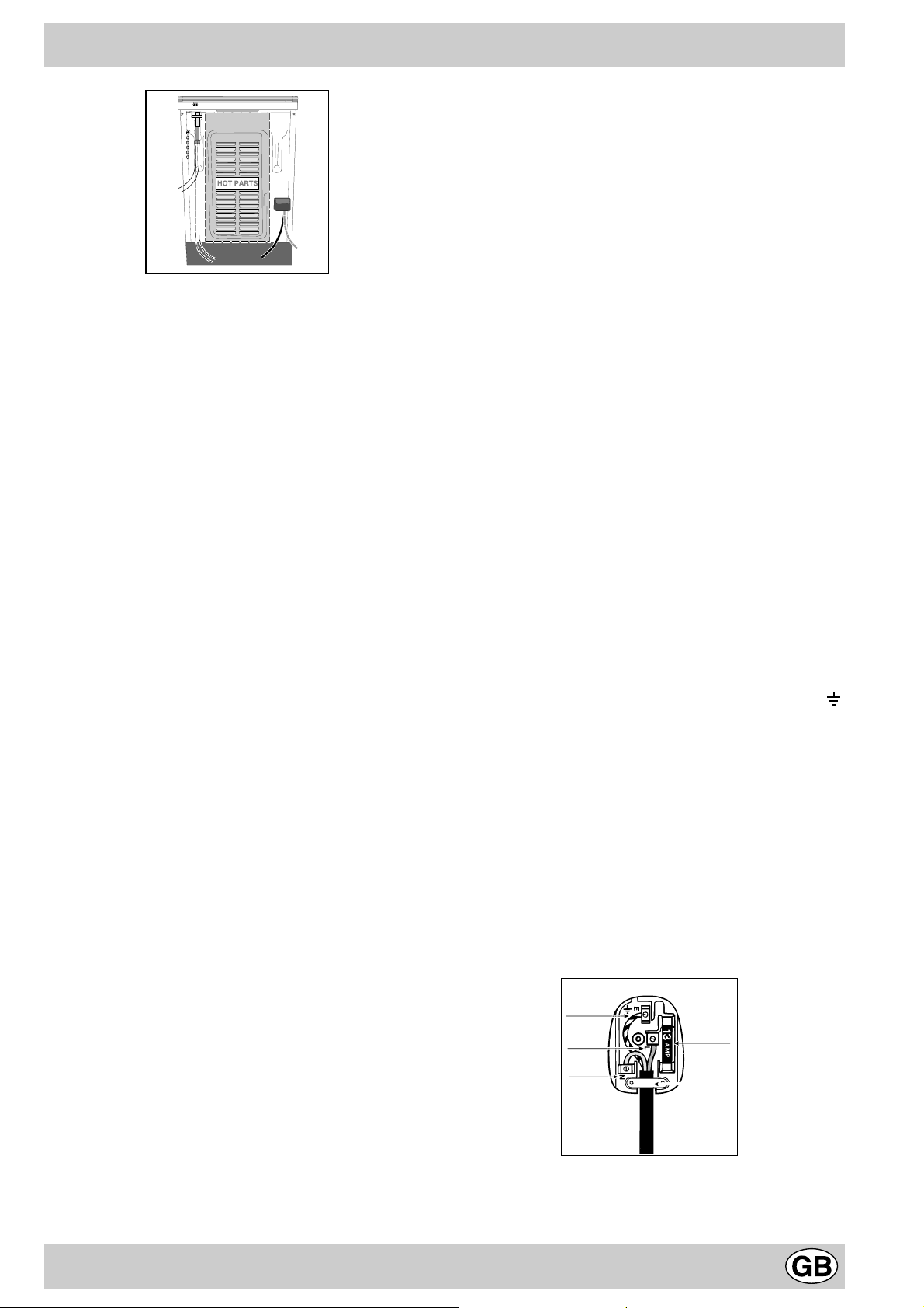
HOT PARTS
GREEN &
YELLOW
BROWN
BLUE
13 amp fuse
CROSS-BAR
CORD GRIP
Important: make sure the supply pressure conforms with
the values shown in the table entitled “Caracteristics of the
burners and nozzles”. When the cooker is installed
between cabinets (recessed), the gas connection must
be effected by an approved flexible hose with bayonet
fitting (BS 669 Current Edition). The gas inlet for the
cookers is a threaded G 1/2 gas female fitting.
Connecting the gas supply
To make the connection, a flexible hose should be used
corresponding to the current gas regulations which are:
• the hose must never be at any point in its lenght in contact
with the “hot” parts of the cooker;
• the hose must never be longer than 1,5 metre;
• the hose must not be subject to any tension or torsional
stress and it must not have an y excessively narrow curves
or bottlenecks;
• the hose must be easy to inspect along its entire length
to check its condition;
• the hose must always be in good condition, never attempt
to repair.
Important: the installation must comply with gas safety
(installation and use) regulations 1984. In all cases for the
above, b y low , a qualified, corgi approv ed engineer must be
called for installation.
Electrial connection
Pow er supply voltage and frequency: 230-240V a.c. 50/60 Hz.
Note: the supply cable must be positioned so that it never
reaches at any point a temperature 50°C higher than the
room temperature. The cable must be routed a way from the
rear vents. Should you require it, you ma y use a longer cable,
however, you must ensure that the cable supplied with the
appliance is replaced by one of the same specifications in
accordance with current standards and legislation.
Y our appliance is supplied with a 13 amp fused plug that can
be plugged into a 13 amp socket f or immediate use. Bef ore
using the appliance please read the instructions below.
WARNING - THIS APPLIANCE MUST BE EARTHED.
THE FOLLOWING OPERA TIONS SHOULD BE CARRIED
OUT BY A QU ALIFIED ELECTRICIAN.
Service Depot.
Removing the plug:
If your appliance has a non-rewireable moulded plug and
you should wish to remov e it to add a cable extension or to
re-route the mains cable through partitions, units etc., please
ensure that either:
• the plug is replaced by a fused 13 amp re-wireable plug
bearing the BSI mark of approval.
or:
• the mains cable is wired directly into a 13 amp cable outlet,
controlled by a switch, (in compliance with BS 5733) which
is accessible without moving the appliance.
Please note: for appliances with a rating greater than 13
amp (eg: electric hob , double ovens and freestanding electric
cookers etc.) the mains cable must be wired into a cooker
output point with a rating of 45 amp. In this case the cable is
not supplied.
Disposing of the plug:
Ensure that before disposing of the plug itself, y ou make the
pins unusable so that it cannot be accidentally inserted into
a socket. Instructions for connecting cable to an alternative
plug:
Important: the wires in the mains lead are coloured in
accordance with the following code:
Green & Yellow - Earth
Blue - Neutral
Brown - Live
If the colours of the wires in the mains lead do not correspond
with the coloured markings identifying the terminals in your
plug, proceed as follows:
Connect Green & Yellow wire to terminal marked “E” or
or coloured Green or Green & Yellow .
Connect Brown wire to terminal marked “L” or coloured Red.
Connect Blue wire to terminal marked “N” or coloured Black.
If a 13 amp plug (BS 1363) is used it must be fitted with a 13
amp fuse. A 15 amp plug must be protected by a 15 amp
fuse, either in the plug or adaptor or at the distribution board.
If you are in any doubt about the electrical supply to your
machine, consult a qualified electrician before use.
How to connect an alternative plug:
The wires in this mains lead are coloured in accordance with
the following code:
BLUE “NEUTRAL” (“N”)
BROWN “LIVE” (“L”)
GREEN AND YELLOW “EARTH” (“E”)
Replacing the fuse:
When replacing a faulty fuse, a 13 amp ASTA approved fuse
to BS 1362 should always be used, and the fuse cover refitted. If the fuse cover is lost, the plug must not be used until
a replacement is obtained.
Replacement fuse covers:
If a replacement fuse cover is fitted, it must be of the correct
colour as indicated by the coloured marking or the colour
that is embossed in words on the base of the plug.
Replacements can be obtained directly from your nearest
Disposing of the appliance
When disposing of the appliance please remove the plug by
cutting the mains cable as close as possible to the plug body
and dispose of it as described above.
5
Page 6
Adapting the cooker to different types of gas
In order to adapt the cooker to a different type of gas with
respect to the gas for which it was produced (indicated on
the label attached to the lid), follow these steps:
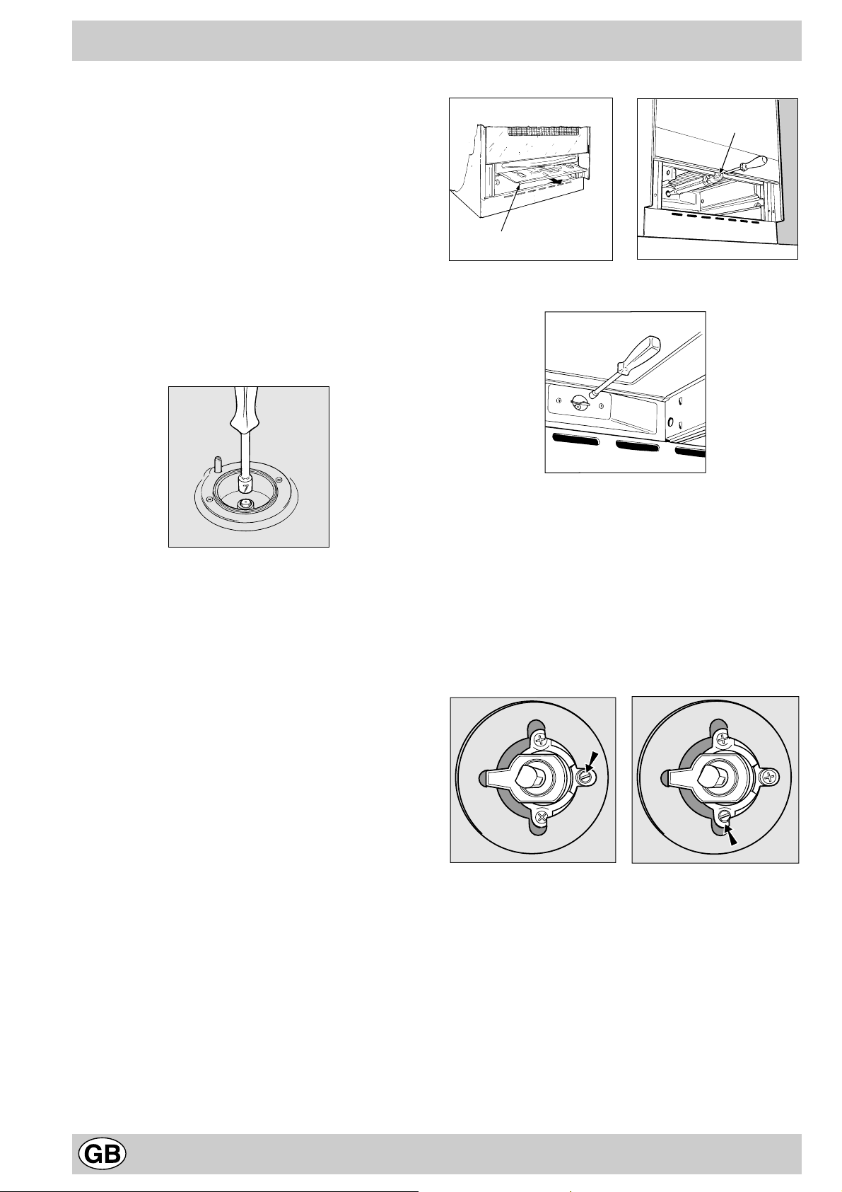
a) replace the hose holder mounted on the appliance with
that supplied in the bag of “cooker accessories”.
Important: the hose holder f or liquid gas is marked 8, the
hose holder for methane gas is marked 13. Alwa ys fit the
sealing gasket.
b) Replacing the burner nozzles on the hob:
• remove the grids and slide the burners from their
housings;
• unscrew the nozzles using a 7 mm socket spanner,
and replace them with nozzles for the new type of gas
(see table 1 “Burner and nozzle characteristics”).
• replace all the components by repeating the steps in
reverse order.
c) Minimum regulation of the hob burners:
•
turn the tap to minimum;
• remove the knob and adjust the regulation screw, which
is positioned in or next to the tap pin, until the flame is
small but steady.
N.B.: in the case of liquid gas, the regulation screw
must be screwed in to the bottom.
• check that the flame does not turn off when you turn
the tap quickly from high to low.
d Regulating the primary air of the burners:
The primary air of the burners requires no regulation.
V
A
Fig. C Fig. D
Fig.E
b) Minimum regulation of the gas oven burner with
thermostat (see fig.):
• light the burner as described in the paragraph “the o ven
knob” of the instruction booklet.
• tur n the knob to Max for about 10 minutes and then
turn the knob to the Min setting;
• remove the knob;
• regulate the screw positioned outside the thermostat
pin until the flame is small but steady.
N.B.: in the case of liquid gas, the regulation screw
must be screwed in to the bottom.
Adapting the gas oven to different types of gas
a) Replacing the oven burner nozzle:
• remove the warming drawer;
• remove the sliding protection “A” (see Fig.C);
• remove the screw and then the oven burner “V”(see
Fig. D). Remove the oven door to facilitate this
operation.
• unscrew the oven burner nozzle using the special
socket spanner for the nozzles (see Fig. E), or better
still a 7 mm socket spanner , and replace it with a nozzle
suited to the new type of gas (see table 1).
• check that the burner does not turn off when you turn
the knob from Max to Min and and when you open
and close the oven door quickly.
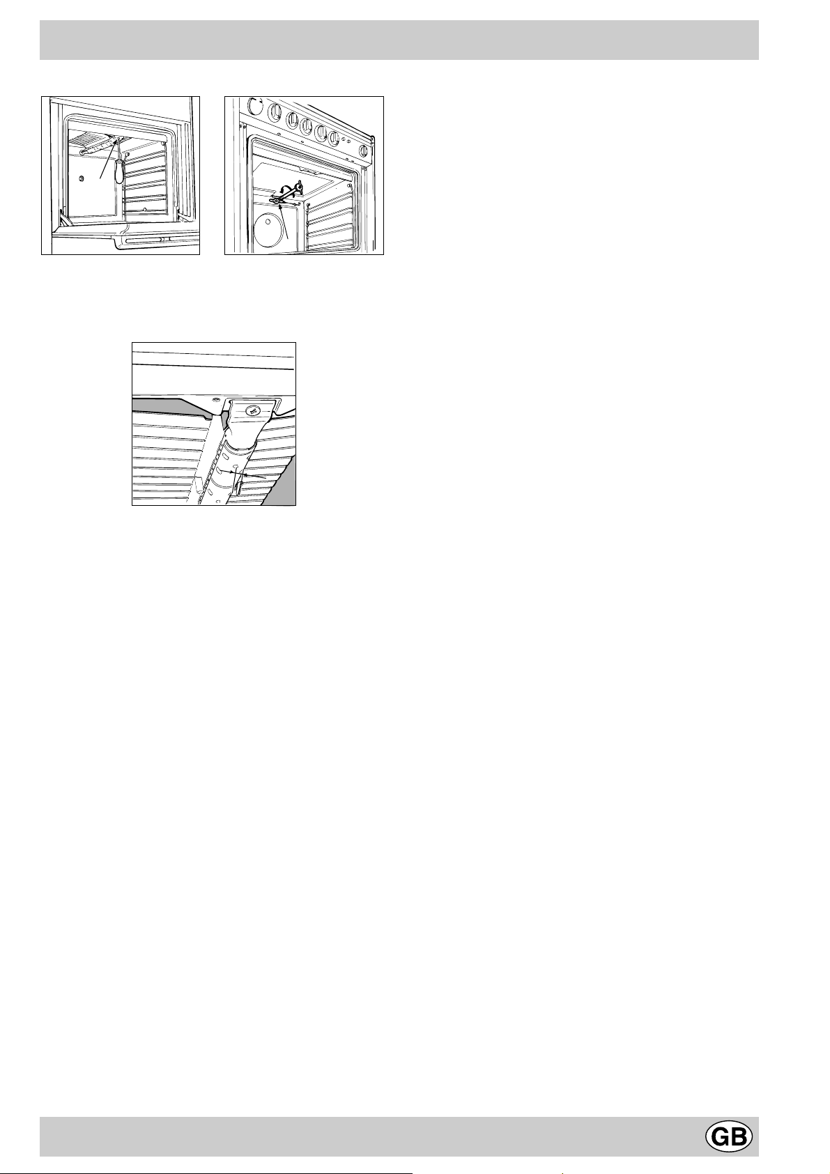
Adapting the gas grill to different types of gas
Replacing the nozzle of the grill burner:
• remove the screw and then slide out the grill burner “V”
(see Fig. F);
• unscrew the grill burner nozzle using the special socket
spanner for the nozzles (see Fig. G) or better still a 7 mm
socket spanner; replace the nozzle with a nozzle f or the new
type of gas (see table 1).
6
Page 7
V
I
Fig. F Fig. G
Important: when mounting the grill burner check that there is a
space of at least 4 mm between the security thermocouple (if
installed) and the burner.
4
m
m
Pay particular attention to the plug wires and
thermocouple tubes.
Important
On completion of the operation, replace the old rating
sticker with one indicating the new type of gas used. This
sticker is available from our Service Centres.
Note
Should the pressure of the gas used be different (or vary)
from the recommended pressure, it is necessary to fit a
suitable pressure regulator onto the inlet pipe in
compliance with current National Regulations relative to
“regulators for channelled gas”.
7
Page 8
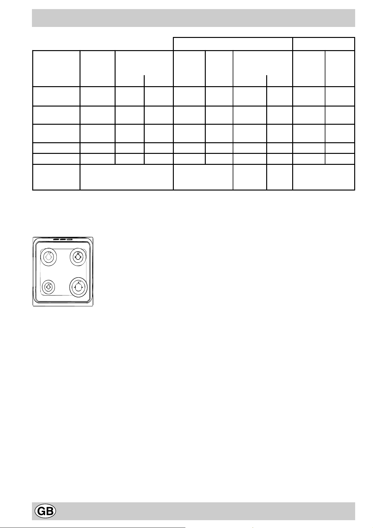
Burner and nozzle characteristics
Table 1 Liquid Gas Natural Gas
Burner Diameter
(mm)
Thermal Power
kW (p.c.s.*)
By-Pass
1/100
Nozzle
1/100
Flow*
g/h
Nozzle
1/100
Flow*
Nominal Reduced (mm) (mm) *** ** (mm)
Fast
(Large)(R)
Semi Fast
(Medium)(S)
Auxiliary
(Small)(A)
100 3.00 0.7 41 86 218 214 116 286
75 1.90 0.4 30 70 138 136 106 181
55 1.00 0.4 30 50 73 71 79 95
Oven - 3.10 1.0 46 85 225 221 132 295
Grill - 2.50 - - 80 182 179 122 227
Supply
Pressures
Nominal (mbar)
Minimum (mbar)
Maximum (m bar)
28-30
20
35
37
25
45
20
17
25
* At 15°C and 1013 mbar- dry gas
** Propane P.C.S. = 50,37 MJ/Kg
*** Butane P.C.S. = 49,47 MJ/Kg
Natural P.C.S. = 37,78 MJ/m
3
l/h
A
K 34 G/G
K 340 G/G
K 341 G/G
K 342 G/G
K 344 G/G
S
S
R
8
Page 9
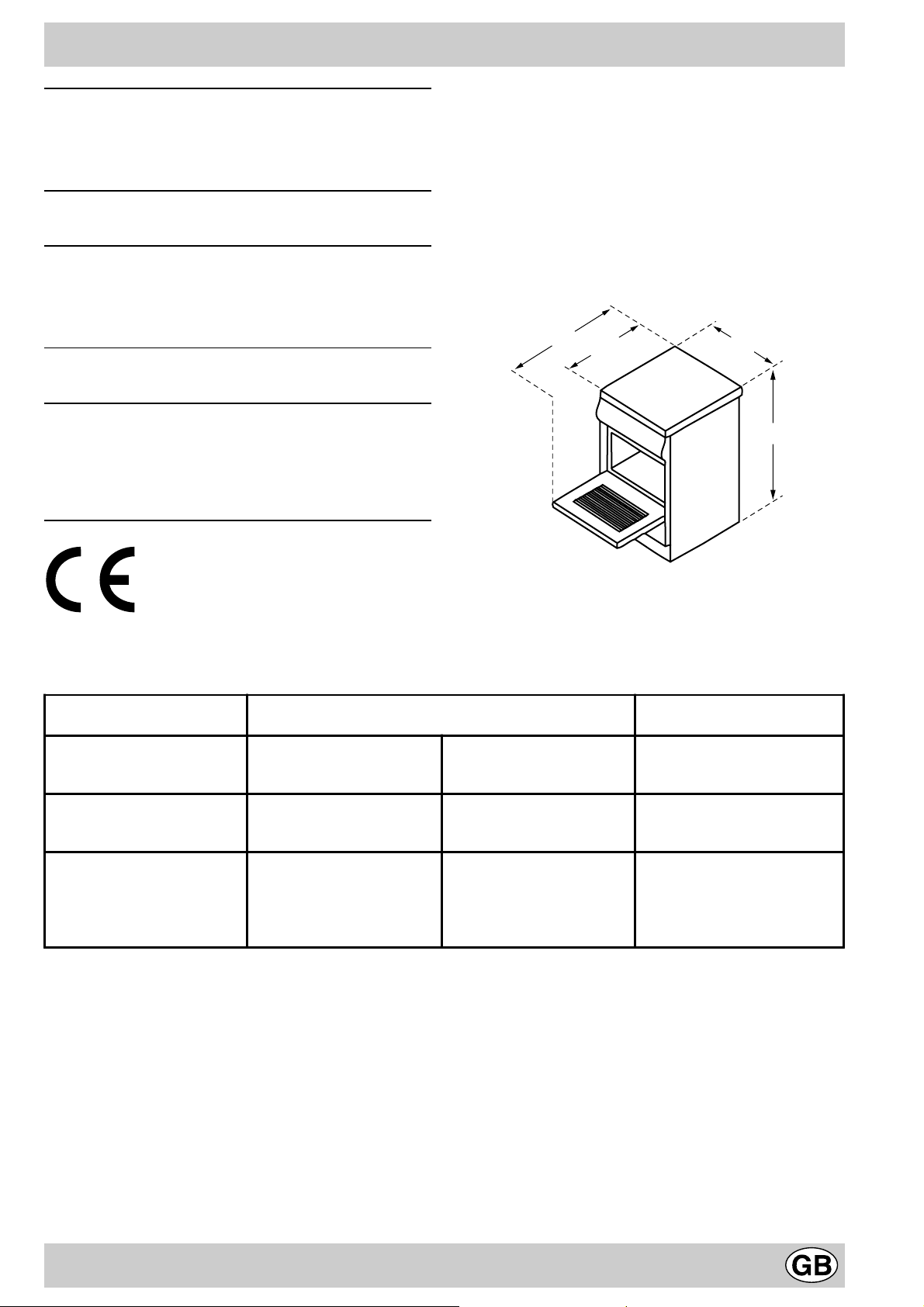
Technical characteristics
104
60
50
85/90
Inner dimensions of the oven:
Width: 39 cm
Depth: 44 cm
Height: 34 cm
Inner Volume of the Oven:
58 lt
Inner Dimensions of the Food Warmer:
Width: 42 cm
Depth: 44 cm
Height: 17 cm
Voltage and Frequency of Power Suppl y:
see data plate
Burners:
adaptable for use with all the types of gas indicated on
the data plate situated inside the flap or, once the
dishwarmer drawer has been opened, on the inside wall
of the left-hand side panel.
This appliance conforms with the following Eur opean
Economic Community directives:
- 73/23/EEC of 19/02/73 (Low V oltage) and subsequent
modifications;
- 89/336/EEC of 03/05/89 (Electromagnetic
Compatibility) and subsequent modifications;
- 90/396/EEC of 29/06/90 (Gas) and subsequent
modifications;
- 93/68/EEC of 22/07/93 and subsequent modifications.
Mains frequency and voltage of the electric section and charac teristics of the gas secti on
Model Gas section Electric section
Class
K 34 G/G II2H3+
K 340 G/G
K 341 G/G
K 342 G/G
K 344 G/G
(1) The values in g/h ref er to the c apaci ties with l iquid ga s (Butan e, Propan e).
II2H3+
Rated power
kW (1)
10.9 (793 g/h - G30)
(778 g/h - G31)
10.9 (793 g/h - G30)
(778 g/h - G31)
230-240V~ 50/60Hz
Voltage
9
Page 10
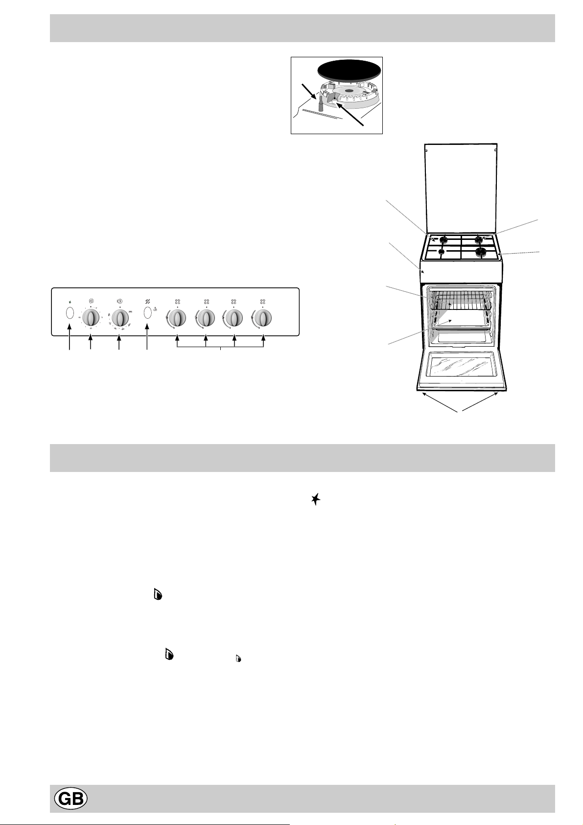
The cooker with gas oven
F
A
E
K
G
D
B
A Tray f or Catching Overflows
B Gas Burner
C Flame Failure Device for Cooktop Burners (only a
few models)
D Top Grate
E Control Panel
F Adjustable Feet or Legs
G Dripping Pan or Baking Sheet
H Electronic Lighting Device (only a fe w models)
K Oven Rack
L Electronic Lighting for Hob Burners (only on certain
models)
M Oven and Grill Control Knob
N Control Knobs for Gas Burners on Hob
O Button for Oven Light (only a few models)
P Timer Knob (only a few models)
C
H
P
L
The various functions included in the cooker are selected by
operating the control devices located on the cooker control panel.
Control Knobs for the Gas Burners on the Hob (N)
The position of the gas burner controlled by each one of the
knobs is shown by a symbol of a solid ring:•. T o light one of the
burners, hold a lighted match or lighter near the burner. Press
down and turn the corresponding knob in the counter-clockwise
direction to the maximum setting. Each burner can be operated at its maximum, minimum or intermediate power . Shown
on the knob are the different symbols for off • (the knob is on this
setting when the symbol lines up with the reference mark on the
control panel), for maximum and minimum .
To obtain these settings, turn the knob counter-clockwise with
respect to the off position. To turn off the burner, turn the knob
clockwise until it stops (corresponding again with the • symbol).
Electronic Ignition for the Gas Hob
Some of the models are provided with instant electronic lighting
of the hob gas burners; these models are identified by the presence of a lighting device (see detail H). This device operates
when a slight pressure is applied to the “L” button marked with
O
MN
The different functions and uses of the oven
symbol. To light a specific burner just press the button la-
belled “L” while pushing the corresponding knob all the wa y in
and turning it counter-clockwise until it lights. For immediate
lighting, first press the b utton and then turn the knob.
Important: Should the burner flames accidentally go out,
turn off the control knob and wait at least 1 minute before
trying to relight.
Models with Hob Gas Burner Safety Devices to Prevent
Leaks (only on certain models)
These models can be identified by the presence of the device
itself (see detail C).
Important: Since the hob burners are equipped with a safety
device, you m ust hold the control knob in for about 6 seconds
after the burner has been lighted to allow the gas to pass until
the safety thermocouple has heated.
Gas Cut Off (only on certain models)
This cooker has a safety cut out feature which switches
off the burners when you close the cover. This device is
provided as a safety feature in case the co ver is lowered
with the burners on.
Attention: after the re-opening of the glass co ver in order
to restore the gas cut-off, it is necessary to press manually
the push-button situated in the posterior part to r ight of
10
Page 11
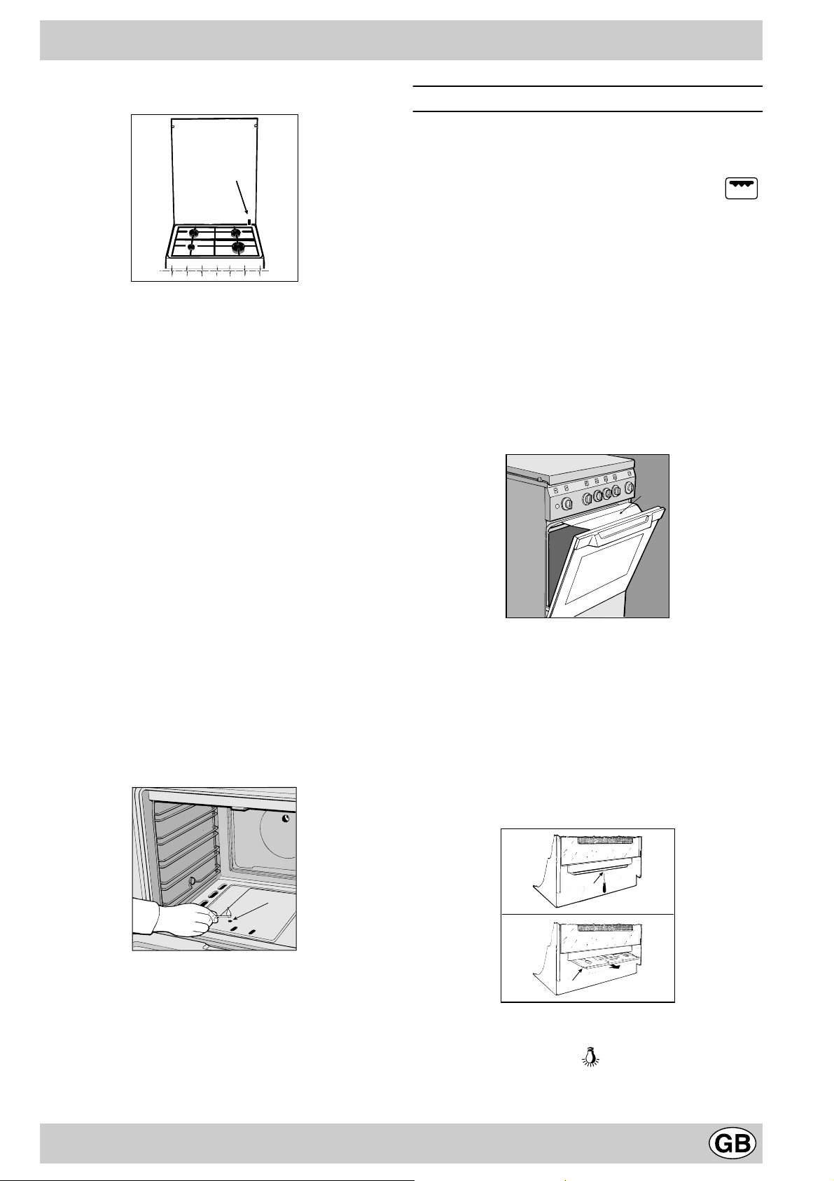
the hob of the cooker (as indicated in figure).
D
Always turn off the gas and allow the burners to cool before
closing the cover . F ailure to f ollow these instructions may
cause the glass cover to shatter. Keep the cover open
when using the oven.
Attention: before using the o ven and grill for the first time , turn
the oven on f or approximately one half hour. Make sure that the
oven is empty, the thermostat on high, the door open, and the
room properly ventilated. The odor which can be detected at
times is due to the ev aporation off the substances used to protect
the oven and the grill during the period between the time of
production and installation of the appliance.
Min • 150 • 180 • 220 Max
140 145 160 200 250
The temperature setting is then automatically reached and kept
constant by the thermostat (which is controlled by the knob).
To use the grill, turn the knob clockwise till to setting ,
after holding a lighted match or a lighter close to the grill burner.
In the grill burner equipped with a safety device, the knob
must be held pressed in for about 6 seconds in order to
activate the flame failure device. In this wa y the infr ared r a y
comes on for browning the food or cooking roast, chops,
sausages, roast-beef, etc.; for grill cooking, place a drip-pan under
the grill to catch the grease.
Important Notice: In the event the flame f or the oven accidentally goes out, turn the control knob for the burner to the off
position and do not relight the burner for at least one minute.
Important: when using the gr ill, the oven door must be
left partly open by positioning the deflector “D” between
door and panel to prevent the cooker knobs from
overheating.
Attention: Only use the bottom shelf of the oven when using
the rotisserie to cook (where present). For all other types of
cooking, never use the bottom shelf and ne ver place anything
on the bottom of the oven when it is in operation because this
could damage the enamel. Always place your cookware (dishes,
aluminium foil, etc. etc.) on the grate provided with the appliance
inserted especially along the oven guides.
Oven and Grill Control Knob (M)
This knob allows you to select the various f eatures of the ov en
and to set the most appropriate cooking temperature from among
those indicated on the knob itself (between Min and Max).
T o light the o ven burner, hold a lighted match or lighter near the
"F" hole and, at the same time, press down and turn the oven
knob counter-clockwise to the Max setting.
F
Attention
Avoid the children touch the oven door because it is very hot
during the cooking.
WARNING
To remove the sliding protection “A”, unscrew screw “S”.
When you hav e finished, replace the protection and lock
it in place with screw “S”.
Before using the oven, make sure the sliding protection
“A” is fastened in the correct position.
S
Since the cooker is equipped with a safety device which
makes it necessary to keep the knob pressed in for about 6
seconds after the burner has been lighted to allow the gas
to pass through freely .
The cooking temperature is selected by matching the desired
temperature with the reference mark on the panel; the complete
range of temperatures is shown below .
A
Oven Light Button (O)
This button is marked by the symbol and s witches on the
light inside the oven so that you can monitor the cooking proc-
ess without opening the door.
11
Page 12
Cooking Control Timer Knob (only a few models)
Some models are equipped with a timer program to control when
the oven shuts off during cooking. T o use this f eature, y ou must
wind the "P" knob one full turn in the counter-clockwise direction
; Then, turn the knob in the clockwise direction , to set the
time by matching up the indicator on the control panel with the
number of minutes on the knob.
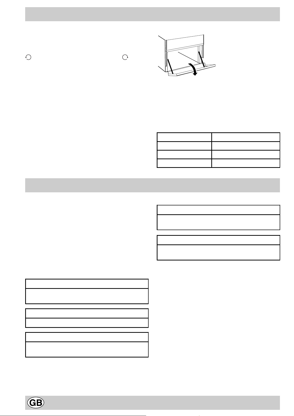
Storage recess below the oven (only a f e w models)
Below the oven a recess can be used to contain cooking pans
and cooker accessories. Moreover, during ov en operation, it may
be used to keep food warm.To open the storage is necessary
turn it downwards.
Caution: this storage recess must not be used to store
inflammable materials.
Practical advice for burner use
In order to get the maximum yield it is important to remember
the following:
· Use appropriate cookware f or each burner (see table) so as
to avoid flames ov ershooting the edges.
· At boiling point turn the knob to minimum.
· Use cookw are with lids.
· Alwa ys use cookware with flat bottoms.
Burner ø Cookware diameter (cm)
Fast (R) 24 - 26
Semi Fast (S) 16 - 20
Auxiliary (A) 10 - 14
Cooking advice
The oven off ers a wide range of alternatives which allow
you to cook any type of food in the best possib le wa y . With
time you will learn to make the best use of this versatile
cooking appliance and the following directions are only a
guideline which may be varied according to your o wn personal experience.
Baking cakes
The oven should alwa ys be warm before putting in cak es
wait till the end of preheating (about 10-15 min.). Cakebaking temperatures are normally around 160°C/200°C.
Do not open the oven door during the baking process as
this could cause the cake to sink.In general:
Pastry is too dry
Increase the temperature by 10°C and reduce the
cooking time.
Pastry dropped
Use less liquid or lower the temperature by 10°C.
Pastry is too da rk on t op
Cooked well on the inside but sticky on the outside
Use less liquid, l ower the temperature, and increas e the
cooking time.
The pastry sticks to the pan
Grease the pan well and sprinkl e it wit h a dusting of
flour or use greaseproof paper.
Cooking fish and meat
When cooking white meat, fowl and fish use low
temperatures. (150°C-175°C). When red meat must be
superficially well-cooked but succulent inside, it is
advisable to start with a high temperature (200-220°C)
for a short time, and then to reduce it at a later point.
Generally speaking, the more meat there is, the lower the
temperature and the longer the cooking time should
be.Place the meat in the centre of the grid and put a spilltray underneath to catch grease drips. Insert the grid so
that it is in the middle of the oven. If more heat from below
is required, use the 1° bottom shelf.
Place it on a lower rack, lower the temperature, and
increase the cooking t ime.
12
Page 13
Cooker routine maintenance and cleaning
Before each operation, disconnect the cooker from
the electricity .To assure the long life of the cooker, it must
be thoroughly cleaned frequently, keeping in mind that:
· the enamelled parts and the self-cleaning panels are
washed with warm water without using any abrasive
powders or corrosive substances which could ruin
them;
· the inside of the oven should be cleaned fairly often
while it is still warm using warm water and detergent,
followed by careful rinsing and drying;
· the flame spreaders should be washed frequently with
hot water and detergent taking care to eliminate any
scale;
· in cookers equipped with automatic lighting, the
terminal part of the electronic instant lighting devices
should be cleaned frequently and the gas outlet holes
of the flame spreaders should be checked to make
sure they are free of any obstructions;
· Stainless steel may become marked if it comes into
contact with very hard water or harsh detergents
(containing phosphorous) for long periods of time. After
cleaning, it is advisable to rinse thoroughly and dry. It
is also recommended to dry any water drops;
• On models with glass covers, the covers should be
cleaned with hot water; the use of rough cloths or
abrasives is to be av oided.
N.B: avoid closing the cover while the gas burners
are still warm. Remove any liquid from the lid before
opening it.
Important: per iodically check the wear of the gas hose
and substitute it if there are any defects; we recommended
changing it every year .
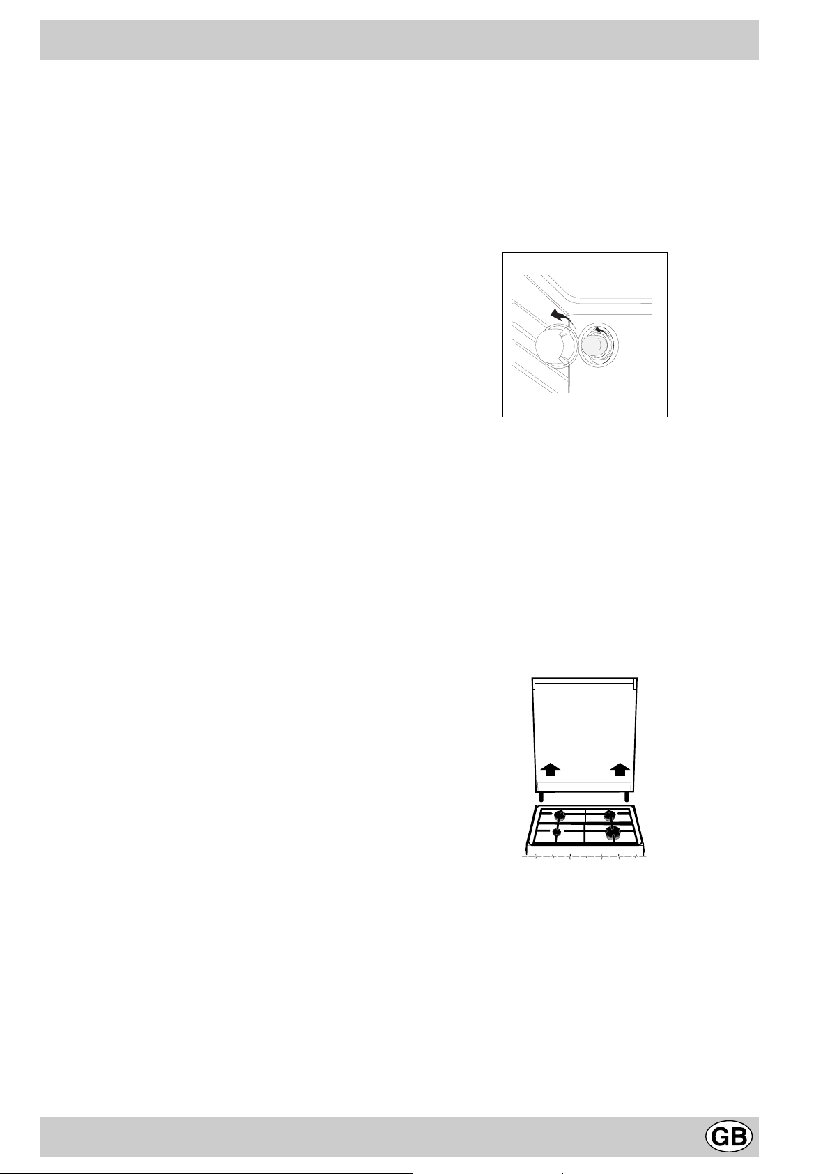
Replacing the oven lamp
· Unplug the oven from the mains;
· Remove the glass cover of the lamp-holder;
· Remove the lamp and replace with a lamp resistant to
high temperatures (300°C) with the following
characteristics::
- V oltage 230V
- Wattage 25W
- T ype E14
· Replace the glass cover and reconnect the oven to
the mains.
Greasing the taps
The taps may jam in time or they ma y become difficult to
turn. If so , they must be cleaned internally and the grease
replaced.
N.B: This operation must be carried by a technician
authorised by the manufacturer .
Removing the lid
The cooker lid can be remov ed to f acilitate cleaning. To
remove the lid, first open it completely and pull it
upwards (see figure)
13
Page 14
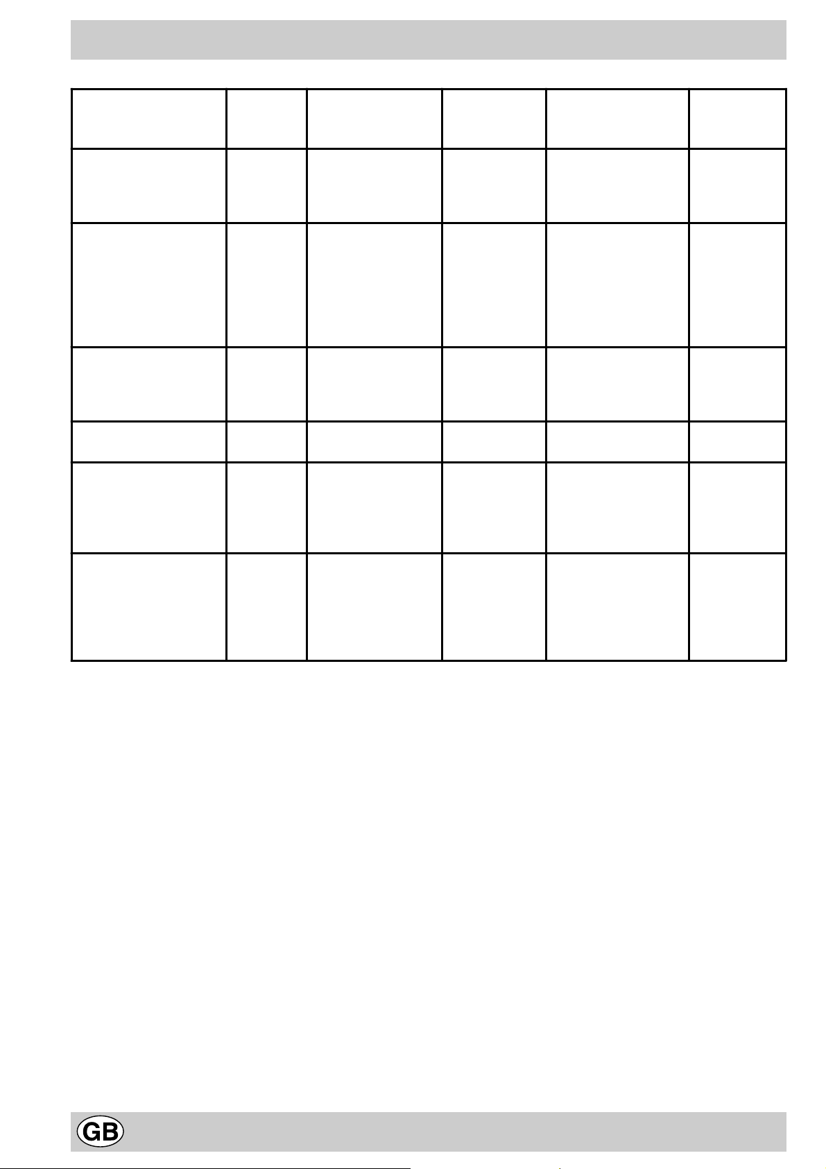
Pratical advice for oven cooking
Food to be cooked
Pasta
Lasagne
Cannelloni
Pasta bakes au gratin
Meat
Veal
Chicken
Duck
Rabbit
Pork
Lamb
Fish
Mackerel
Dentex
Trout baked in paper
Pizza
Napolitan
Cake
Biscuits
Tarts
Savoury pie
Raised Ca kes
Wt.
(Kg)
2.5
2.5
2.5
1.7
1.5
1.8
2.0
2.1
1.8
1.1
1.5
1.0
1.0 3 220 15 15-20
0.5
1.1
1.0
1.0
Cooking posit ion of
shelves from
bottom
3
3
3
3
3
3
3
3
3
3
3
3
3
3
3
3
Temperature
(°C)
210
200
200
200
220
200
200
200
200
180-200
180-200
180-200
180
180
180
165
Pre-heating time
(min)
10
10
10
10
10
10
10
10
10
10
10
10
15
15
15
15
Cooking time
(min.)
60-75
40-50
40-50
85-90
90-100
100-110
70-80
70-80
90-95
35-40
40-50
40-45
30-35
30-35
45-50
35-40
Grill cooking
Veal steaks
Cutlet s
Hamburger s
Mackerels
Toast sandwiches
NB: cooking times are approximate and may vary according to personal taste. When cooking using the grill, the
dripping-pan must always be placed on the 1st oven rack from the bottom.
1
1,5
1
1
n.° 4
4
4
3
4
4
5
5
5
5
5
15-20
20
7
15-20
5
14
Page 15

15
Page 16

Merloni Elettrodomestici
Viale Aristide Merloni 47
60044 Fabriano
Italy
Tel +39 0732 6611
Fax +39 0732 662501
www .merloni.com
Cucina con forno e grill gas (Spec. GB)
12/01 - 195030452.05 Xerox Business Services - Docutech
 Loading...