

INDESIT IWDE12 User Manual [fr]

Instructions for use
WASHER-DRYER
GB
English,1
IWDE 12
FR
Français,15
Contents
GB
Installation, 2-3-4-5
Unpacking and levelling
Electric and water connections
The first wash cycle
Technical details
Instructions for the fitter
Washer-dryer description, 6-7
Control panel
Leds
Starting and Programmes, 8
Briefly: how to start a programme
Programme table
Personalisations, 9
Setting the temperature
Setting the drying cycle
Functions
Detergents and laundry, 10
Detergent dispenser
Preparing your laundry
Special items
Precautions and advice, 11
General safety
Disposal
Saving energy and respecting the environment
Care and maintenance, 12
Cutting off the water or electricity supply
Cleaning your appliance
Cleaning the detergent dispenser
Caring for your appliance door and drum
Cleaning the pump
Checking the water inlet hose
Troubleshooting, 13
Service, 14
Before calling for Assistance
1
Installation
GB
Keep this instruction manual in a safe place for
future reference. Should the appliance be sold,
transferred or moved, make sure the instruction
manual accompanies the Washer-dryer to inform the
new owner as to its operation and features.
Read these instructions carefully: they contain vital
information on installation, use and safety.
Unpacking and levelling
Unpacking
1. Unpack the Washer-dryer.
2. Check whether the Washer-dryer has been
damaged during transport. If this is the case, do not
install it and contact your retailer.
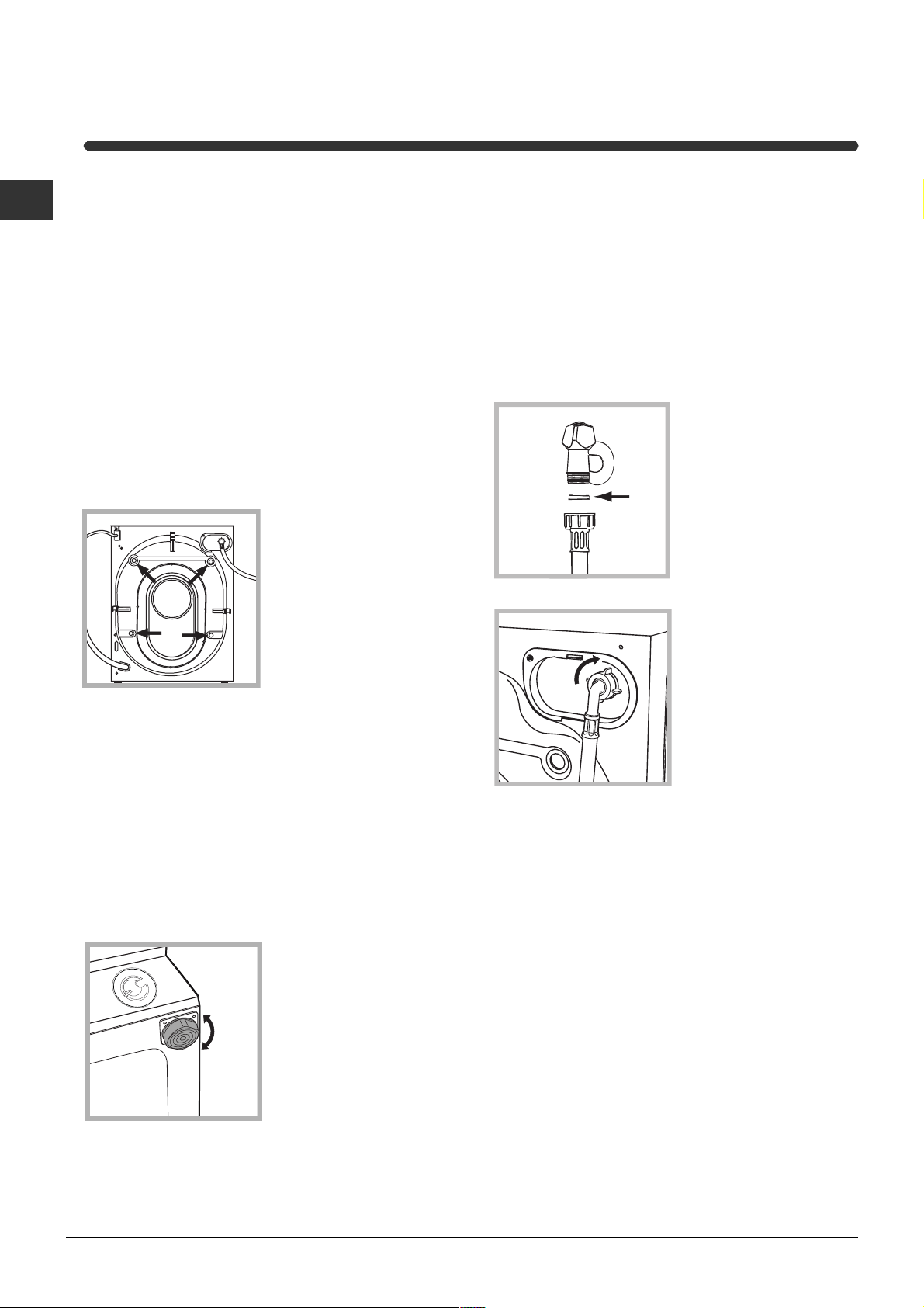
3. Remove the four
protective screws and
the rubber washer with
the respective spacer,
situated on the rear of
the appliance (see
figure).
4. Seal the gaps using the plastic plugs provided.
5. Keep all the parts: you will need them again if the
Washer-dryer needs to be moved to another
location.
Levelling your appliance correctly will provide it with
stability and avoid any vibrations, noise and shifting
during operation. If it is placed on a fitted or loose
carpet, adjust the feet in such a way as to allow
enough room for ventilation beneath the Washerdryer.
Electric and water connections
Connecting the water inlet hose
1. Insert seal A into the
end of the inlet hose
and screw the latter
onto a cold water tap
A
with a 3/4 gas threaded
mouth (see figure).
Before making the
connection, allow the
water to run freely until
it is perfectly clear.
2. Connect the other end
of the water inlet hose to
the Washer-dryer,
screwing it onto the
appliance's cold water
inlet, situated on the top
right-hand side on the
rear of the appliance
(see figure).
Packaging materials are not children's toys.
Levelling
1. Install the Washer-dryer on a flat sturdy floor,
without resting it up against walls, furniture cabinets
or other.
2. If the floor is not
perfectly level, compensate for any unevenness
by tightening or
loosening the adjustable
front feet (see figure);
the angle of inclination,
measured according to
the worktop, must not
exceed 2°.
2
3. Make sure there are no kinks or bends in the
hose.
The water pressure at the tap must be within the
values indicated in the Technical details table
(on the next page).
If the water inlet hose is not long enough, contact
a specialist store or an authorised serviceman.
Never use hoses that have already been used.
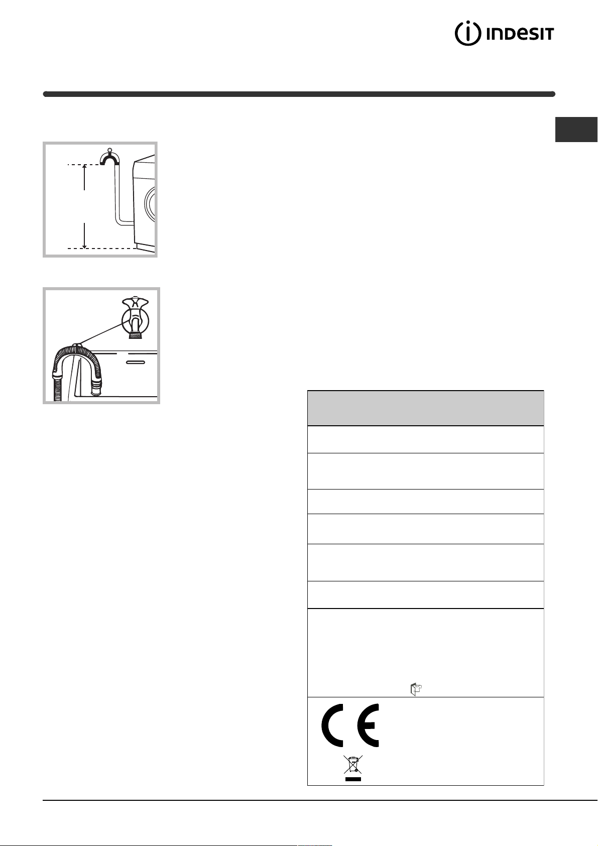
Connecting the drain hose
65 - 100 cm
Connect the drain hose,
without bending it, to a
draining duct or a wall
drain situated between
65 and 100 cm from
the floor;
Do not use extensions or multiple sockets.
GB
The power supply cable must never be bent or
dangerously compressed.
The power supply cable must only be replaced by
an authorised serviceman.
Warning! The company denies all liability if and when
these norms are not respected.
The first wash cycle
alternatively, place it
over the edge of a
basin, sink or tub,
fastening the duct
supplied to the tap (see
figure). The free end of
the hose should not be
underwater.
We advise against the use of hose extensions; in
case of absolute need, the extension must have the
same diameter as the original hose and must not
exceed 150 cm in length.
Electric connection
Before plugging the appliance into the mains
socket, make sure that:
the socket is earthed and in compliance with the
applicable law;
the socket is able to sustain the appliance's
maximum power load indicated in the Technical
details table (on the right);
Once the appliance has been installed, and before
you use it for the first time, run a wash cycle with
detergent and no laundry, setting the 90°C
programme without a pre-wash cycle.
Technical details
Model
Dimensions
Capacity
Electric
connections
Wat er
connections
Spin speed
IWDE 12
59.5 cm wide
81.5 cm high
54,5 cm deep
from 1 to 6 kg for the wash programme;
from 1 to 5 kg for the drying programme
please refer to the technical data plate
fixed to the machine
maximum pressure 1 MPa (10 bar)
minimum pressure 0.05 MPa (0.5 bar)
drum capacity 52 litres
up to 1200 rpm
the supply voltage is included within the values i
ndicated on the Technical details table
(on the right);
the socket is compatible with the washing
machine's plug. If this is not the case, replace
the socket or the plug.
The washing machine should not be installed in an
outdoor environment, not even when the area is
sheltered, because it may be very dangerous to
leave it exposed to rain and thunderstorms.
When the washing machine is installed, the mains
socket must be within easy reach.
Control
programmes
according to
EN 50229
directive
Wash:
programme 2; temperature 60°C;
run with a load of 6 kg.
Drying: first drying cycle performed with
a 1 kg load, by selecting a drying time of
60 min;
Second drying cycle performed with a 5
kg load and the DRYING knob on
the setting.
This appliance is compliant with the
following European Community
Directives:
- 89/336/CEE of 03/05/89
(Electromagnetic Compatibility) and
subsequent amendments
- 2002/96/CE
- 2006/95/CE (Low Voltage)
3
GB
Instructions for the fitter
Mounting the wooden panel onto the door and
inserting the machine into cabinets:
In the case where the machine must be shipped for final
installation after the wooden panel has been mounted, we
suggest leaving it in its original packaging. The packaging
was designed to make it possible to mount the wooden
panel onto the machine without removing it completely
(see figures below).
The wooden panel that covers the face of the machine
must not be less than 18 mm in thickness and can be
hinged on either the right or left. For the sake of
practicality when using the machine, we recommend that
the panel be hinged on the same side as the door for the
machine itself - the left.
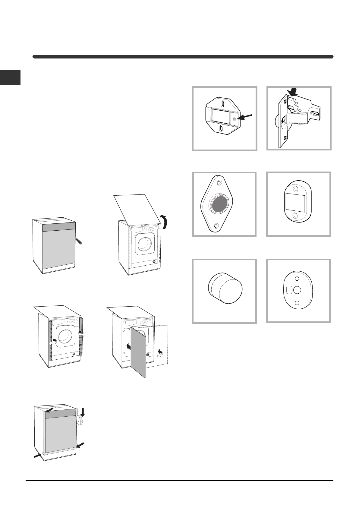
Door Mounting Accessories (Fig. 1-2-3-4-5).
N° 2 Hinge Supports
Fig. 1
N° 1 Magnet N° 1 Magnet plate
Fig. 3 Fig. 4
Fig. 2
N° 2 Hinges
A
C
Tur seite
E
B
D
N° 1 Rubber plug
Fig. 5
- No. 6 type A self-threading screws, l =13 mm.
- No. 2 type B metric, countersunk screws, l =25; for
fastening the magnet plate to the cabinet.
- No. 4 type C metric screws, l =15 mm; for mounting the
hinge supports to the cabinet.
- No. 4 type D metric screws, l =7 mm; for mounting the
hinges on the supports.
Mounting the Parts onto the Face of the Machine.
- Fit the hinge supports to the appliance front panel,
positioning the hole marked with an arrow in fig. 1 so that it
is on the inner side of the front panel. Fit a spacer (fig. 4/B)
between the surfaces using type C screws.
- Fit the magnet plate at the top of the opposite side,
using type B screws to fix two spacers (fig. 4/B) between
the plate and the surface.
Fig. 4/B
N° 4 Spacers
4
Using the Drilling Template.
- To trace the positions of the holes on the left-hand side
of the panel, align the drilling template to the top left side
of the panel using the lines traced on the extremities as a
reference.
- To trace the positions of the holes on the right-hand
side of the panel, align the drilling template to the top
right side of the panel.
- Use an appropriately sized router to mill the holes for
the two hinges, the rubber plug and the magnet.
Mounding the Parts onto the Wooden Panel (Door).
- Insert the hinges into the holes (the movable part of the
hinge must be positioned facing away from the panel) and
fasten them with the 4 type A screws.
- Insert the magnet into the top hole on the opposite side
of the hinges and fasten it with the two type B screws.
- Insert the rubber plug into the bottom hole.
The panel is now ready to be mounted onto the machine.
Mounting the Panel into the machine.
Insert the nib of the hinge (indicated by the arrow in fig. 2)
into the hole for the hinge and push the panel towards the
front of the machine. Fasten the two hinges with the type
D screws.
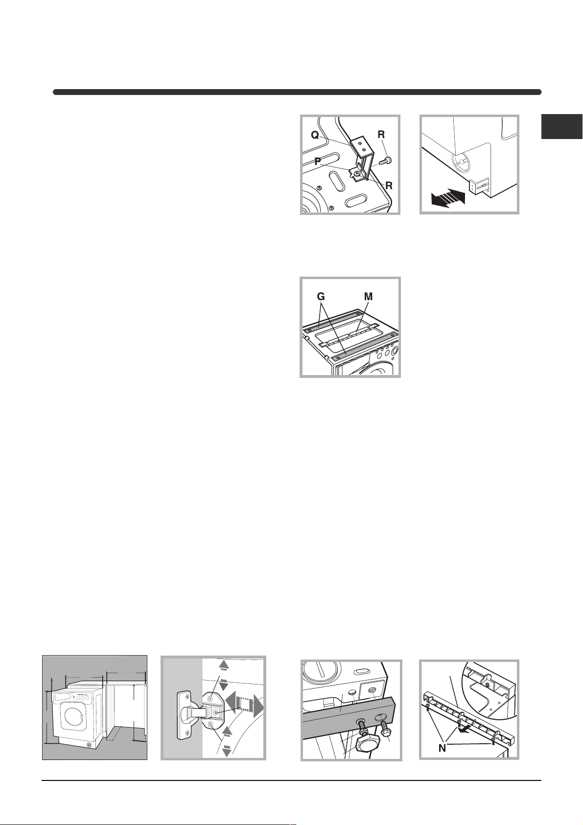
Fastening the plinth guide.
If the machine is installed at the end of a set of modular
cabinets, mount either one or both of the guides for the
base molding (as shown in fig. 8). Adjust them for depth
based on the position of the base molding, and, if
necessary, fasten the base to the guides (fig. 9).
This is how to assemble the plinth guide (fig. 8):
Fasten angle P using screw R, insert plinth guide Q into
the special slot and once it is in the desired position, lock
it in place using angle P and screw R.
Inserting the machine into the Cabinet.
- Push the machine into the opening, aligning it with the
cabinets (fig. 6).
- Regulate the adjustable feet to raise the machine to the
appropriate height.
- To adjust the position of the wooden panel in both the
vertical and horizontal directions, use the C and D
screws, as shown in fig. 7.
Important: close the lower part of the appliance front by
ensuring that the plinth rests against the floor.
GB
Fig. 8 Fig. 9
Accessories provided for the height adjustment.
The following can be found inside the polystyrene lid (fig. 10):
2 crossbars (G), 1 strip (M)
the following can be found inside
the appliance drum:
4 additional feet (H),
4 screws (I),
4 screws (R),
4 nuts (L),
2 plinth guides (Q)
Fig. 10
Adjusting the appliance height.
The height of the appliance can be adjusted (from 815 mm
to 835 mm), by turning the 4 feet.
Should you require the appliance to be placed higher than
the above height, you need to use the following accessories
to raise it to up to 870 mm:
the two crossbars (G); the 4 feet (H); the 4 screws (I); the 4
nuts (L) then perform the following operations (fig. 11):
remove the 4 original feet, place a crossbar G at the front of
the appliance, fastening it in place using screws I (screwing
them in where the original feet were) then insert the new feet H.
Repeat the same operation at the back of the appliance.
Now adjust feet H to raise or lower the appliance from 835
mm to 870 mm.
Once you have reached the desired height, lock nuts L onto
crossbar G.
To adjust the appliance to a height between 870 mm and
900 mm, you need to mount strip M, adjusting feet H to the
required height.
Insert the strip as follows:
loosen the three screws N situated at the front of the Top
cover of the appliance, insert strip M as shown in fig. 12,
then fasten screws N.
595
540
815
Fig. 6 Fig. 7
600 min
570
min
820 ÷ 900
5
C
M
G
D
C
Fig. 11 Fig. 12
L
H
I
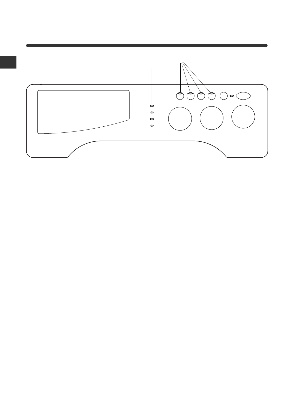
Washer-dryer description
GB
Control panel
Detergent dispenser
Leds
FUNCTION
Buttons
DRYING
Knob
ON-OFF/DOOR
LOCK
START/RESET
Button
TEMPERATURE
Knob
Led
ON-OFF
Button
Detergent dispenser: to add detergent and fabric
softener (see page 10).
LEDS: to find out which wash cycle phase is under
way.
If the Delay Timer function has been set, the time
left until the programme starts will be indicated (see
page 7).
DRYING knob: to set the desired drying cycle
(see page 9).
FUNCTION buttons: to select the functions
available. The button corresponding to the function
selected will remain on.
Note: to avoid excessive vibrations, before every spin cycle the machine distributes the load in a uniform manner
by continuously rotating the drum at a speed which is slightly faster than the normal washing speed.
When, despite repeated attempts, the load is still not evenly distributed, the machine spins at a lower speed than
the set frequency.
If the load is excessively unbalanced, the machine attempts to distribute it instead of spinning.
The balancing attempts may extend the total duration of the cycle, up to a maximum of 10 minutes.
TEMPERATURE knob: to set the temperature or
the cold wash cycle (see page 9).
START/RESET button: to start the programmes or
cancel any incorrect settings.
ON-OFF/DOOR LOCK Led: to find out whether the
Washer-dryer is on and if the appliance door can be
opened (see page 7).
ON/OFF button: to turn the Washer-dryer on and off.
PROGRAMME knob: to select the wash
programmes. The knob stays still during the cycle.
6
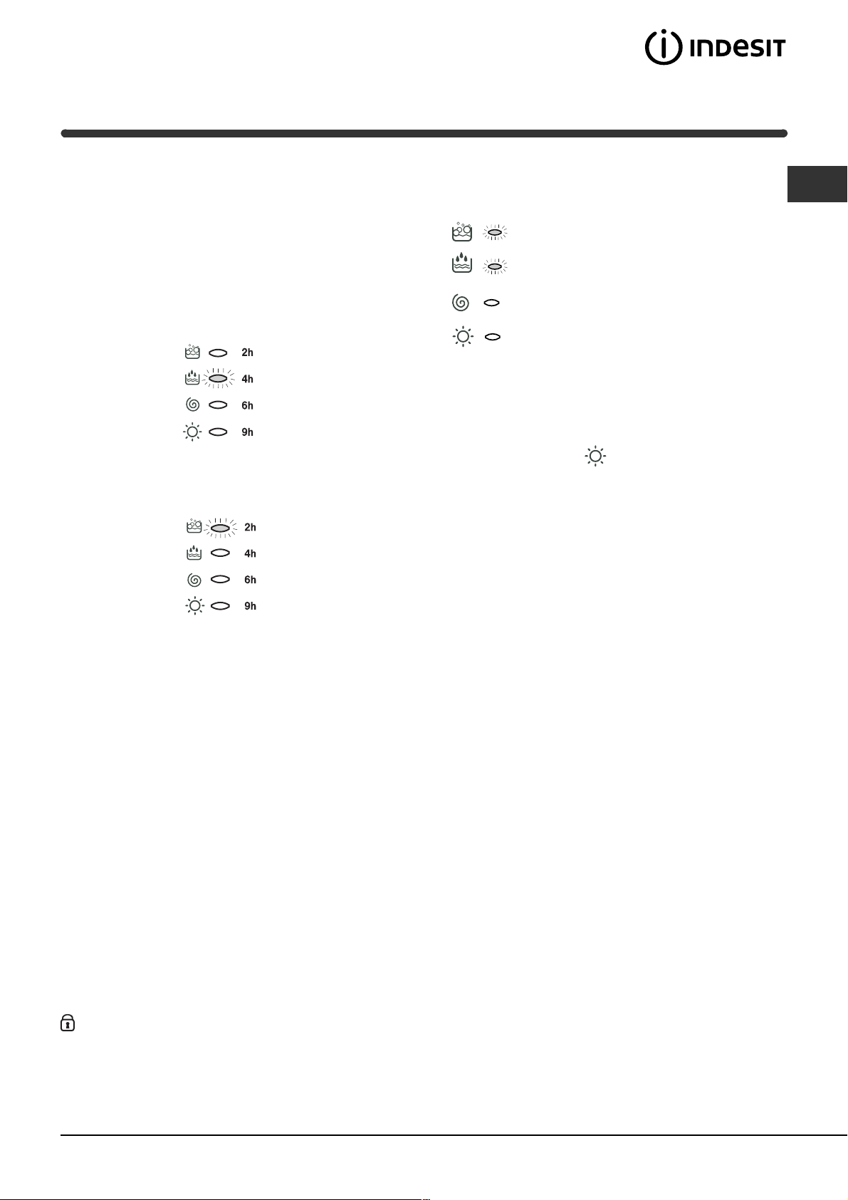
Leds
The LEDS provide important information.
This is what they can tell you:
Delay set:
If the Delay Timer function has been enabled (see
page. 9), once you have started the programme,
the LED corresponding to the delay set will begin to
flash:
As time passes, the remaining delay will be
displayed, and the corresponding LED will flash:
Once the set delay is complete, the flashing LED will
turn off and the programme set will start.
Cycle phase under way:
During the wash cycle, the LEDs gradually illuminate on to indicate the cycle phase under way:
Prewash / Wash
Rinse
Spin cycle
Drying
Note:
- during draining, the LED corresponding to the
Spin cycle phase will be turned on.
- when the drying cycle is complete, the indicator
light relative to phase
the DRYING knob needs to be set back to the 0
setting.
Function buttons
The FUNCTION BUTTONS also act like LEDS.
When a function is selected, the corresponding
button is illuminated.
If the function selected is incompatible with the
programme set, the button will flash and the
function will not be enabled.
If you set a function that is incompatible with
another function you selected previously, only the
last one selected will be enabled.
will flash, to indicate that
GB
ON-OFF/DOOR LOCK led
If this LED is on, the appliance door is locked to prevent it from being opened accidentally; to avoid any
damages, wait for the LED to flash before you open the appliance door.
The rapid flashing of the ON-OFF/DOOR LOCK Led together with the flashing of at least one other LED
indicates there is an abnormality (see page 13).
7
Starting and Programmes
GB
Briefly: starting a programme
1. Switch the Washer-dryer on by pressing button .
All the LEDS will light up for a few seconds and
the ON-OFF/DOOR LOCK Led will begin to flash.
2. Load your laundry into the washing machine and
shut the appliance door.
3. Set the PROGRAMME knob to the programme
required.
4. Set the wash temperature (see page 9).
5. Set the drying cycle if necessary (see page 9).
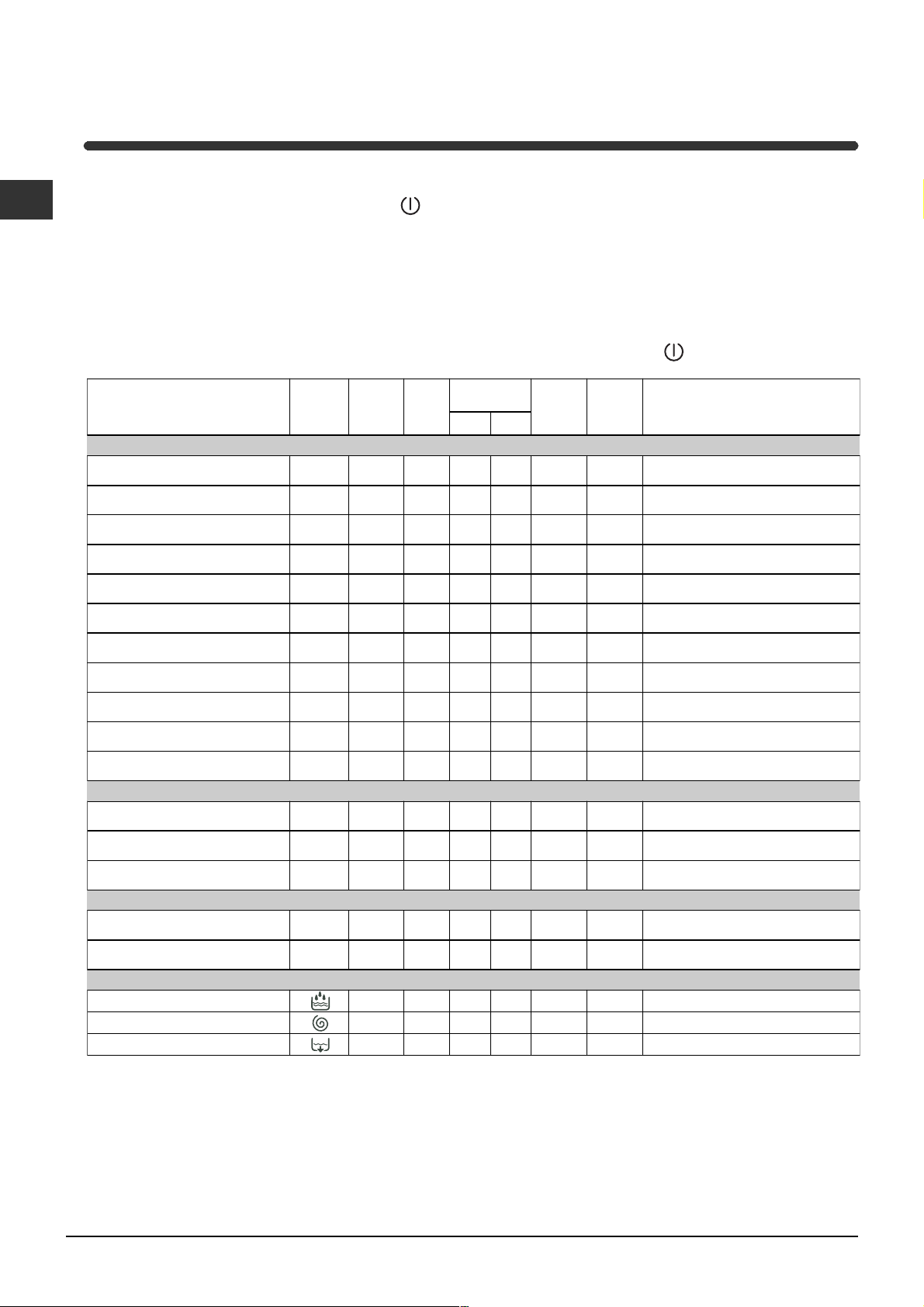
Programme table
Type of fabric and
degree of soil
Standard
Extremely soiled whites
Cotton:
(sheets, tablecloths, etc.)
Extremely soiled whites
Cotton:
(sheets, tablecloths, etc.)
Heavily soiled whites and
Cotton:
fast colours
Heavily soiled whites and
Cotton:
delicate colours
Slightly soiled whites and
Cotton:
delicate colou rs (shirts, jumpers, etc.)
Synthetics:
colours (baby linen, etc.)
Synthetics:
colours (baby linen, etc.)
Wool
Very delicate fabrics
(curtains, silk, viscose, etc.)
Drying cotton
Heavily soiled fast
Heavily soiled fast
Program.
Te m p e rature
1
2
2
2
3
4
4
5
6
7
Drying
Cyc le
90°C
90°C
60°C
40°C
40°C
°C
60
40°C
40°C
30°C
-
--
--
6. Add the detergent and any fabric softener (see page 10 ).
7. Start he programme by pressing the START/RESET
button.
To cancel it, keep the START/RESET button pressed
for at least 2 seconds.
8. When the programme is finished, the ON-OFF/
DOOR LOCK Led will flash to indicate that the
appliance door can be opened. Take out your
laundry and leave the appliance door ajar to allow
the drum to dry thoroughly. Turn the Washer-dryer
off by pressing button
Detergent
pre-
wash
-
-
-
-
-
-
-- - -
Fabric
softener
wash
Cycle
length
(mi nu tes )
155
150
140
125
85
83
70
50
45
.
Description of wash cycle
Pre-wash, wash cycle, rinse cycles,
intermediate an d final spin cycles
Wash cycle, rinse cycles,
intermediate an d final spin cycles
Wash cycle, rinse cycles,
intermediate an d final spin cycles
Wash cycle, rinse cycles,
intermediate an d final spin cycles
Wash cycle, rinse cycles,
intermediate an d final spin cycles
Wash cycle, rinse cycles, anti-crease
or delicate spin cycle
Wash cycle, rinse cycles, anti-crease
or delicate spin cycle
Wash cycle, rinse cyclese, delicate
spin cycle
Wash cycle, rinse cycles, anti-crease
or draining cycle
Drying delicates
8
-
-- - -
Tim e 4 you
Heavily soiled whites and
Cotton:
fast colours
Synthetics:
(all types of slightly soiled garments)
Synthetics:
(all types of slightly soiled garments)
Delicate colours
Delicate colours
10
11
9
60°C
°C
40
30°C
--
--
-
30
Wash cycle, rinse cycles,
60
intermediate an d final spin cycles
Wash cycle, rinse cycles, delicate
40
spin cycle
Wash cycle, rinse cycles and delicate
spin cycle
Sport
Sports shoes
Fabrics for sportswear
(Tracksuits, shorts, etc.)
PARTIAL PROGRAMMES
Rinse
Spin cycle
Drain
(MAX. 2 pairs)
12
13
°C
30
30°C
-
-
----- -
--
--
50
60
--
-- - -
Cold wash (without detergents), wash
cycle, rinse cycles, and delicate spin cycle
Wash cycle, rinse cycles,
intermediate an d final spin cycles
-
Rinse cycles and spin cycle
Draining and spin cycle
Drain
Notes
-For programme 9, we advise against exceeding a wash load of 3.5 kg.
-For programme 13 we advise against exceeding a wash load of 2 kg.
-For the anti-crease function: see Easy iron, opposite page. The information contained in the table is purely indicative.
Special programme
Daily (programme 11 for Synthetics) is designed to wash lightly soiled garments in a short amount of time: it only lasts
30 minutes and allows you to save on both time and energy. By setting this programme (11 at 30°C), you can wash
different fabrics together (except for woollen and silk items), with a maximum load of 3 kg.
We recommend the use of liquid detergent.
8
Personalisations
C
Setting the temperature
Turn the TEMPERATURE knob to set the wash temperature (see Programme table on page 8).
The temperature can be lowered, or even set to a cold wash (
Set the drying cycle
Turn the DRYING knob to set the desired drying type.
Two options are available:
A - Based on time: From 40 minutes to 180.
B - Based on the damp level of the dry clothes:
Iron
Hanger
Cupboard
and bathrobes.
A cooling stage is foreseen at the end of the drying cycle.
: slightly damp clothes, easy to iron.
: dry clothes to put away.
: very dry clothes, recommended for towelling
).
Table of drying times
Fabric
type
Cotton,
Linen
Cotton Terry towels
Ter i t al ,
Cotton
Acrylics Pyjamas, socks, etc.
Load type Max.
Clothing of different sizes
Sheets, Shirts
The data contained in the
table are purely indicative.
load
(kg) Cup-
5 180 170 140
5 180 170 140
2,5 140 120 100
170 6560
board
Hanger Iron
GB
If your laundry load to wash and dry is exceptionally in excess
Nylon Slips, tights, stockings, etc.
170 6560
of the maximum load foreseen (see table opposite), perform
the wash cycle, and when the programme is complete, divide up the garments and put part of them back in the
drum. Now follow the instructions provided for a dry only cycle. Repeat this procedure for the remainder of the load.
Dry only
Turn the PROGRAMME knob to one of the drying settings (7-8) depending on the type of fabric, then select the
desired drying type using the DRYING knob.
Important: - A spin cycle is carried out during the drying if you have set a cotton programme and a level of
dryness (Cupboard
, Hanger , Iron ).
- For cotton loads of less than 1 Kg, use the drying programme designed for delicate fabrics.
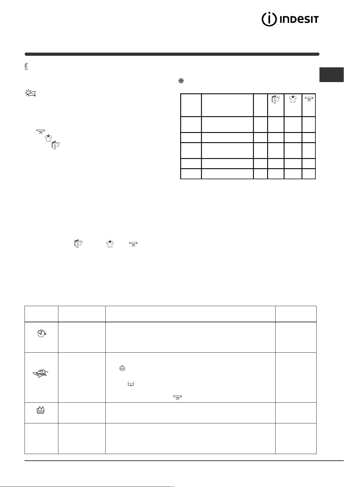
Functions
To enable a function:
1. press the button corresponding to the desired function, according to the table below;
2. the function is enabled when the corresponding button is illuminated.
Note: The rapid flashing of the button indicates that the corresponding function cannot be selected for the
programme set.
Function Effect Comments
Press the button repeatedly until the LED corresponding to the
Delays the start
of the wash by
up to 9 hours.
Delay Timer
desired delay is turned on.
The fifth time the button is pressed, the function will be disabled.
N.B.: Once you have pressed the Start/Reset button, the delay
can only be decreased if you wish to modify it.
Enabled with
programmes:
All
This option
reduces the
amount of
creasing on
fabrics, making
laundry left to soak (Anti-crease) and the Rinse cycle phase
LED will flash.
- to conclude the cycle, press the START/RESET button;
- to run the draining cycle alone, set the knob to the relative
symbol and press the START/RESET button.
3, 4, 6,
9, 10,
Rinse cycle.
them easier to
When this function is set, programmes 4, 6 will end with the
Easy iron
Extra Rin se
iron.
Increases the
efficiency of the
rinse.
If you also want to run the drying cycle, this button is enabled
only if combined with level (Iron).
Recommended when the appliance has a full load or with large
quantities of detergent.
1, 2, 3, 4, 9,
10, 12, 13,
Rinse cycle.
All
Reduces the
spin speed.
1200-600
programmes
except for 6,
7, 8 and
draining.
9
 Loading...