

INDESIT IS50E(W) User Manual
GB
Operating Instructions
Contents
GB
Installation, 1-3
English, 1
Positioning and levelling
Electrical connection
Table of characteristics
Description of the appliance, 4
Overall view
Control panel
COOKER AND OVEN
IS50E
IS50E1
Start-up and use, 5
Using the oven
Cooking modes
Practical cooking advice
Oven cooking advice table
Using the electric hob, 7
Switching the cooking zones on and off
Cooking zones
Precautions and tips, 9
General safety
Disposal
Respecting and conserving the environment
Maintenance and care, 10
Switching the appliance off
Cleaning the appliance
Replacing the oven light bulb
Cleaning the hob
Assistance
You must read these instructions prior to using
your appliance and retain them for future use.
Installation
GB
! Before operating your new appliance please read
this instruction booklet carefully. It contains
important information concerning the safe installation
and operation of the appliance.
! Please keep these operating instructions for future
reference. Make sure that the instructions are kept
with the appliance if it is sold, given away or moved.
! The appliance must be installed by a qualified
professional according to the instructions provided.
! Any necessary adjustment or maintenance must be
performed after the cooker has been disconnected
from the electricity supply.
Positioning and levelling
! It is possible to install the appliance alongside
cupboards whose height does not exceed that of the
hob surface.
! Make sure that the wall in contact with the beck of
the appliance is made from a non-flammable, heatresistant material (T 90°C).
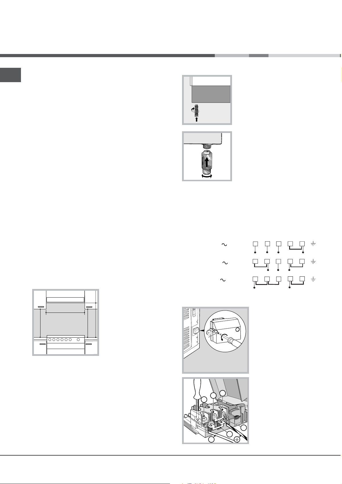
Levelling
If it is necessary to level the
appliance, screw the
adjustable feet into the places
provided on each corner of the
base of the cooker (
figure
).
see
The legs* fit into the slots on
the underside of the base of
the cooker.
Electrical connection
Fitting the power supply cable
The cable should be suited to the type of electrical
connection used, according to the following
connection diagram:
To install the appliance correctly:
• Place it in the kitchen, dining room or the bed-sit
(not in the bathroom).
• If the top of the hob is higher than the cupboards,
the appliance must be installed at least 200 mm
away from them.
• If the cooker is
installed underneath a
wall cabinet, there must
be a minimum distance
of 420 mm between this
cabinet and the top of
mm. with hood
mm. without hood
650
the hob.
700
min.
min.
This distance should be
mm.
420
Min.
HOOD
Min. mm.
600
420
Min. mm.
increased to 700 mm if
the wall cabinets are
flammable (
see figure
).
• Do not position blinds behind the cooker or less
than 200 mm away from its sides.
• Any hoods must be installed according to the
instructions listed in the relevant operating manual.
H05RR-F 5x2.5 CEI-UNEL 35363
400 3N
400V 2N
H05RR-F 4x4 CEI-UNEL 35363
230V
H05RR-F 3x4 CEI-UNEL 35363
1 2
R
12345
1
R
3
T
S
R
S
3
2
To install the power supply cable correctly:
1. Loosen the screw V
in the terminal board
and pull the cover to
V
open it (
see figure
2. Position the
connection supports A
see figure
3
2
1
(
to the connection
) according
diagram shown above.
The terminal board is
designed for singlephase 230 V
B
N
A
connection: terminals 1,
2 and 3 are connected
4
5
N
N
4
5
N
).
2
to each other; jumper 4-5 is located in the lower area
of the terminal board.
3. Position the wires N and
diagram (
see figure
) and proceed with the
66
as shown in the
6
66
connection process, tightening the terminal screws
as far as possible.
4. Position the remaining wires on terminals 1-2-3
and tighten the screws.
5. Fix the power supply cable in place by fastening
the cable clamp screw.
6. Close the terminal board cover by tightening the
screws V.
Connecting the supply cable to the mains
Install a standardised plug corresponding to the
load indicated on the appliance data plate (
Technical data table
).
see
The appliance must be directly connected to the mains
using an omnipolar circuit-breaker with a minimum
contact opening of 3 mm installed between the
appliance and the mains. The circuit-breaker must be
suitable for the charge indicated and must comply with
NFC 15-100 regulations (the earthing wire must not be
interrupted by the circuit-breaker). The supply cable
must be positioned so that it does not come into
contact with temperatures higher than 50°C at any point.
Before connecting the appliance to the power
supply, make sure that:
• The appliance is earthed and the plug is compliant
with the law.
• The socket can withstand the maximum power of
the appliance, which is indicated by the data
plate.
• The voltage is in the range between the values
indicated on the data plate.
• The socket is compatible with the plug of the
appliance. If the socket is incompatible with the
plug, ask an authorised technician to replace it.
Do not use extension cords or multiple sockets.
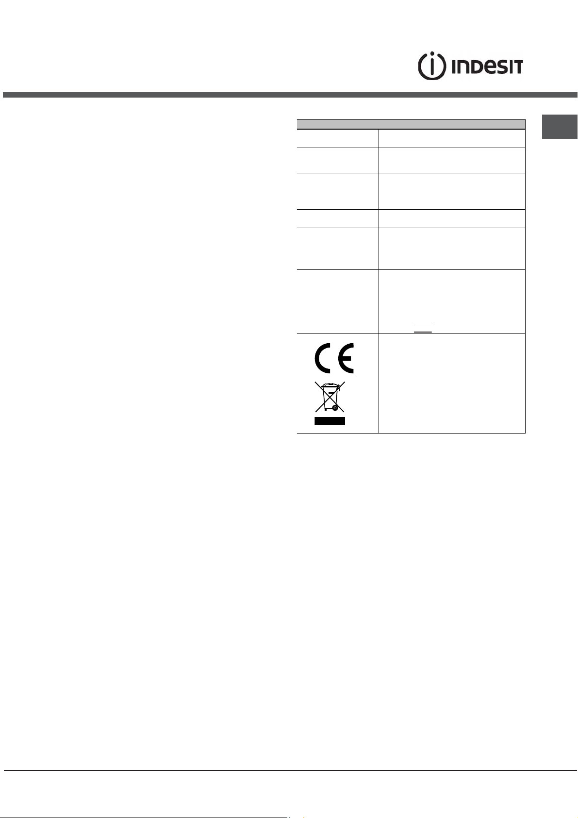
TABLE OF CHARACTERISTSICS
Dimensions
Oven HxDxW
Volume
Useful
measurements
relating to the oven
compartment
Voltage and
frequency
Electric Hob
ENERGY LABEL
This appliance conforms to the following
34x39x44
58 l
width 42 cm
depth 44 cm
height 18 cm
see data plate
Rapid Ø 180 mm: 2000 W
Rapid Ø 145 mm: 1500 W
Max. Hob Power Absorpt ion: 7000 W
Directive 2002/40/ EC on t he la bel of
electric ovens.
Standard EN 50304
Energy consumpt ion for Natur al
convection – heating m ode: Static
mode;
European Economic Community
directives: 200 6/95 /E C dat ed 12/12/06
(Low Voltage) and subsequent
amendments - 04/108/EC dated
15/12/04 (Electrom agnetic
Compatibility) and subsequent
amendments - 93/68/ EE C dated
22/07/93 and subseq uent am endments.
2002/96/EEC
1275/2008 (Stand-by/ Off mo de)
GB
! Once the appliance has been installed, the power
supply cable and the electrical socket must be
easily accessible.
! The cable must not be bent or compressed.
! The cable must be checked regularly and replaced
by authorised technicians only.
! The manufacturer declines any liability should
these safety measures not be observed.
3
GB
Description
of the appliance
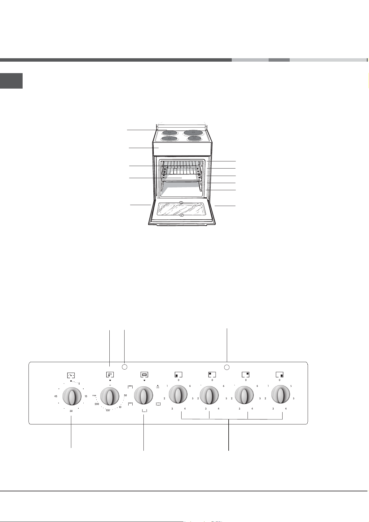
Overall view
Electric hob
DRIPPING PAN
Control panel
Control panel
GRILL rack
Adjustable foot
GUIDE RAILS
for the sliding racks
position 5
position 4
position 3
position 2
position 1
Adjustable foot
THERMOSTAT
knob
Timer knob*
Only available in certain models.
*
4
THERMOSTAT
indicator light
PROGRAMMER
knob
ACTIVE HOTPLATE
indicator light
ACTIVE HOTPLATE
knobs
 Loading...