

Image 9.5, IMEL3906.0 User Manual
Model No, IMEL3906.0
Serial No,
Write the serial number in the
space above for reference.
oooo_
ooooo
Serial . '_
QUESTIONS?
As a manufacturer, we are commit-
ted to providing complete customer
satisfaction. If you have questions,
or if parts are damaged or missing,
PLEASE DO NOT CONTACT THE
STORE; please contact Customer
Care.
IMPORTANT: You must note the
product model number and serial
number (see the drawing above)
before contacting us:
USER'S MANUAL
CALL TOLL-FREE:
1-800-753-4645
Mon,-Fri, 6 a,m,-6 p,m, MST
Sat, 8 a.m,-4 p.m, MST
ON THE WEB:
www.imageservice.com
www.imagefitness.com
new products, prizes,
fitness tips, and much more!
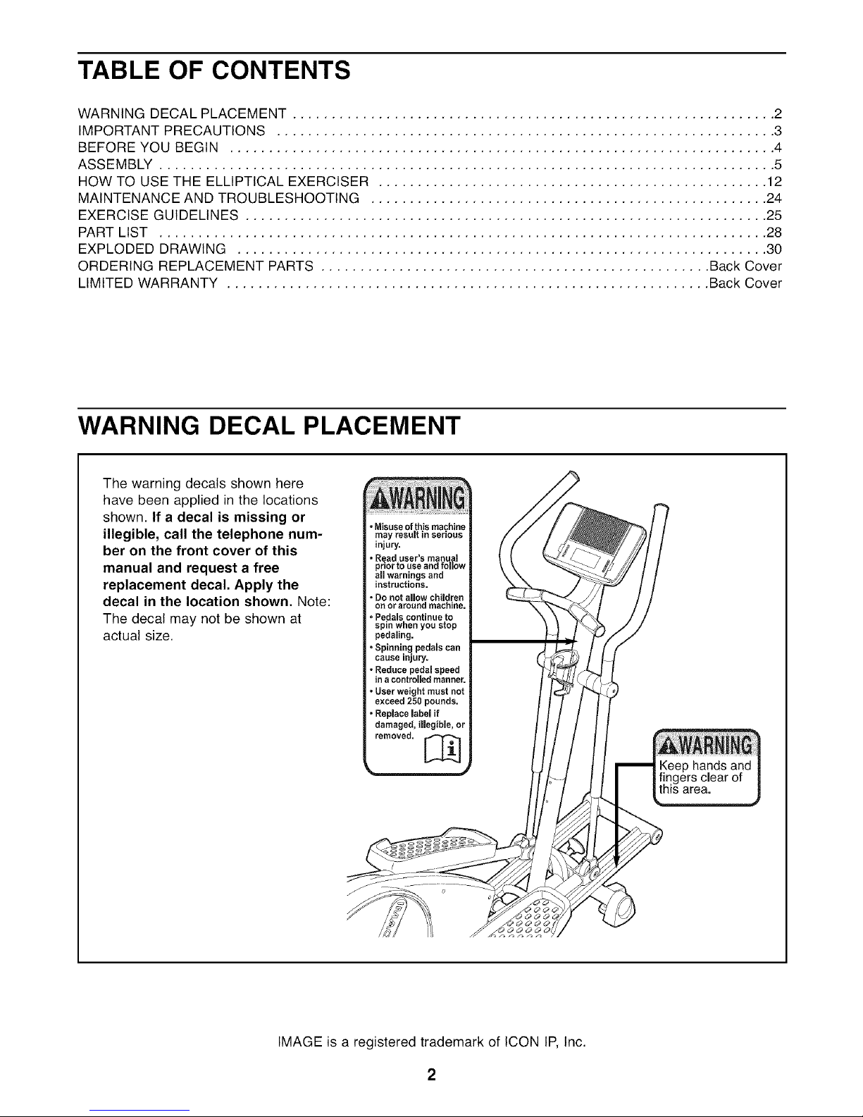
TABLE OF CONTENTS
WARNING DECAL PLACEMENT .............................................................. 2
IMPORTANT PRECAUTIONS ................................................................ 3
BEFORE YOU BEGIN ...................................................................... 4
ASSEMBLY ............................................................................... 5
HOW TO USE THE ELLIPTICAL EXERClSER .................................................. 12
MAINTENANCE AND TROUBLESHOOTING ................................................... 24
EXERCISE GUIDELINES ................................................................... 25
PART LIST .............................................................................. 28
EXPLODED DRAWING .................................................................... 30
ORDERING REPLACEMENT PARTS .................................................. Back Cover
LIMITED WARRANTY .............................................................. Back Cover
WARNING DECAL PLACEMENT
The warning decals shown here
have been applied in the locations
shown. If a decal is missing or
illegible, call the telephone num-
ber on the front cover of this
manual and request a free
replacement decal. Apply the
decal in the location shown. Note:
The decal may not be shown at
actual size.
IMAGE is a registered trademark of ICON IP, Inc.
2
IMPORTANT PRECAUTIONS
BEFORE YOU BEGIN
Thank you for selecting the new IMAGE _ 9.5 elliptical
exerciser. The iMAGE 9.5 is an incredibly smooth
exerciser that moves your feet in a natural elliptical
path, minimizing the impact on your knees and ankles.
Welcome to a whole new world of natural, elliptical-
motion exercise.
For your benefit, read this manual carefully before
you use the exercise cycle, If you have questions
after reading this manual, please see the front cover
of this manual. To help us assist you, note the product
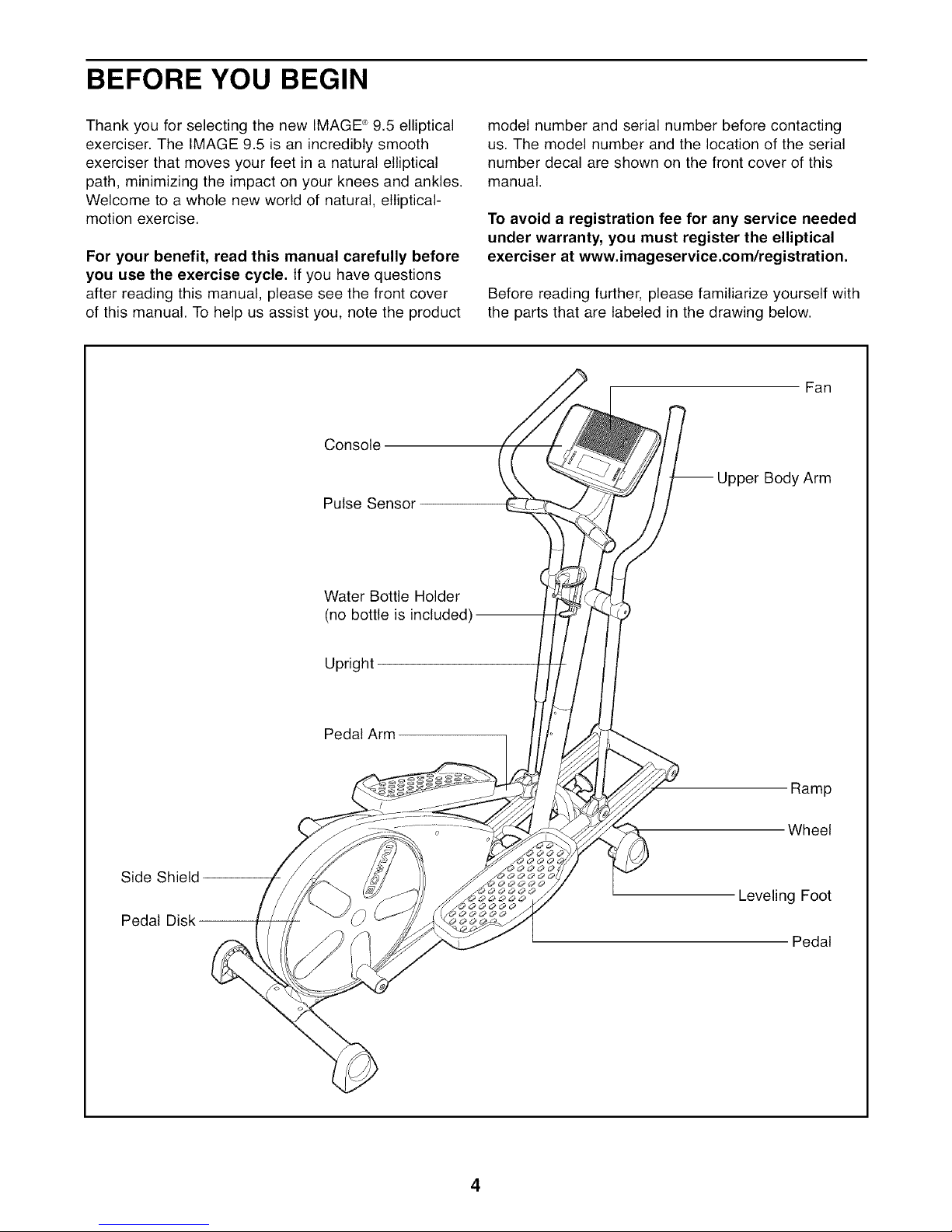
Console
Pulse Sensor
model number and serial number before contacting
us. The model number and the location of the serial
number decal are shown on the front cover of this
manual.
To avoid a registration fee for any service needed
under warranty, you must register the elliptical
exerciser at www, imageservice,com/registration,
Before reading further, please familiarize yourself with
the parts that are labeled in the drawing below.
Fan
I_ Upper Body Arm
Side Shield
Pedal Disk
Water Bottle Holder
(no bottle is included)
Upright
Pedal Arm
Ramp
Wheel
Leveling Foot
Pedal

ASSEMBLY
To hire an authorized service technician to assemble the elliptical exerciser, call 1-800-445-2480.
Assembly requires two persons. Place all parts of the elliptical exerciser in a cleared area and remove all
packing materials; do not dispose of the packing materials until assembly is completed. Assembly requires the
included hex keys and your own adjustable wrench ___, Phillips screwdriver _,
and rubber mallet c__ _J
As you assemble the elliptical exerciser, use the drawings below to identify small parts. The number in parenthe-
ses below each drawing is the key number of the part, from the PART LIST near the end of this manual. The
number following the parentheses is the quantity needed for assembly. Note: Some small parts may have
been preassembled. If a part is not in the parts bag, check to see if it has been preassembled.
Star Washer M8 Washer M8 Large Wave Washer Large Wave
(85)-6 (64)-4 Washer (81)-2 (27)-2 Washer (20)-2
M8 Nylon M10 Nylon Round Head M4 x 19mm M4 x 22mm M8 x 25mm Patch
Locknut (87)-2 Locknut (84)-4 Screw (93)-4 Screw (68)-6 Screw (66)-2 Screw (70)-6
M8 x 69mm Button Bolt (91)-2 M10 x 77mm Carriage Bolt (58)-4
M8 Split
Washer (95)-2
M4 x 16mm
M8 x 63mm Bolt Set (67)-2
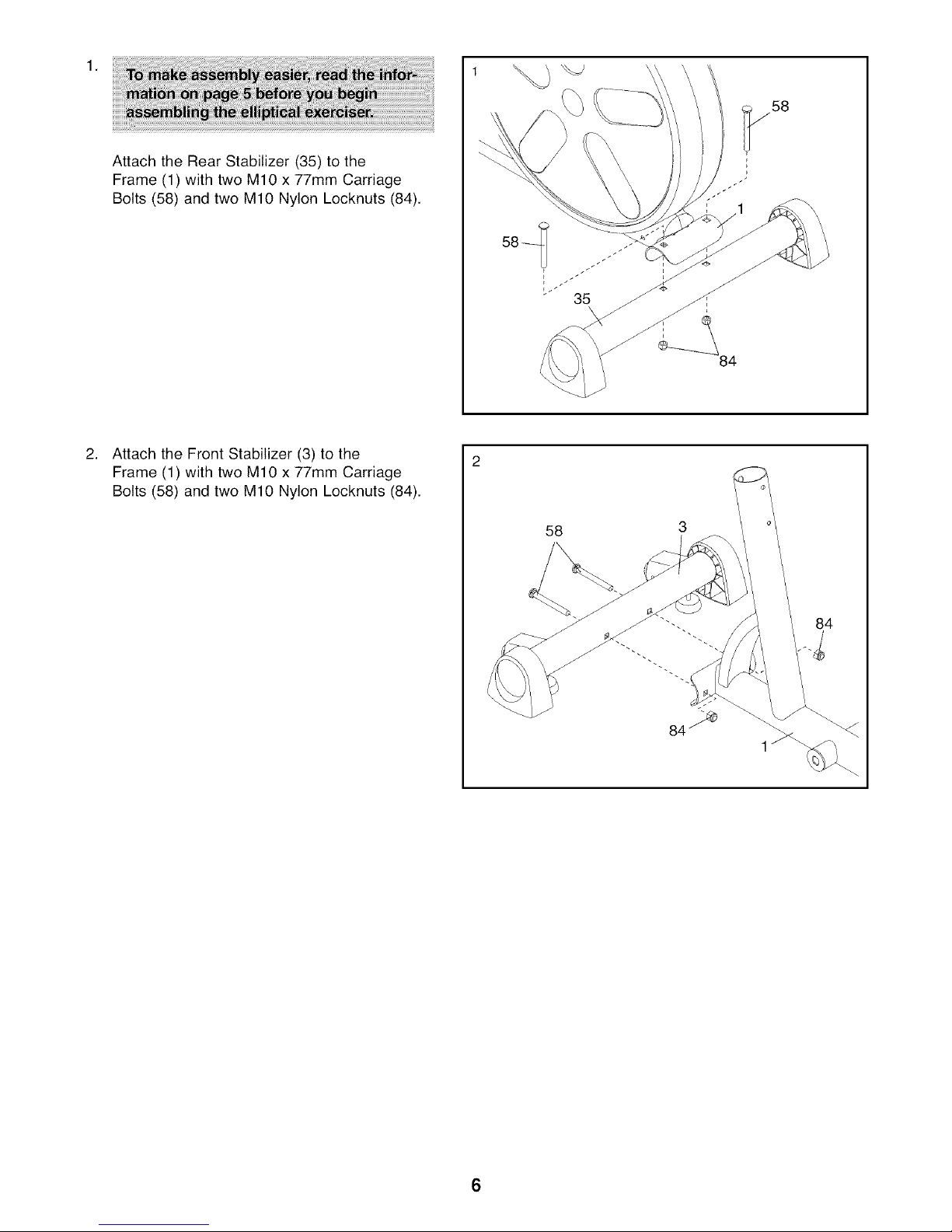
1,
Attach the Rear Stabilizer (35) to the
Frame (1) with two M10 x 77mm Carriage
Bolts (58) and two M10 Nylon Locknuts (84).
Attach the Front Stabilizer (3) to the
Frame (1) with two M10 x 77mm Carriage
Bolts (58) and two M10 Nylon Locknuts (84).
58 3
84
6
.
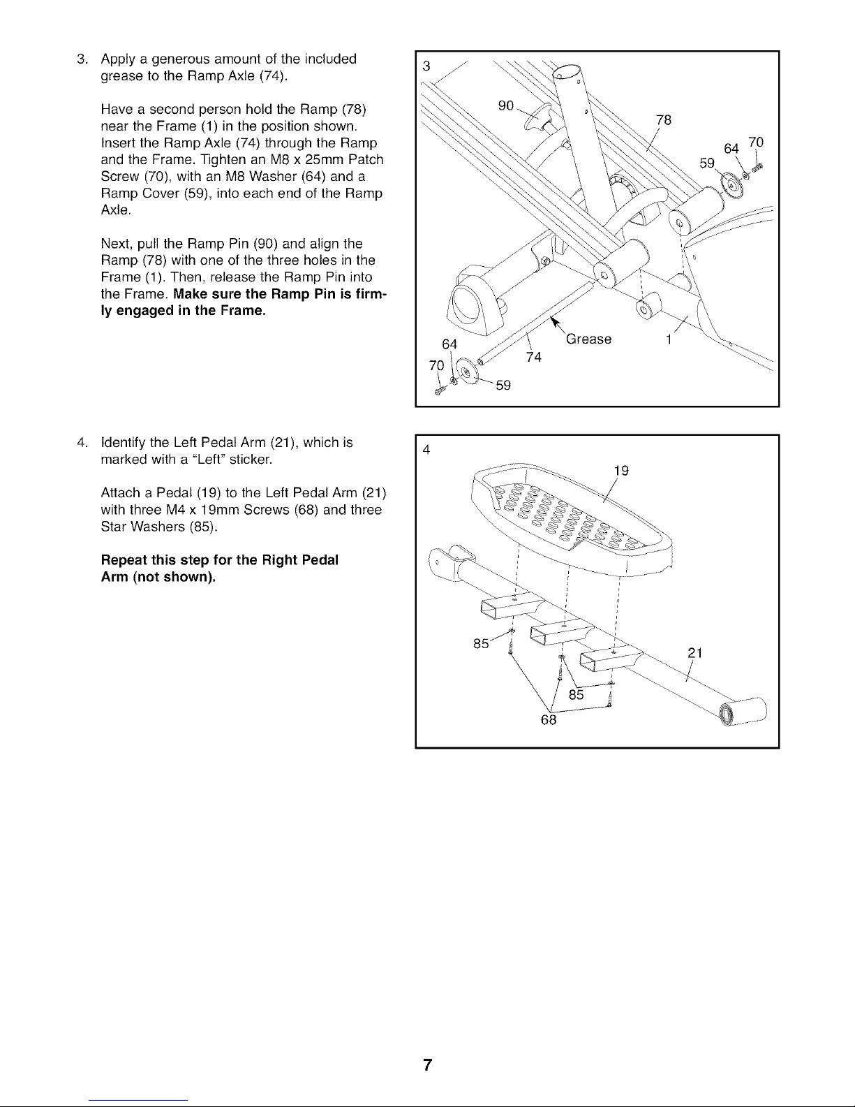
Apply a generous amount of the included
grease to the Ramp Axle (74).
Have a second person hold the Ramp (78)
near the Frame (1) in the position shown.
Insert the Ramp Axle (74) through the Ramp
and the Frame. Tighten an M8 x 25mm Patch
Screw (70), with an M8 Washer (64) and a
Ramp Cover (59), into each end of the Ramp
Axle.
Next, pull the Ramp Pin (90) and align the
Ramp (78) with one of the three holes in the
Frame (1). Then, release the Ramp Pin into
the Frame. Make sure the Ramp Pin is firm-
ly engaged in the Frame.
Identify the Left Pedal Arm (21), which is
marked with a "Left" sticker.
Attach a Pedal (19) to the Left Pedal Arm (21)
with three M4 x 19mm Screws (68) and three
Star Washers (85).
78
64
59
64
74
59
19
Repeat this step for the Right Pedal
Arm (not shown),
\
21
85
68
7
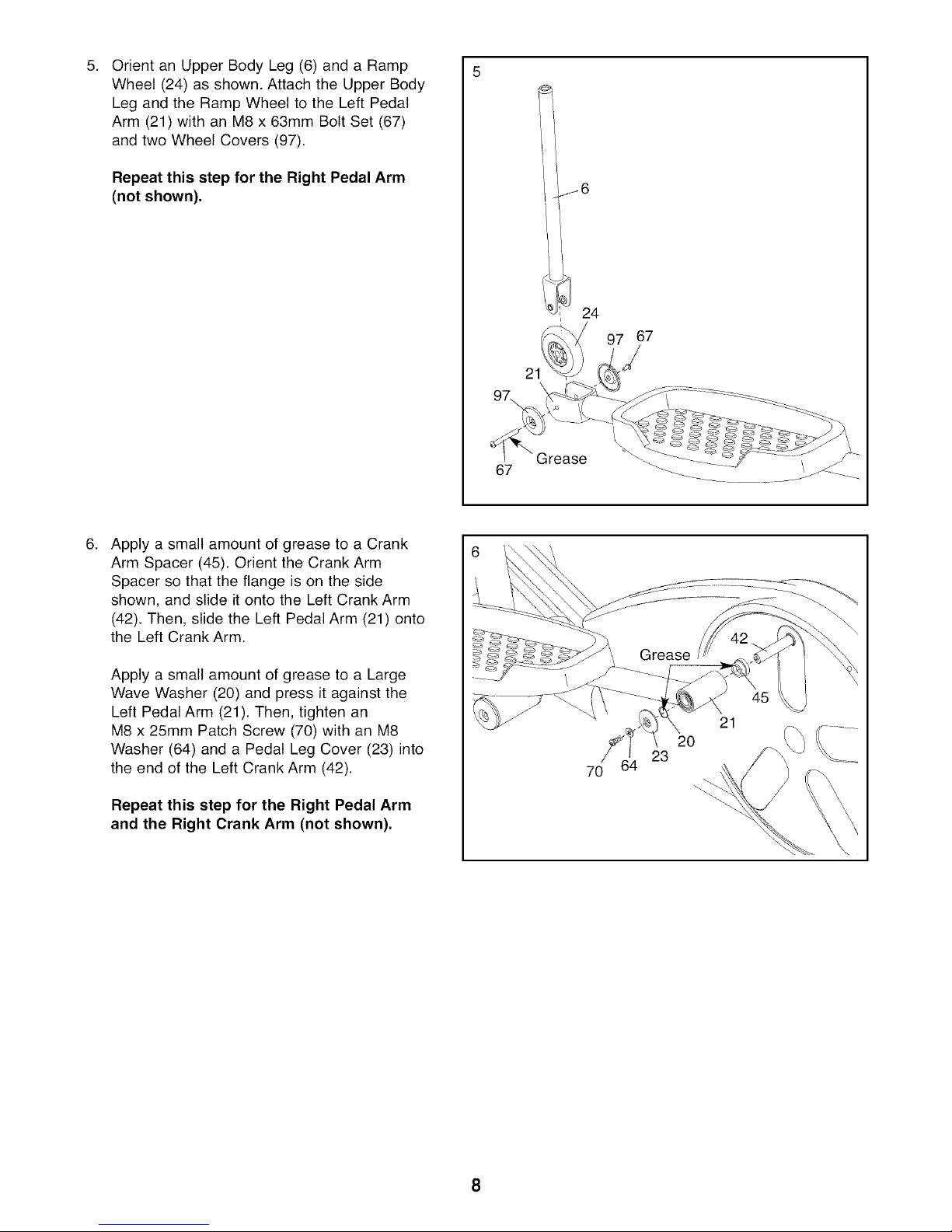
Orient an Upper Body Leg (6) and a Ramp
5. 5
Wheel (24) as shown. Attach the Upper Body
Leg and the Ramp Wheel to the Left Pedal
Arm (21) with an M8 x 63mm Bolt Set (67)
and two Wheel Covers (97).
Repeat this step for the Right Pedal Arm
(not shown),
.
Apply a small amount of grease to a Crank
Arm Spacer (45). Orient the Crank Arm
Spacer so that the flange is on the side
shown, and slide it onto the Left Crank Arm
(42). Then, slide the Left Pedal Arm (21) onto
the Left Crank Arm.
67
21
Grease
j6
I
24
67
/
Apply a small amount of grease to a Large
Wave Washer (20) and press it against the
Left Pedal Arm (21). Then, tighten an
M8 x 25mm Patch Screw (70) with an M8
Washer (64) and a Pedal Leg Cover (23) into
the end of the Left Crank Arm (42).
Repeat this step for the Right Pedal Arm
and the Right Crank Arm (not shown),
21
20
23
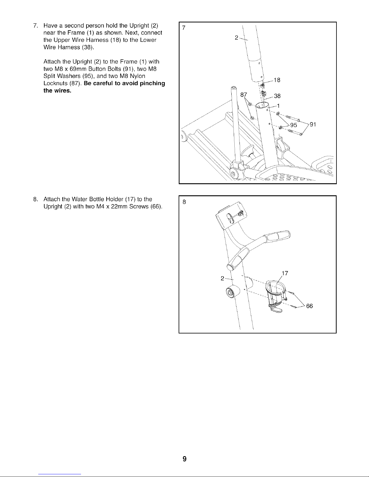
7,
Have a second person hold the Upright (2)
near the Frame (1) as shown. Next, connect
the Upper Wire Harness (18) to the Lower
Wire Harness (38).
Attach the Upright (2) to the Frame (1) with
two M8 x 69mm Button Bolts (91), two M8
Split Washers (95), and two M8 Nylon
Locknuts (87). Be careful to avoid pinching
the wires.
Attach the Water Bottle Holder (17) to the
Upright (2) with two M4 x 22mm Screws (66).
87
17
66
9
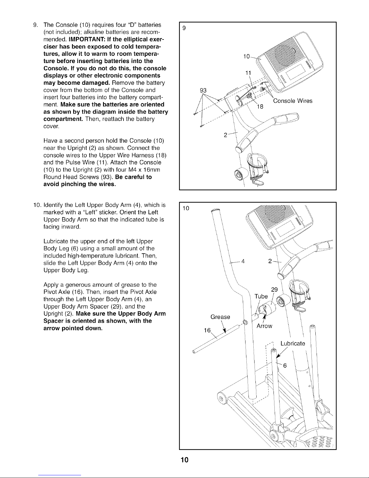
The Console (10) requires four "D" batteries
9. 9
(not included); alkaline batteries are recom-
mended. IMPORTANT: If the elliptical exer-
ciser has been exposed to cold tempera-
tures, allow it to warm to room tempera-
ture before inserting batteries into the
Console. If you do not do this, the console
displays or other electronic components
may become damaged. Remove the battery
cover from the bottom of the Console and
insert four batteries into the battery compart-
ment. Make sure the batteries are oriented
as shown by the diagram inside the battery
compartment. Then, reattach the battery
cover.
Have a second person hold the Console (10)
near the Upright (2) as shown. Connect the
console wires to the Upper Wire Harness (18)
and the Pulse Wire (11). Attach the Console
(10) to the Upright (2) with four M4 x 16mm
Round Head Screws (93). Be careful to
avoid pinching the wires.
11
93
Console Wires
18
10. Identify the Left Upper Body Arm (4), which is
marked with a "Left" sticker. Orient the Left
Upper Body Arm so that the indicated tube is
facing inward.
Lubricate the upper end of the left Upper
Body Leg (6) using a small amount of the
included high-temperature lubricant. Then,
slide the Left Upper Body Arm (4) onto the
Upper Body Leg.
Apply a generous amount of grease to the
Pivot Axle (16). Then, insert the Pivot Axle
through the Left Upper Body Arm (4), an
Upper Body Arm Spacer (29), and the
Upright (2). Make sure the Upper Body Arm
Spacer is oriented as shown, with the
arrow pointed down.
10
29
Grease _.
Lubricate
10
 Loading...