


Reach Ins
Installation, Operation and Maintenance Manual
Please read this manual completely before attempting to install or operate this equipment. Notify carrier of damage! Inspect all components immediately. See page 2.
IMPORTANT INFORMATION
READ BEFORE USE
PLEASE SAVE THESE INSTRUCTIONS!

|
Service and Installation Manual |
CONTENTS |
|
RECEIVING & INSPECTING EQUIPMENT |
..................................................................................2 |
SPECIFICATIONS .......................................................................................................................................... |
3 |
INSTALLATION .................................................................................................................................... |
4 |
OPERATION…....................................................................................................................................................... |
5 |
MAINTENANCE .......................................................................................................................... |
7 |
WIRING DIAGRAM ....................................................................................................... |
9 |
All rights reserved. Reproduction without written permission is prohibited.
SERIAL NUMBER INFORMATION
The serial number of all self-contained refrigerators and freezers is located inside the unit on the left hand side near the top on the wall.
Always have the serial number of your unit available when calling for parts or service.
This manual covers standard units only. If you have a custom unit, consult the Technical Support Department at 1-888-275-4538; 514-737-9701.
RECEIVING AND INSPECTING THE EQUIPMENT
Even though most equipment is shipped crated, care should be taken during unloading so the equipment is not damaged while being moved into the building.
1.Visually inspect the exterior of the package and skid or container. Any damage should be noted on the delivery slip and reported to MVP Group immediately at 1-888-275-4538; 514-737-9701.
2.If damaged, open and inspect the contents with the carrier.
3.WITHIN 48 HOURS OF RECEIPT: In the event that the exterior is not damaged, yet upon opening, there is concealed damage to the equipment, notify MVP Group immediately at 1-888-275-4538; 514-737-9701.
4.Be certain to check the compressor compartment housing and visually inspect the refrigeration package. Be sure lines are secure and base is still intact.
5.Retain all crating material until an inspection has been made or waived.
2

Service and InstallationManual
SPECIFICATIONS
|
|
SOLID DOOR REFRIGERATORS |
|
|
|
|
|
|
|
|
|
|
|
|
|
|
|
|
|
|
||||||||||||
|
|
|
|
|
|
|
|
|
|
|
|
|
|
|
|
|
|
|
|
|
|
|
|
|
|
|
|
|
|
|
|
|
|
|
|
|
|
|
|
|
|
|
|
|
|
STORAGE |
|
|
|
SHELF |
|
|
|
|
|
|
|
SHIP |
|
|
|
||||
|
|
|
|
|
|
|
|
|
|
|
|
|
CAPACITY |
|
|
|
CAPACITY |
|
|
|
|
CHARGE |
|
WEIGHT |
|
NEMA |
|
|||||
|
|
MODEL# |
|
V/Hz/Ph |
|
|
AMPS |
Cu-ft |
|
HP |
|
Sq-ft |
|
BTU |
|
OZ |
|
LBS |
|
PLUG |
|
|||||||||||
|
|
KB27R |
|
115/60/1 |
|
6 |
|
|
23 |
|
|
3/8 |
|
14.0 |
|
3200 |
|
12.0 |
|
350 |
|
|
5-15P |
|
||||||||
|
|
|
|
|
|
|
|
|
|
|
|
|
|
|
|
|
|
|
|
|
|
|
|
|
|
|
|
|
|
|
|
|
|
|
KB54R |
|
115/60/1 |
|
9 |
|
|
49 |
|
|
1/2 |
|
28.1 |
|
5800 |
|
18.7 |
|
518 |
|
|
5-15P |
|
||||||||
|
|
|
|
|
|
|
|
|
|
|
|
|
|
|
|
|
|
|
|
|
|
|
|
|
|
|
|
|
|
|
|
|
|
|
|
|
|
|
|
|
|
|
|
|
|
|
|
|
|
|
|
|
|
|
|
|
|
|
|
|
|
|
|
|
|
|
|
KB81R |
|
115/60/1 |
|
10 |
|
|
72 |
|
|
3/4 |
|
42.1 |
|
7625 |
|
21.2 |
|
669 |
|
|
5-15P |
|
||||||||
|
|
|
|
|
|
|
|
|
|
|
|
|
|
|
|
|
|
|
|
|
|
|
|
|
|
|
|
|
|
|
|
|
|
|
|
|
|
|
|
|
|
|
|
|
|
|
|
|
|
|
|
|
|
|
|
|
|
|
|
|
|
|
|
||
|
|
GLASS DOOR REFRIGERATORS |
|
|
|
|
|
|
|
|
|
|
|
|
|
|
|
|
|
|
||||||||||||
|
|
|
|
|
|
|
|
|
|
|
|
|
|
|
|
|
|
|
|
|
|
|
|
|
|
|
|
|
|
|
|
|
|
|
|
|
|
|
|
|
|
|
|
|
|
STORAGE |
|
|
|
SHELF |
|
|
|
|
|
|
|
SHIP |
|
|
|
||||
|
|
|
|
|
|
|
|
|
|
|
|
|
CAPACITY |
|
|
|
CAPACITY |
|
|
|
|
CHARGE |
|
WEIGHT |
|
NEMA |
|
|||||
|
|
MODEL# |
|
V/Hz/Ph |
|
|
AMPS |
Cu-ft |
|
HP |
|
Sq-ft |
|
BTU |
|
OZ |
|
LBS |
|
PLUG |
|
|||||||||||
|
|
|
|
|
|
|
|
|
|
|
|
|
|
|
|
|
|
|
|
|
|
|
|
|
|
|
|
|
||||
|
|
KB27RG |
|
115/60/1 |
|
6 |
|
|
23 |
|
|
3/8 |
|
14.0 |
|
3200 |
|
12.0 |
|
350 |
|
|
5-15P |
|
||||||||
|
|
|
|
|
|
|
|
|
|
|
|
|
|
|
|
|
|
|
|
|
|
|
|
|
|
|
|
|
|
|
|
|
|
|
KB54RG |
|
115/60/1 |
|
9 |
|
|
49 |
|
|
1/2 |
|
28.1 |
|
5800 |
|
18.7 |
|
518 |
|
|
5-15P |
|
||||||||
|
|
|
|
|
|
|
|
|
|
|
|
|
|
|
|
|
|
|
|
|
|
|
|
|
|
|
|
|
|
|
||
|
|
|
|
|
|
|
|
|
|
|
|
|
|
|
|
|
|
|
|
|
|
|
|
|
|
|
|
|||||
|
SOLID DOOR FREEZERS |
|
|
|
|
|
|
|
|
|
|
|
|
|
|
|
|
|
|
|
|
|||||||||||
|
|
|
|
|
|
|
|
|
|
|
|
|
|
|
|
|
|
|
|
|
|
|
|
|
|
|
|
|
|
|
|
|
|
|
|
|
|
|
|
|
|
|
|
|
STORAGE |
|
|
|
|
SHELF |
|
|
|
|
|
|
|
SHIP |
|
|
|
||||
|
|
|
|
|
|
|
|
|
|
|
|
CAPACITY |
|
|
|
|
CAPACITY |
|
|
|
|
CHARGE |
|
WEIGHT |
|
NEMA |
|
|||||
|
|
MODEL# |
V/Hz/Ph |
|
AMPS |
|
Cu-ft |
|
HP |
|
Sq-ft |
|
BTU |
|
OZ |
|
LBS |
|
PLUG |
|
||||||||||||
|
|
KB27F |
115/60/1 |
|
|
11 |
|
|
23 |
|
5/8 |
|
|
14.0 |
|
|
2325 |
|
|
14.1 |
|
|
364 |
|
|
5-15P |
|
|||||
|
|
|
|
|
|
|
|
|
|
|
|
|
|
|
|
|
|
|
|
|
|
|
|
|
|
|
|
|
||||
|
|
KB54F |
115/60/1 |
|
|
12 |
|
|
49 |
|
1 |
|
|
28.1 |
|
|
3650 |
|
|
25 |
|
|
568 |
|
|
5-15P |
|
|||||
|
|
|
|
|
|
|
|
|
|
|
|
|
|
|
|
|
|
|
|
|
|
|
|
|
|
|
|
|||||
|
|
|
|
|
|
|
|
|
|
|
|
|
|
|
|
|
|
|
|
|
|
|
|
|||||||||
SOLID DOOR FREEZERS |
|
|
|
|
|
|
|
|
|
|
|
|
|
|
|
|
|
|
|
|
||||||||||||
|
|
|
|
|
|
|
|
|
|
|
|
|
|
|
|
|
|
|
|
|
|
|
|
|
|
|
|
|
|
|
||
|
|
|
|
|
|
|
|
|
|
|
STORAGE |
|
|
|
|
|
SHELF |
|
|
|
|
|
|
|
|
SHIP |
|
|
|
|
||
|
|
|
|
|
|
|
|
|
|
|
CAPACITY |
|
|
|
|
CAPACITY |
|
|
|
|
CHARGE |
|
|
WEIGHT |
|
NEMA |
|
|||||
|
MODEL# |
|
V/Hz/Ph |
AMPS |
|
Cu-ft |
|
HP |
|
|
Sq-ft |
|
|
BTU |
|
|
OZ |
|
|
LBS |
|
PLUG |
|
|||||||||
|
KB81FDV |
|
115/208~ |
|
|
16 |
|
|
72 |
|
1-1/4 |
|
42.1 |
|
4500 |
|
28.9 |
|
776 |
|
|
L14-20P |
|
|||||||||
|
|
230/60/1 |
|
|
|
|
|
|
|
|
|
|
|
|
||||||||||||||||||
|
|
|
|
|
|
|
|
|
|
|
|
|
|
|
|
|
|
|
|
|
|
|
|
|
|
|
|
|
|
|
||
|
|
|
|
|
|
|
|
|
|
|
|
|
|
|
|
|
|
|
|
|
|
|
|
|
|
|
|
|
|
|
|
|
3

Service and Installation Manual
INSTALLATION
Location
Units represented in this manual are intended for indoor use only. Be sure the location chosen has a floor strong enough to support the total weight of the cabinet and contents. A fully loaded unit can weigh as much as 1500 pounds. Reinforce the floor as necessary to provide for maximum loading. For the most efficient refrigeration, be sure to provide good air circulation inside and out.
Inside Cabinet
Do not pack the units so full that air cannot circulate. The refrigerated air is discharged at the top rear of the unit. It is important to allow for proper air flow from the top rear to the bottom of the unit. Obstructions to this air flow can cause evaporator coil freeze ups and loss of temperature or overflow of water from the evaporator drain pan. The shelves have a rear turn up on them to prevent this. However, bags and other items can still be located to the far rear of the cabinet. Air is brought into the evaporator coil with fans. Prevent any obstruction from blocking the outlet or inlet of air flow.
Outside Cabinet
Be sure that the unit has adequate air circulation around it. Avoid hot corners and locations near stoves and ovens.
It is recommended that the unit be installed no closer than 2" from any wall with at least 12" of clear space above the unit.
Leveling
Levelling the cabinet is necessary so that the doors will line up with the frames properly. Use a level to make sure the unit is level from front to back and side to side. Units supplied with legs will have adjustable bullet feet to make the necessary adjustments. If the unit is supplied with casters, no adjustments are available. Ensure the floor where the unit is to be located is level.
Stabilizing
All models are supplied with casters for your convenience. It is very important, however, that the cabinet be installed in a stable condition with the front wheels locked while in use.
Should it become necessary to lay the unit on its side or back for any reason, allow at least 24 hours before start-up to allow compressor oil to flow back to place. Failure to meet this requirement can cause compressor failure and unit damage.
Warranty Repairs will be declined if problems are caused by improper installation.
NOTE
Electrical Connection
Refer to the amperage data on page 3, the serial tag, your local code or the National Electrical Code to be sure the unit is connected to the proper power source. Each unit must be plugged on a dedicated electric circuit.. Do not use an extension cord. An external electrical surge protector may be required. (not included)
The unit must be turned OFF and disconnected from the power source whenever performing service, maintenance functions or cleaning the refrigerated area.
DANGER
4

Service and InstallationManual
OPERATION
Do not throw items into the storage area. Failure to heed these recommendations could result in damage to the interior of the cabinet.
CAUTION
Refrigerated cycle
Refrigerators: During the refrigeration cycle, the evaporator fans will run continuously even when one or more doors are open. The door switch will activate the lights when opened.
1.Every 6 hours, the unit will turn off and to allow the evaporator coil to defrost. The controller now displays defrost symbol. When the coil temperature reaches 41°F or after 20 minutes of defrost , the unit will turn on again.
2.Anti-condensation heaters on door frames work in conjunction with the compressor.
3.The factory setting for the temperature range is 34°F to 38° F.
Freezers: During the refrigeration cycle, the controller supplies power to the condensing unit and evaporator fan motors. The evaporator fans will run at any time when the evaporator coil temperature is below 54° F. They will also keep running when door is open but cycle off during a defrost period. The door switch will activate the lights when opened.
1.Every 6 hours, the unit will turn off and electric heater will turn on to defrost. The controller now displays the defrost symbol. When the coil temperature reaches 45°F or after 20 minutes of defrost, the unit will turn on again.
2.Anti-condensation heaters on door frames work in conjunction with the compressor.
3.The factory setting for temperature range is -7°F to -3°F
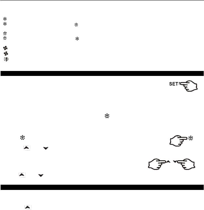
SOLID-STATE THERMOSTAT DESCRIPTIONS
1. FRONT PANELCOMMANDS
To display target set point; in programming mode it selects a parameter or confirm an operation.
To start a manual defrost
To view the last alarm occurrence; in programming mode it browses the parameter codes or increases the display value
 To view the last alarm occurrence; in programming mode it browses the parameter codes or decreases the display value
KEY COMBINATION
To lock & unlock the keyboard
To enter in programming mode
To return to the room temperature display
5
Service and Installation Manual
1.1 Function of LEDS
LED |
MODE |
FUNCTION |
|
|
ON |
Compressor enabled |
|
|
|
|
|
|
Flashing |
-Programming Phase (flashing with |
) |
|
|
- Anti-short cycle delay enabled |
|
|
ON |
Defrost enabled |
|
|
|
|
|
|
Flashing |
- Programming Phase (flashing with |
) |
|
|
- Drip time in progress |
|
|
ON |
Fans enabled |
|
|
|
|
|
|
Flashing |
Fans delay after defrost in progress. |
|
|
|
|
|
|
ON |
An temperature alarm happened |
|
|
|
|
|
2. MAIN FUNCTIONS
2.1 HOW TO SEE THE SETPOINT
1.Push and immediately release the SET key: the display will show the set point value.
2.Push and immediately release the SET key or wait for 5 seconds to display the sensor value again.
2.2 HOW TO CHANGE THE SETPOINT
1. Hold the SET key for more than 2 seconds to change the set point value.
2. The value of the set point will be displayed and the LED starts blinking.
3.To change the set value, push the  or
or  key within 10s.
4.To set new point value, push the SET key again or wait 10s.
2.3 HOW TO START A MANUAL DEFFROST
Hold the |
key for more than 2 seconds and a manual defrost will start |
|
2.4 HOW TO LOCK THE KEYBOARD |
||
1. Hold the |
and |
keys for more than 3s. |
2.The “POF”message will be displayed and the keyboard will be locked. At this point, it will be possible only to see the set point or the MAX or Min temperature stored.
3.If a key is pressed more than 3s the ”POF”message will be displayed.
2.5 HOW TO UNLOCK THE KEYBOARD
Hold the |
and |
keys together for more than 3s until the “POF”message is displayed. |
3. ALARM SIGNALS
HOW TO SEE THE ALARM AND RESET THE RECORDED ALARM
1.Push the or  key to display the alarm signals.
2.When the signal is displayed, hold the SET key until the “rst”message is displayed, and push the SET key again. The “rst”message starts blinking and the normal temperature will be displayed.
Message |
Cause |
Outputs |
|
“P1” |
Room probe failure |
Compressor output according to par. |
|
|
|
“Con” and “COF” |
|
“P2” |
Evaporator probe failure |
Defrost end is timed |
|
|
|
|
|
“HA” |
Maximum temperature alarm |
Outputs unchanged. |
|
|
|
|
|
“LA” |
Minimum temperature alarm |
Outputs unchanged. |
|
“dA” |
Door open |
Compressor and fans restarts |
|
“EA” |
External alarm |
Output unchanged. |
|
“CA” |
Serious external alarm (i1F=bAL) |
All outputs OFF. |
|
“CA” |
Pressure switch alarm (i1F=PAL) |
All outputs OFF |
6

Service and InstallationManual
MAINTENANCE
The unit must be turned OFF and disconnected from the power source whenever
performing service, maintenance functions or cleaning the refrigerated area.
DANGER
Refrigerators and Freezers
The interior and exterior can be cleaned using soap and warm water. If this isn't sufficient, try ammonia and water or a nonabrasive liquid cleaner. When cleaning the exterior, always rub with the "grain" of the stainless steel to avoid marring the finish.
Do not use an abrasive cleaner because it will scratch the stainless steel and plastic and can damage the breaker strips and gaskets.
Cleaning the Condenser Coil
The condenser coil requires regular cleaning and it is recommended every 90 days. In some instances, you may find that there is a large amount of debris and dust or grease accumulated prior to the 90 day time frame. In these cases the condenser coil should be cleaned every 30 days.
If the build up on the coil consists of only light dust and debris, the condenser coil can be cleaned with a simple brush. Heavier dust build-up may require a vacuum or even compressed air to blow through the condenser coil.
If heavy grease is present, there are de-greasing agents available for refrigeration use and specifically for the condenser coils. The condenser coil may require cleaning with the de-greasing agent and then blown through with compressed air.
Failure to maintain a clean condenser coil can initially cause high temperatures and excessive run times. Continuous operation with dirty or clogged condenser coils can result in compressor failures. Neglecting the condenser coil cleaning procedures will void any warranties associated with the compressor or cost to replace the compressor.
Never use a high pressure water wash for this cleaning procedure as water can damage the electrical components located near or at the condenser coil.
DANGER
In order to maintain proper refrigeration performance, the condenser fins must be cleaned of dust, dirt and grease regularly. It is recommended that this be done at least every three months. If conditions are such that the condenser is totally blocked in three months, the frequency of cleaning should be increased. Clean the condenser with a vacuum cleaner or stiff brush. If extremely dirty, a commercial-grade condenser cleaner may be required.
Stainless Steel Care and Cleaning
To prevent discoloration of rust on stainless steel several important steps need to be taken. First, we need to understand the properties of stainless steel. Stainless steel contains 70-80% iron which will rust. It also contains 12-30% chromium which forms an invisible passive film over the steels surface which acts as a shield against corrosion. As long as the protective layer is intact, the metal is still stainless. If the film is broken or contaminated, outside elements can begin to breakdown the steel and begin to form rust of discoloration.
Proper cleaning of stainless steel requires soft cloths or plastic scouring pads,
NEVER USE STEEL PADS, WIRE BRUSHES OR SCRAPERS!
DANGER
7
 Loading...